

Page 1

Programmable AC/DC Power Source
ASR-3000 Series
USER MANUAL
ISO-9001 CERTIFIED MANUFACTURER
Page 2

This manual contains proprietary information, which is protected by
copyright. All rights are reserved. No part of this manual may be
photocopied, reproduced or translated to another language without
prior written consent of Good Will company.
The information in this manual was correct at the time of printing.
However, Good Will continues to improve products and reserves the
rights to change specification, equipment, and maintenance
procedures at any time without notice.
Good Will Instrument Co., Ltd.
No. 7-1, Jhongsing Rd., Tucheng Dist., New Taipei City 236, Taiwan.
Page 3

Table of Contents
Table of Contents
SAFETY INSTRUCTIONS .................................................. 5
GETTING STARTED .......................................................... 9
ASR-3000 Series Overview ..................................... 10
Appearance ........................................................... 16
Theory of Operation .............................................. 25
OPERATION .................................................................. 34
Set Up ................................................................... 36
Menu Tree ............................................................. 58
Basic Operation ..................................................... 63
Advanced Settings ............................................... 100
EXTERNAL CONTROL ................................................... 108
Using External Control I/O .................................. 109
Using External Signal Input Function .................. 110
Compiling Arbitrary Waveform Input ................... 113
MISCELLANEOUS ......................................................... 123
T Ipeak, hold ....................................................... 124
IPK CLR ............................................................... 126
Power ON ............................................................ 127
Buzzer ................................................................. 129
Remote Sense ...................................................... 130
Slew Rate Mode ................................................... 132
Output Relay ....................................................... 134
THD Format ........................................................ 135
External Control ................................................... 137
V Unit .................................................................. 138
TEST MODE FUNCTION ............................................... 139
3
Page 4

ASR-3000 Series User Manual
Sequence Mode ................................................... 140
Simulate Mode .................................................... 157
COMMUNICATION INTERFACE .................................... 170
Interface Configuration ........................................ 171
FAQ .............................................................................. 190
APPENDIX .................................................................... 191
Firmware Update ................................................. 191
Factory Default Settings ....................................... 193
Error Messages & Messages ................................ 197
Specifications ...................................................... 204
Information of Name Order ................................. 213
ASR-3000 Dimensions ......................................... 214
Declaration of Conformity ................................... 215
Maintenance & Regular Inspection ...................... 216
INDEX .......................................................................... 218
4
Page 5

SAFETY INSTRUCTIONS
WARNING
Warning: Identifies conditions or practices that
could result in injury or loss of life.
CAUTION
Caution: Identifies conditions or practices that
could result in damage to the ASR-3000 or to other
properties.
DANGER High Voltage
Attention Refer to the Manual
Protective Conductor Terminal
Earth (ground) Terminal
SAFETY INSTRUCTIONS
This chapter contains important safety
instructions that you must follow during
operation and storage. Read the following before
any operation to ensure your safety and to keep
the instrument in the best possible condition.
Safety Symbols
These safety symbols may appear in this manual or on the
instrument.
5
Page 6

ASR-3000 Series User Manual
Do not dispose electronic equipment as unsorted
municipal waste. Please use a separate collection
facility or contact the supplier from which this
instrument was purchased.
General
Guideline
CAUTION
Do not place any heavy object on the ASR-3000.
Avoid severe impact or rough handling that
leads to damaging the ASR-3000.
Do not discharge static electricity to the ASR-
3000.
Use only mating connectors, not bare wires, for
the terminals.
Do not block the cooling fan opening.
Do not disassemble the ASR-3000 unless you are
qualified.
If the equipment is used in a manner not
specified by the manufacturer, the protection
provided by the equipment may be impaired.
Due to the fact that ASR-3000 unit weights greater
than 18kg, please resort to the standard kit GRA442-E for transport or remove the unit by at least
two persons in case of danger occurred.
Safety Guidelines
6
Page 7

SAFETY INSTRUCTIONS
Power Supply
WARNING
AC Input voltage range:
200 ~ 240 Vac
Frequency: 47 ~ 63 Hz
To avoid electrical shock connect the protective
grounding conductor of the AC power cord to
an earth ground.
The power switch that is included in the
instrument is not considered a disconnecting
device.
The permanently connected power input is used
as the disconnecting device and shall remain
readily operable.
a. A switch or circuit-breaker must be included
in the installation
b. It must be suitably located and easily reached
c. It must be marked as the disconnecting
device for the equipment.
d. It shall be located near the equipment
Do not position the equipment so that it is
difficult to operate the disconnecting device.
Ask for professional technician for installation.
It requires 200Vac input condition and the
maximum input current [15A (ASR-3200), 22.5A
(ASR-3300), 30A (ASR-3400)], which conforms
to cord diameter by local regulations.
Breaker, of which the specification is required to
larger than 20A (ASR-3200), 30A (ASR-3300),
40A (ASR-3400) individually, should be in the
near proximity of unit.
7
Page 8

ASR-3000 Series User Manual
Cleaning the ASR3000
Disconnect the circuit-breaker or permanently
connected power input before cleaning.
Use a soft cloth dampened in a solution of mild
detergent and water. Do not spray any liquid.
Do not use chemicals containing harsh material
such as benzene, toluene, xylene, and acetone.
Operation
Environment
Location: Indoor, no direct sunlight, dust free,
almost non-conductive pollution (Note below)
Relative Humidity: 20%~ 80%, no condensation
Altitude: < 2000m
Temperature: 0°C to 40°C
(Pollution Degree) EN 61010-1:2010 specifies the pollution degrees
and their requirements as follows. The ASR-3000 falls under degree 2.
Pollution refers to “addition of foreign matter, solid, liquid, or
gaseous (ionized gases), that may produce a reduction of dielectric
strength or surface resistivity”.
Pollution degree 1: No pollution or only dry, non-conductive
pollution occurs. The pollution has no influence.
Pollution degree 2: Normally only non-conductive pollution
occurs. Occasionally, however, a temporary conductivity caused
by condensation must be expected.
Pollution degree 3: Conductive pollution occurs, or dry, non-
conductive pollution occurs which becomes conductive due to
condensation which is expected. In such conditions, equipment
is normally protected against exposure to direct sunlight,
precipitation, and full wind pressure, but neither temperature
nor humidity is controlled.
Storage
environment
Location: Indoor
Temperature: -10°C to 70°C
Relative Humidity: ≤90%, no condensation
Disposal
Do not dispose this instrument as unsorted
municipal waste. Please use a separate collection
facility or contact the supplier from which this
instrument was purchased. Please make sure
discarded electrical waste is properly recycled to
reduce environmental impact.
8
Page 9

GETTING STARTED
ASR-3000 series
ASR-3000 Series Overview ..................................... 10
Series lineup ...................................................................................... 10
Operating Area ................................................................................. 10
Main Features ................................................................................... 13
Accessories ........................................................................................ 14
Appearance ........................................................... 16
Front Panel ........................................................................................ 16
Rear Panel .......................................................................................... 21
Status Bar Icons ............................................................................... 24
Theory of Operation .............................................. 25
Description of ASR-3000 System ................................................. 25
Glossary ............................................................................................. 26
Alarms ................................................................................................ 29
Considerations .................................................................................. 31
Grounding ......................................................................................... 33
GETTING STARTED
This chapter describes the ASR-3000 power
supply in a nutshell, including its main features
and front / rear panel introduction.
9
Page 10

ASR-3000 Series User Manual
Model Name
Power Rating
Max. Output Current
Max. Output Voltage
ASR-3200
2000 VA
20 / 10 A
400 Vrms / 570 Vdc
ASR-3300
3000 VA
30 / 15 A
400 Vrms / 570 Vdc
ASR-3400
4000 VA
40 / 20 A
400 Vrms / 570 Vdc
ASR-3000 Series Overview
Series lineup
The ASR-3000 series consists of 3 models, the ASR-3200, ASR-3300
and ASR-3400, differing only in capacity. Note that throughout the
user manual, the term “ASR-3000” refers to any of the models,
unless stated otherwise.
Operating Area
10
Page 11

GETTING STARTED
11
Page 12

ASR-3000 Series User Manual
12
Page 13

GETTING STARTED
Performance
Maximum AC output voltage is 400 Vrms
Maximum DC output voltage is 570 Vdc
Maximum output frequency is 999.9 Hz in AC
mode
Supported AC+DC waveform application
DC full capacity output ability
Output voltage total harmonic distortion is less
than 0.5% at all frequency
Crest factor reached 6 times high
Main Features
13
Page 14

ASR-3000 Series User Manual
Features
Include sine, square, triangle, arbitrary and DC
output waveforms
Variable voltage, frequency and current limiter
Harmonic voltage and current analysis ability
Excellent and feature-rich measurement
capacity
Sequence and simulate function
External input amplification
AC line synchronized output
Preset memory function
USB memory support
Remote sense
OCP, OPP and OTP protection function
Interface
Built-in LAN, USB host, USB device, RS232 and
GPIB interface
External control I/O
External signal input
Standard
Accessories
Part number
Description
CD ROM
User manual, programming
manual
82GW1SAFE0M*1
Safety guide
62SR-3K0SC101
Input terminal cover
62SR-3K0SC201
Output terminal cover include
remote sensing
GRA-442-E
Rack mount adapter (EIA)
Accessories
Before using the ASR-3000 power source unit, check the package
contents to make sure all the standard accessories are included.
14
Page 15

GETTING STARTED
GTL-246
USB CABLE (USB 2.0 Type AType B Cable, Approx. 1.2M)
Factory
Installed
Options
Part number
Description
Optional 1
European Output Socket
Optional
Accessories
Part number
De scription
GPW-005
Power Cord SJT 12AWG/3C, 3m
Max Length, 105°C, RNB5-8*3P,
RNB3-4*3P UL/CSA Type
GPW-006
Power Cord H05W-F
1.5mm2/3C, 3m Max Length,
105°C, RNB1-5*3P, RNBL2-4*3P
VDE Type
GPW-007
Power Cord VCT 3.5mm2/3C,
3m Max Length, 105°C, RNB58*3P, RNB3-4*3P PSE Type
GRA-442-J
Rack mount adapter (JIS)
GTL-137
Output power wire
(Load wire_10AWG: 50A, 600V)
(Sense wire_16AWG: 20A, 600V)
GTL-232
RS232C cable, approx. 2M
GTL-248
GPIB Cable, approx. 2M
ASR-002
External Three Phase Control
Unit
APS-008
Air inlet filter
15
Page 16

ASR-3000 Series User Manual
1 2 3 4 5 6 7 8 9 A
B
C
D
E
F
G
HIJKM L
Item Index
Description
1
Power switch button
2
Output Socket
3
USB interface connector (A Type)
4
LCD screen
5
Function keys (blue zone)
6
Display mode select key
7
Menu key
8
Test key
9
Preset key
A
Arrow keys
B
Range key/Output mode key
C
Scroll wheel
Appearance
Front Panel
16
Page 17

GETTING STARTED
D
Output key
E
Shift key
F
Cancel key
G
Enter key
H
Irms/IPK-Limit button
I
Lock/Unlock button
J
F/F-Limit button
K
V/V-Limit button
L
Numerical Keypad with additional “Shift + key”
shortcut functions (green zone)
M
Air inlet
Item
Description
Power Switch
Turn on the mains power
Output Socket
Output voltage socket, which has 2
versions in accordance with different
regions: Universal and European types,
in front panel.
USB A Port
The USB port is used for data transfers
and upgrading software. Also, it is
available for screenshot hardcopy in
association with the Hardcopy key.
Note
It supports FAT32 format with maximum 32G storage
only.
LCD Screen
Displays the setting and measured
values or menu system
17
Page 18

ASR-3000 Series User Manual
Function Keys
Assigned to the functions displayed on
the right side of the screen.
Display Mode
Select Key
Selects between standard, simple and
harmonic analysis mode.
Menu Key
Enters the Main menu or goes back to
one of the display modes.
Test Key
Puts the instrument into the Sequence
and Simulation control mode.
Preset Key
Puts the instrument into Preset mode.
Arrow Keys
The arrow keys are used to select the digit
power of a value that is being edited.
Range Key
Switches between the 100V, 200V and
AUTO ranges
Output Mode
+
Selects between the AC+DC-INT, ACINT, DC-INT, AC+DC-EXT, AC-EXT,
AC+DC-ADD, AC-ADD, AC+DC-Sync and
AC-Sync modes.
Scroll Wheel
Used to navigate menu items or for
increment/decrement values one step at
a time.
Output Key
Turns the output on or off.
18
Page 19

GETTING STARTED
Shift Key
Turns on the shift state, which enables
shortcut operations with an icon
indicated on the top status bar. The shift
state, which allows continuous shortcut
operations, is kept until another press
on shift key again.
Note
When performing shortcut operations, press shift key
followed by another shortcut function key. Do Not
press both shift key and shortcut function key
simultaneously.
Cancel Key
Used to cancel function setting menus
or dialogs.
Enter Key
Confirms selections and settings.
Irms
Used for setting the maximum output
current.
IPK-Limit
+
Used to set the peak output current limit
value.
Lock/Unlock Key
Used to lock or unlock the front panel
keys except output key. Simply press to
lock, whilst long press to unlock.
F Used for setting the output frequency
(DC mode N/A).
F-Limit
+
Used for setting the output frequency
limit value (DC mode N/A).
V Used for setting the output voltage.
19
Page 20
ASR-3000 Series User Manual
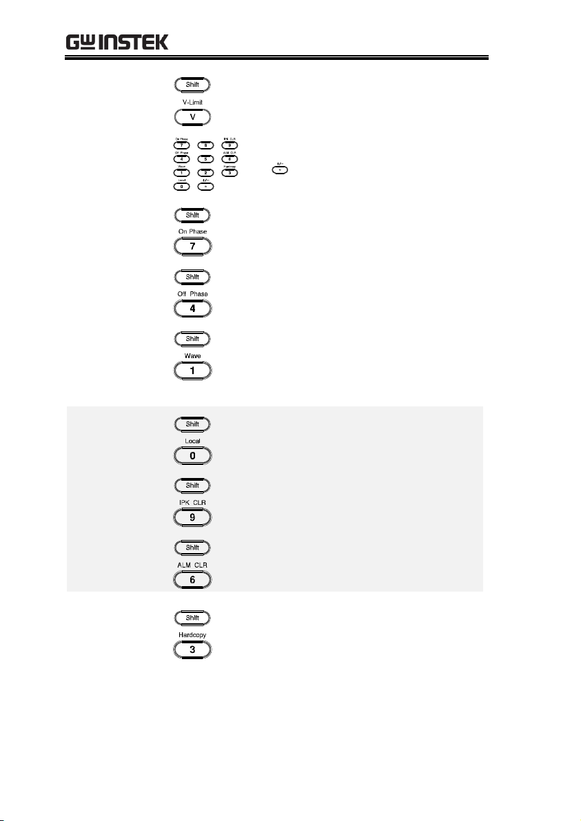
V-Limit
+
Used for setting the output voltage limit
value.
Keypad
Used to input power of a value directly.
The key is used to input decimal /
plus or minus.
On Phase
+
Sets the on phase for the output voltage.
Off Phase
+
Sets the off phase for the output voltage.
Output
Waveform
+
Selects between the Sine, Square,
Triangle and ARB 1~16 waveforms
(not available for DC-INT, AC+DC-EXT
and AC-EXT).
Local Mode
+
Switches operation back to local mode
from remote mode.
IPK CLR
+
Used to clear peak output current value.
ALM CLR
+
Clears alarms.
Hardcopy Key
+
Used to take a screenshot. Make sure an
USB flash disk in well inserted before
the action.
Air Inlet
Air inlet for cooling the inside of the
ASR-3000 series.
20
Page 21

Rear Panel
13 2
4 5 6 7 8 9
Item Index
Description
1
Line input terminal
2
Front panel output socket circuit breaker
3
Output terminal with remote sensing input terminal
4
External I/O connector
5
GPIB connector
6
USB interface connector (B Type)
7
Ethernet (LAN) connector
8
RS232 connector
9
External signal input/
External synchronized signal input
GETTING STARTED
21
Page 22

ASR-3000 Series User Manual
Item
Description
AC Power Input
terminal
AC inlet
(M4 screw type, 8 ~ 22 AWG)
Circuit Breaker
When front panel output socket
output current reaches 15A, the
circuit breaker will be activated
automatically to cut off output. Press
the button to reset the function.
Output Te rminal
with Remote
Sensing Input
terminal
L, N, : Output voltage terminal
(M4 screw type, 8 ~ 22 AWG)
+S, -S: Remote sensing input
terminal is for compensation of
load wire voltage drop.
External Control
I/O Connector
Used to control ASR-3000 externally
by using the logic signal and
monitor Sequence function status.
GPIB Connector
The GPIB connector for
controlling the ASR-3000 remotely.
USB
USB port for controlling the ASR3000 remotely.
Ethernet Port
The Ethernet port is used for
remote control.
RS232C
Connector
The RS232C connector for
controlling the ASR-3000 remotely.
22
Page 23

GETTING STARTED
External Signal
Input Connector
Synchronizing the output frequency
with this external input signal for
SYNC or outputting the amplified
external signal with this external
input signal for EXT and ADD.
23
Page 24

ASR-3000 Series User Manual
Status bar
Status bar
/
Indicates if the output is ON or OFF.
Indicates the output power as a percentage of full
scale.
Indicates if the output range is 100V, 200V or
AUTO.
Indicates if the output waveform is Sine, Square,
Triangle or ARB 1 - 16.
The alarm icon will appear on the status bar
when one of the protection functions is tripped.
Indicates the shift key is pressed which enables
shortcut operations with each key.
Indicates that the ASR-3000 is under remote
mode.
Indicates that the Remote Sense function is active.
Indicates that a USB flash drive is detected in the
front panel host port.
Indicates that the LAN interface is activated.
Indicates that the front panel lock is active.
Status Bar Icons
24
Page 25

GETTING STARTED
Input EMI Filter
and PFC Circuit
A two stage π filter and a passive PFC circuit
that convert AC power to DC power.
Auxiliary Power
It converts AC power line input to +24Vdc
power for the PWM ICs, fan, among other
devices.
Isolation DC to
DC Converter
The isolation DC to DC converter is able to
convert high DC level to lower that not only
offers inverter a stable DC source but separates
primary and secondary side efficiently.
Output Power
Stage (inverter)
Two inverter power stages are in parallel or in
series that provide, in addition to AC and DC
output, sinusoid, square as well as triangle
output waveforms.
Digital
Processor and
Close Loop
Control Circuit
Composition of the C2000 DSP device and the
closed-loop control circuit that execute inverter
action, output measurement and all of the
relevant protection functions.
Communication
Interface and
Data
Transmission
DSP, FPGA and LCD controller that are
collectively responsible for interface
communication, data transmission, LED panel
control as well as remote control.
Keypad and
Display
CPLD that controls keys action and
communicates with DSP for data transmission.
Theory of Operation
The theory of operation chapter describes the basic principles of
operation, protection modes and important considerations that
must be taken into account before use.
Description of ASR-3000 System
System block are composed of the parts described below.
25
Page 26

Glossary
Rate Output
Maximum
Power Capacity
The maximum value of the output power
capacity will be provided consecutively when
the following situations exist:
Output voltage is 100 to 200 V within the 100 V
range.
Output voltage is 200 to 400 V within the 200 V
range.
Output frequency is 40 to 999.9 Hz in AC mode.
Output frequency is 1 to 999.9 Hz in AC+DC
mode.
Output voltage is 100 to 285 V within the 100 V
range in DC mode.
Output voltage is 200 to 570 V within the 200 V
range in DC mode.
Rate Maximum
Current
The maximum value of the output current (rms
value) will be provided consecutively when the
following situations exist:
Output voltage is 100 V within the 100 V range.
Output voltage is 200 V within the 200 V range.
Output frequency is 40 to 999.9 Hz in AC mode.
Output frequency is 1 to 999.9 Hz in AC+DC
mode.
Output voltage is 100 V within the 100 V range
in DC mode.
Output voltage is 200 V within the 200 V range
in DC mode.
Note
The maximum capacity and current in DC mode is
equal to AC+ DC and AC mode.
ASR-3000 Series User Manual
26
Page 27

GETTING STARTED
Equation:
Maximum Peak
Current (AC-INT
mode only)
The maximum value of the output current (peak
value) will be provided consecutively to a
capacitor input-type rectifying load when the
following situations exist:
Output voltage is 100 to 200 V within the 100 V
range.
Output voltage is 200 to 400 V within the 200 V
range.
Output frequency is 40 to 999.9 Hz in AC mode,
and 1 to 999.9 Hz in AC+DC mode.
Note
Rated maximum current (rms value) x 6 is equal
to maximum peak current
Power Factor (PF)
The power factor, which stands for a ratio of the
active power correlated to the apparent power,
indicates degradation level within efficiency
that results from the phase difference between
AC current and AC voltage.
Equation:
27
Page 28

ASR-3000 Series User Manual
Crest Factor (CF)
The crest factor stands for a ratio of the rms
value correlated to the peak value (crest value)
of the waveform.
Equation:
Note
The crest factor is 1.41 of sine wave.
Inrush Current
Capacity
It indicates the current, which is able to be
supplied to a load, exceeds the rating for a short
period and the duration.
Output Power
Ratio
It indicates the output power of a percentage
where the rated maximum output power is
100%.
28
Page 29

GETTING STARTED
Abnormal Output
This alarm is activated and output will be
disabled immediately when output overvoltage
or overcurrent is detected.
Abnormal Power
Source Block
This alarm is activated and output will be
disabled immediately when internal power
source abnormality is detected. Beware that all
operations will be disabled except for the power
shutdown operation if an error occurs.
Abnormal Internal
Control
This alarm is activated and output will be
disabled immediately when internal control
abnormality is detected. Beware that all
operations will be disabled except for the power
shutdown operation if an error occurs.
V-Limit
Voltage limit protection prevents a high voltage
from damaging the DUT. This alarm can be set
by the user.
F-Limit
Frequency limit protection prevents a high
frequency from damaging the DUT. This alarm
can be set by the user.
OCP
Over current protection prevents high current
from damaging the DUT. This alarm can be set
by the user.
OTP
Over temperature protection for power stage
board. OTP is a hardware protection function.
Only when the unit has cooled can the over
temperature protection alarms be cleared.
Alarms
The ASR-3000 series have a number of protection features. When
one of the protection alarms is tripped, the ALM icon on the
display will be lit and the type of alarm that has been tripped will
be shown on the display. When an alarm has been tripped the
output will be automatically turned off. For details on how to clear
an alarm or to set the protection modes, please see page 197.
29
Page 30

ASR-3000 Series User Manual
OPP
Over Power protection for power stage board. OPP
is a software protection function that is
corresponded with VA value. When the unit has
loaded less then protection point that the alarm be
cleared.
Remote Sense
Error
Sense alarm. This alarm will detect if the sense
wires have been connected to the wrong
polarity.
Power Input
Anomaly
AC input failure. This alarm function is
activated when a low AC input is detected.
FAN Fail
Fan failure. This alarm function is activated
when the fan RPMs drop to an abnormally low
level.
PFC Error
This alarm function is activated when
insufficient output voltage and over
temperature occur in PFC power stage. This
alarm can be set by user.
DCDC Error
This alarm function is activated when over
output voltage or insufficient voltage and over
current occur in DCDC power stage. Contact
local dealer or GW Instek directly for repair.
DCAC Error
This alarm function is activated when transient
output current larger than hardware protection
point and over temperature occur in DCAC
power stage. This alarm can be set by user.
30
Page 31

GETTING STARTED
Inrush Current
When the power supply switch is first turned
on, an inrush current is generated. Ensure there
is enough power available for the power supply
when first turned on, especially if a number of
units are turned on at the same time.
Capacitive Load
When the power supply connects to a capacitive
load, e.g., capacitor, the load is being charged
consecutively and the larger the voltage change, the
more the current grow. Also, the overshoot will be
possibly generated within the currents output,
therefore leading to output turned off thanks to
overcurrent protection from the power supply.
It is suggested to lower down the set voltage output
from power supply so that the voltage of capacitive
load decreases per certain unit time. In addition, a
block diode is necessary to keep current from
flowing back to the output terminal of power
supply. Refer to the figure below where a block
diode connects with the capacitive load in series to
efficiently prevent current from flowing back to the
power supply.
L
N
Capacitive Load
Block Diode
ASR-3000
Considerations
The following situations should be taken into consideration when
using the power supply.
31
Page 32

ASR-3000 Series User Manual
Inductive Load
When the power supply connects to an inductive
load, e.g., inductor, which generates a back EMF
(Electromotive Force) when output current is
accidentally turned off, a backflow diode is
necessary for absorbing the back EMF, which may
cause irreversible damage to the power supply.
Refer to the following figure where a backflow
diode connects with the inductive load in parallel
to effectively absorb the possible back EMF.
L
N
Inductive Load
Backflow Diode
ASR-3000
CAUTION
Ensure the connected diode meets the following
specifications between the load, either capacitor or
inductor, and the ASR-3000 series power supplies.
Maximum reverse voltage: 600 V or higher
Maximum forward current:
ASR-3200: 20 A or more for 100V range, and 10
A or more for 200V range
ASR-3300: 30 A or more for 100V range, and 15
A or more for 200V range
ASR-3400: 40 A or more for 100V range, and 20
A or more for 200V range
32
Page 33

GETTING STARTED
Grounded Neutral
Output
Basically, grounded return on the neutral output is
allowed for ASR-3000 series and electric shock may
occur if not following the grounding procedure
based on the local electrical safety codes. In some
cases, 0 V is specifically required between ground
and neutral, which can substantially moderate
ground loops, thus keeping sensitive equipment
from effects of ground loops and reducing ground
noise.
Ground & Neutral
Shortcut
Illustration
CAUTION
Owning to the fact that the neutral has been shortcut
with the ground which is referenced to the chassis
ground, few electric shocks may still take place from
time to time, for which we sincerely ask your
additional attention.
Grounding
The output terminals of the ASR-3000 series are isolated with
respect to the protective grounding terminal. The insulation
capacity of the load, the load cables and other connected devices
must be taken into consideration when connected to the protective
ground or when floating.
33
Page 34

ASR-3000 Series User Manual
Set Up ................................................................... 36
Power Up ........................................................................................... 36
How to Use the Instrument ........................................................... 37
Output Terminals ............................................................................. 40
Using the Rack Mount Kit ............................................................. 44
Edit Arbitrary Waveform ............................................................... 45
Reset to Factory Default Settings .................................................. 49
View Firmware Version and Serial Number ............................... 50
USB Driver Installation .................................................................. 51
Filter Installation .............................................................................. 54
Wire Gauge Considerations ........................................................... 56
Menu Tree ............................................................. 58
Main Page ............................................................................. 59
Function Keys................................................................................... 60
AC+DC-INT, AC+DC-EXT, AC-EXT, AC+DC-
ADD, AC-ADD ................................................................ 60
AC-INT ................................................................................ 60
DC-INT ................................................................................ 61
AC+DC-Sync, AC-Sync .................................................... 61
Menu ..................................................................................... 62
Basic Operation ..................................................... 63
Select the Output Mode .................................................................. 64
Select the Voltage Range................................................................. 66
Select the Output Waveform ......................................................... 67
Setting the Frequency Limit ........................................................... 76
Setting the Output Frequency & Signal ....................................... 79
Setting the Peak Current Limit ...................................................... 81
Setting the Output Current Level ................................................. 83
Setting the Output On Phase ......................................................... 85
Setting the Output Off Phase ........................................................ 87
Switch the Display Modes .............................................................. 89
Using the Measurement Function ................................................. 92
Switch the Measurement Format .................................................. 95
Panel Lock ......................................................................................... 97
Alarm Clear ....................................................................................... 98
Turning the Output On/Off ......................................................... 99
OPERATION
34
Page 35

OPERATION
Advanced Settings ............................................... 100
Using the Remote Sense Function .............................................. 100
Local Sense ........................................................................ 100
Remote Sense .................................................................... 101
Preset Settings ................................................................................. 103
Save Preset Settings to Local Memory .......................... 103
Load Preset Settings to Local Memory ......................... 104
Manage Preset Settings .................................................... 105
35
Page 36

Set Up
Steps
1. Connect the AC power
cords to the AC input
terminals.
Red Line (L)
Black Neutral (N)
Green GND ( )
Line
Neutral
Ground
2. Install the power cord
cover followed by
fastening the two
screws to fix the
cover.
3. The AC power cords
are perfectly
connected with the
AC input terminals.
4. Press the POWER key. The splash screen will
appear momentarily before the continuous
mode screen appears with the settings loaded.
CAUTION
The power supply takes around 20 seconds to fully
turn on and shutdown.
Do not turn the power on and off quickly.
Power Up
ASR-3000 Series User Manual
36
Page 37

OPERATION
Background
The ASR-3000 AC power supplies generally use
the scroll wheel, Arrow keys, Numerical Keypad
and Enter keys to edit numerical values or to
select menu options.
Menu navigation is performed using the menu
keys and function keys on the front panel.
The following section will explain some of these
concepts in detail.
Selecting Menu
Items
1. Turn the scroll wheel to select
parameters in menus and lists. The
selected parameter will be
highlighted in orange. The scroll
wheel is also used to
increment/decrement setting
values.
2. Press the Enter key to edit the
parameter or to enter the selected
menu.
Example
The following is an example of the menu list
that appears when the Menu key is pressed.
Selected parameter
How to Use the Instrument
37
Page 38

ASR-3000 Series User Manual
Using the Arrow
Keys and Scroll
Wheel to Edit
Parameter Values
Use the Arrow keys to select a digit power and
then use the scroll wheel to edit the value by
that power.
1. Use the Arrow keys to move the
cursor to the digit of the desired
value.
2. Turn the scroll wheel to edit the
value by the resolution of the
selected digit.
Cursor
3. Repeat the steps above for all the relevant
digits.
4. Press the Enter key to confirm the
edit.
Note
By default the cursor starts at the lowest digit of value.
Using the
Function Keys
The function keys are quick settings keys, the
function of which depends on the current menu
or operation.
38
Page 39

OPERATION
1. Press the Function key that corresponds to the
setting directly to its left side.
2. The setting or parameter is immediately
executed.
Function keys
Corresponding
quick settings
3. Repeat the steps above for all the relevant
digits.
Using the
Numerical Keypad
to Edit Parameter
Values
Use the Arrow keys to select a digit power and
the Numerical keypad to define a power value.
1. Use the Arrow keys to move the
cursor to the digit of the desired
value.
2. Press the Numerical keys to input
the value by the resolution of the
selected digit.
39
Page 40
ASR-3000 Series User Manual
Cursor
3. Repeat the steps above for all the relevant
digits.
4. Press the Enter key to confirm the
edit.
Note
By default the cursor starts at the lowest digit of value.
Background
The output terminals can be output from either
the front panel or from the rear panel. When
DC-INT mode or R200 range is selected, it is Not
available to output power from the front panel.
Supported Plugs
Multi-region terminal socket
Supported standards
IEC, North America, Japan.
EURO CEE type universal plug
WARNING
Dangerous voltages. Ensure that the power to the
instrument is disabled before handling the power
supply output terminals. Failing to do so may lead to
electric shock.
CAUTION
For the front panel output, the maximum output
voltage is 200 VAC and current is 15 A.
Output Terminals
40
Page 41

OPERATION
Front Panel
Output
Connection
1. The front panel has a multi-region power
socket depending on the socket type.
2. Insert the plug from the DUT into the socket.
EURO CEE socket
IEC North America, Japan
WARNING
Dangerous voltages. Ensure output is off before
unplugging the plug from the front panel socket.
3. Turn the power on. The AC power supply is
now ready to power the DUT.
Rear Panel Output
Connection
The rear panel output is used to supply higher
power DUTs.
1. Disconnect the unit from the mains power
socket and turn the power switch off.
2. Connect the output AC power wires to the AC
output terminals.
Red Line (L)
Black Neutral (N)
Green GND ( )
41
Page 42

ASR-3000 Series User Manual
Line Neutral Ground
3. Install the output AC power wires cover
followed by fastening the two screws to fix the
wires cover.
4. The output AC power wires are perfectly
connected with the AC output terminals.
5. Turn the power on. The AC power supply is
now ready to power the DUT.
42
Page 43

OPERATION
Note
Grounded Neutral Output:
ASR-3000 allows for a grounded return on the neutral
output. It is suit for the medical industry that required
between ground with neutral is 0 V essentially.
And possible to mitigate ground loops that is ideal for
reduce ground noise and isolate sensitive equipment
from the effects of ground loops.
WARNING
Because the neutral has been referenced to the
chassis ground, be careful electric shock by yourself.
43
Page 44
ASR-3000 Series User Manual
Background
The ASR-3000 has the following optional Rack
Mount kits, respectively.
Unit Model
Rack Mount kit part
number
ASR-3200
ASR-3300
ASR-3400
GRA-442-E
GRA-442-J
The GRA-442-E is designed to fit into an EIA
rack of 4U-height, while the GRA-442-J is
designed to fit into a JIS rack of 4U-height.
Please see your distributor for further rack
mount details.
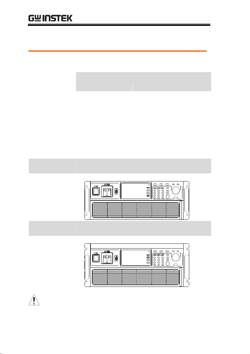
GRA-442-E Series
GRA-439-E Rack
Mount with ASR3000 Diagram
GRA-442-J Series
GRA-439-J Rack
Mount with ASR3000 Diagram
CAUTION
Ensure adequate ventilation is provided when using
the rack mount. Ensure that a gap is given for air
intakes. Failure to do so may cause the instrument to
overheat.
Using the Rack Mount Kit
44
Page 45

OPERATION
Background
The arbitrary waveform editing function is to
select built-in arbitrary waveforms. There are a
number of built-in waveform shapes to choose
from, each of which can be customized with
varied attributes. Finally, choose an ARB NO.
(1~16) to output the selected built-in waveform.
Steps
1. Press the Menu key. The Menu
setting will appear on the display.
2. Use the scroll wheel to go to item 7, Arbitrary Edit
and press Enter to enter the Arbitrary Edit page.
Built-in
Waveform
TRI, STAIR, CLIP, CF-1, CF-2,
SURGE, DST01-22
3. Use the scroll wheel and Enter key to select
waveform along with pertaining attributes and
press Save to confirm settings.
Setting Screen
Overview
Built-in
waveform type
Attributes for the
selected waveform
Visual representation
of the waveform shape
and its attributes
F4 Exit
F1 Save
ARB Waveform
Overview
The following describes each of the built-in
waveforms.
Edit Arbitrary Waveform
45
Page 46

ASR-3000 Series User Manual
TRI The triangle waveform has a settable
number of percentage.
Attributes:
Sym: 0 ~ 100%
ARB NO: 1 ~ 16
STAIR
The staircase waveform has a settable
number of step levels.
Attributes:
Stairs: 1 ~ 100
ARB NO: 1 ~ 16
CLIP
Outputs a clipped sinewave. The
degree to which the sine wave is
clipped is settable.
Attributes:
Ratio: 0.00 ~ 1.00
ARB NO: 1 ~ 16
46
Page 47

OPERATION
CF-1
Crest factor (CF-1) waveform. The crest
factor is settable.
Attributes:
CF: 1.1 ~ 10.0
ARB NO: 1 ~ 16
CF-2
Crest factor (CF-2) waveform. The crest
factor is settable.
Attributes:
CF: 1.5 ~ 2.0
ARB NO: 1 ~ 16
SURGE
The surge waveform has a settable
ACV base level, site size and site
shape.
Attributes:
Type: SQU, SIN (site waveform type)
ACV: 0 ~ 100% (base waveform ampl.)
Site: 0 ~ 100% (site waveform width)
ARB NO: 1 ~ 16
47
Page 48

ASR-3000 Series User Manual
DST01-22
The DST01-22 waveform shape
function simply adds a number Fourier
series terms to create an arbitrary
waveform.
Attributes:
Type: 1 ~ 22 (Number of selectable
ARB waveforms)
ARB NO: 1 ~ 16
Save
4. Press Save[F1] to save the
Arbitrary Edit settings.
Exit
5. Press Exit[F4] to exit from the
Arbitrary Edit settings.
48
Page 49

OPERATION
Background
The default settings can be restored from the
Menu key settings. See page 193 for the default
factory settings.
Steps
1. Press the Menu key. The Menu
settings will appear on the display.
2. Use the scroll wheel to go to item 8, Default
Setting.
3. Press Enter for 2 times to restore the unit back
to the default settings.
Default settings
Reset to Factory Default Settings
49
Page 50

ASR-3000 Series User Manual
Background
The Menu>System Information setting displays
the serial number and firmware version.
Steps
1. Press the Menu key. The Menu
setting will appear on the display.
2. The system information should now be listed
in the item 1, System Information, on the
display
Exit
3. Press Exit[F4] to exit from the
Menu settings.
System Information
Exit [F4]
View Firmware Version and Serial Number
50
Page 51

OPERATION
Background
If the USB Type B interface is to be used for
remote control, the USB driver needs to be
installed.
Note
The USB driver, both gw_asr.inf and gw_asr.cat
can be downloaded from the GW Instek
website.
For information on the USB interface, see page
172.
Steps
1. Connect the rear panel USB -B port on the
ASR-3000 to the PC using a USB Type A to B
cable.
2. Go the Windows Device Manager.
For Windows 7:
Start > Control Panel > Hardware and Sound
> Device Manager
Note
It is available for Windows 7 and Windows 10.
USB Driver Installation
51
Page 52

ASR-3000 Series User Manual
3. The ASR-3000 will be located under Other
Devices in the hardware tree. Right-click the
ASR-3XXX and choose Update Driver Software.
4. From the hardware wizard choose Browse my
computer driver software.
52
Page 53

OPERATION
5. Set the file path to the location of the USB
driver, click Next and finish the driver
installation.
6. ASR-3000 will now be located in the Ports node
of the hardware tree in the Windows Device
Manager if the driver installation was
successful.
53
Page 54

Background
The ASR-3000 has a filter (GW Instek part
number, APS-008) that must first be inserted
under the control panel before operation.
Steps
7. Pull outward as indicated
in the arrow to detach the
snap.
See below
for details
8. Remove th e cover
9. Remove the screws
ASR-3000 Series User Manual
Filter Installation
54
Page 55

OPERATION
10. Move the plastic frame in
the direction indicated by
the arrow
11. Remove the plastic frame.
12. Replace the filter with a
new one.
13. The unit is now ready to power up.
Note
Please clean regularly to avoid damaging the
internal components of the machine
Warning
The following procedure should only be attempted
by competent persons.
Ensure the AC power cord is not connected to
power.
55
Page 56

ASR-3000 Series User Manual
Background
Before connecting the output terminals to a load,
the wire gauge of the cables should be
considered.
It is essential that the current capacity of the
load cables is adequate. The rating of the cables
must equal or exceed the maximum current
rated output of the instrument.
Recommended
Wire Gauge
Wire Gauge
Nominal Cross
Section
Maximum Current
20
0.5 9
18
0.75
11
18
1
13
16
1.5
18
14
2.5
24
12
4
34
10
6
45
8 10
64
6 16
88
4 25
120
2 32
145
1 50
190
00
70
240
000
95
290
0000
120
340
The maximum temperature rise can only be 60
degrees above the ambient temperature. The
ambient temperature must be less than 30 degrees.
Wire Gauge Considerations
56
Page 57

OPERATION
To minimize noise pickup or radiation, the load
wires and remote sense wires should be twistedpairs of the shortest possible length. Shielding of
the sense leads may be necessary in high noise
environments. Where shielding is used, connect
the shield to the chassis via the rear panel
ground screw. Even if noise is not a concern, the
load and remote sense wires should be twistedpairs to reduce coupling, which might impact
the stability of the power supply. The sense
leads should be separated from the power leads.
57
Page 58

Menu Tree
Convention
Use the menu trees as a handy reference for the power
supply functions and properties. The ASR-3200 / ASR3300 / ASR-3400 menu system is arranged in a
hierarchical tree. Each hierarchical level, which is coated
in varied colors, can be navigated through the orders
within the diagrams below.
For example: To set the interface to Buzzer OFF;
○
1 Press the
Menu
key.
○
2 Navigate to the MISC Configuration option.
○
3 Enter the Buzzer option.
○
4 Select OFF.
Menu
System Information
MISC Configuration
T Ipeak, hold
Level 2Level 1 Level 3
IPK CLR
EXEC
Level 4
Power ON Buzzer Remote Sense
ON
OFF
ON
OFF
ON
SEQ
OFF
SIM
1
2 3
4
ASR-3000 Series User Manual
58
Page 59

Main Page
Main Page
MODE
AC+DC-INT
Level 2Level 1 Level 3
ACV
Level 4
DCV FREQ IRMS ON phs WAVE Test
Level 5
FIXED
FREE
SIN
SQU
TRI
ARB 1~16
SEQ
AC-INT
ACV FREQ IRMS WAVE Test
FIXED
FREE
SIN
SQU
TRI
ARB 1~16
SEQ
SIM
DC-INT
DCV I Test
SEQ
AC+DC-EXT
GAIN IRMS
AC-EXT
GAIN IRMS
AC+DC-ADD
ACV DCV FREQ IRMS ON phs
WAVE
FIXED
FREE
SIN SQU
TRI
ARB 1~16
GAIN
AC-ADD
ACV
FREQ IRMS
WAVE
FIXED
FREE
SIN
GAIN
SQU
TRI
ARB 1~16
AC+DC-sync
ACV DCV SIG IRMS
AC-sync
ACV FREQ IRMS
LINE
EXT
LINE
EXT
OFF phs
FIXED
FREE
ON phs OFF phs
FIXED
FREE
OFF phs
FIXED
FREE
ON phs
OFF phs
FIXED
FREE
WAVE
FIXED
FREE
SIN SQU
TRI
ARB 1~16
ON phs
OFF phs
FIXED
FREE
WAVE
FIXED
FREE
SIN SQU
TRI
ARB 1~16
ON phs
OFF phs
FIXED
FREE
SIM
OPERATION
59
Page 60

ASR-3000 Series User Manual
Function Keys
F1
V Vavg Vamx Vmin
P S Q
F2
I Iavg Iamx Imin
IpkH PF CF
F3
P S Q IpkH
PF CF
RUN
HOLD
F4
Function Keys
F1
V Vavg Vamx Vmin
P S Q
F2
I Iavg Iamx Imin
IpkH PF CF
THDv
THDi
F3
P S Q IpkH
PF CF
RUN
HOLD
F4
Function Keys
AC+DC-INT, AC+DC-EXT, AC-EXT, AC+DC-ADD, AC-ADD
AC-INT
60
Page 61

OPERATION
Function Keys
F1
V Vavg Vamx Vmin
P
F2
I Iavg Iamx Imin
IpkH
F3
P IpkH
RUN
HOLD
F4
Function Keys
F1
V Vavg Vamx Vmin
P S Q
F2
I Iavg Iamx Imin
IpkH PF CF
F3
P S Q IpkH
PF CF Freq
RUN
HOLD
F4
DC-INT
AC+DC-Sync, AC-Sync
61
Page 62

Menu
Menu
System Information
MISC Configuration
T Ipeak, hold
Level 2Level 1 Level 3
IPK CLR
EXEC
Level 4
Power ON Buzzer Remote Sense
Slew Rate Mode
ON
OFF
Time
Slope
ON
OFF
ON
SEQ
Output Relay
Enable
Disable
THD Format
IEC
CSA
LAN
DHCP IP Address Subnet Mask Gateway DNS Socket Port
ON
OFF
USB Device
Speed
Full
RS232C
Baudrate Databits Parity Stopbits
9600
(default)
8bits
(default)
None
(default)
1bits
(default)
GPIB
Address
10 (default)
Arbitrary Edit
TRI STAIR CLIP
Default Setting
Special Function
Save / Recall Files
Type Action Memory No.
PRESET
MEM→USB
0~9 or 1~16
SEQUENCE
SIMULATE
ARB
MEM←USB
Delete
TEST
SEQUENCE
SIMULATE
OFF
SIM
External Control
ON
OFF
V Unit(TRI, ARB)
rms
p-p
All Data
Save
Recall
CF-1 / CF-2 SURGE DST01-22
ASR-3000 Series User Manual
62
Page 63

OPERATION
Basic Operation
This section describes the basic operations required to operate the
power supply.
Select the Output Mode → from page 64
Select the Voltage Range → from page 66
Select the Output Waveform → from page 67
Setting the Output Voltage Limit → from page 70
Setting the Output AC/DC Voltage & Gain → from page 73
Setting the Frequency Limit → from page 76
Setting the Output Frequency & Signal → from page 79
Setting the Peak Current Limit → from page 81
Setting the Output Current Level → from page 83
Setting the Output On Phase → page 85
Setting the Output Off Phase → page 87
Switch the Display Modes → from page 89
Using the Measurement Function → from page 92
Switch the Measurement Format → from page 95
Panel Lock → from page 97
Alarm Clear → from page 98
Turning the Output On/Off → from page 99
Before operating the power supply, please see the Getting Started
chapter, page 9.
63
Page 64

ASR-3000 Series User Manual
Background
The ASR-3000 has up to 9 modes to output,
which empower user to have multiple
applications for different scenarios.
Steps
1. Press Shift + Range to access the
MODE selection menu.
+
Alternatively, it is available to use
scroll wheel followed by the Enter
key to enter the MODE menu.
Select the Output Mode
64
Page 65

OPERATION
2. Choose an output mode with scroll wheel.
Mode
Description
AC+DC-INT
AC & DC Internal Output
AC-INT
AC Internal Output
DC-INT
DC Internal Output
AC+DC-EXT
AC & DC External Output
AC-EXT
AC External Output
AC+DC-ADD
AC & DC Additional Output
AC-ADD
AC Additional Output
AC+DC-Sync
AC & DC Synchronal Output
AC-Sync
AC Synchronal Output
INT
The signal source is from
internal. Set the output voltage,
waveform, frequency, on phase
and off phase through the control
panel or the remote control.
EXT
The signal source is from
external. Amplifies and outputs
the external input signal. Set the
voltage gain through the control
panel or the remote control.
ADD
The signals are the total of the
external and internal signal
source. Set the voltage gain for
the external input signal, the
output voltage for the internal
signal source, the output
waveform, frequency, on phase
and off phase through the control
panel or the remote control.
65
Page 66

ASR-3000 Series User Manual
Sync
The signal source is from
internal. The output frequency is
synchronized with the external
TTL input signal or the power
line. This frequency setting can't
be set through the control panel
or the remote control. All of
setting conditions except for
output frequency are as same as
INT mode.
3. Press Enter to confirm the mode selection.
Example
Mode
menu
Background
The Range setting determines the general outlet
voltage range. The ranges available correspond
to common mains output voltage standards.
Steps
1. Press Range to access the Range
menu.
2. Set the voltage range with the F1 ~ F4 soft-keys.
Soft-keys
F1: AUTO
F3: 200V
F4: 100V
3. Press Enter to confirm the Range setting.
Select the Voltage Range
66
Page 67

OPERATION
Example
Range setting
F1
F3
F4
Note
The output voltage values set by user can be divided
into 2 manual settings, both of which have close
relation with voltage range that contains high range
(200V, AUTO) and low range (100V). For instance,
when setting 5 Vrms under 200V range and 3 Vrms
under 100V range, the Vrms setting will change from 5
Vrms to 3 Vrms directly after switching the voltage
range from 200V to 100V.
Also, if the voltage range is changed when the output is
on, the output will be automatically turned off.
Background
The ASR-3000 is capable of outputting sine,
square, triangle and ARB wave shapes while
connecting with external signals.
Steps
1. Press Shift + 1 to access the Wave
menu.
+
Alternatively, it is available to use
scroll wheel followed by the Enter
key to enter the Wave menu.
Select the Output Waveform
67
Page 68

ASR-3000 Series User Manual
2. Choose a waveform with scroll wheel.
Mode
Description
SIN
Sine wave
SQU
Square wave
TRI
Triangle wave
ARB 1 ~ 16
Arbitrary wave 1 ~ 16
68
Page 69

OPERATION
3. Press Enter to confirm the waveform setting.
Wave
setting
Note
Waveform selection is Not available under DC-INT,
AC+DC-EXT and AC-EXT output modes.
For more details about Arbitrary waveforms, refer
to the page 112.
When changing to a waveform with setting higher
than the upper limit of other waveform, the setting
of other waveform will be adjusted to zero forcibly.
For instance, when it is originally SIN output with
ACV in 150 Vrms (200 Vrms for V-Limit), the ACV
will be changed to 0 Vrms (164.5 Vrms for V-Limit)
after output waveform adjusts to TRI.
69
Page 70

ASR-3000 Series User Manual
Background
Setting the voltage limit allows the output
voltage to be set to any level within the voltage
limit range.
Steps
1. Press Shift + V to access the Volt
Limit menu.
+
2.
When it is under AC+DC-INT, DC-INT,
AC+DC-ADD or AC+DC-Sync mode.
Use the scroll wheel to toggle between VPK+
(upper) and VPK- (lower) settings followed by
pressing Enter to get into the parameter.
Proceed to the step 3 for setup.
VPK+
Setting
VPKSetting
Setting the Output Voltage Limit
70
Page 71

OPERATION
When it is under AC-INT, AC-ADD or AC-Sync
mode.
Use the scroll wheel or the numerical keypad to set
value of Vrms limit directly or use the F3 (MAX)
and F4 (MIN) soft-keys to set the limit to the
maximum or minimum value.
AC–INT, AC-ADD, AC-Sync
Vrms
Range
10% ~ 100% full range
voltage
Soft-keys
MAX, MIN
Vrms
Setting
Note
The Vrms Limit value defined by user will be generally
applied to AC-INT, AC-ADD and AC-Sync modes under
the same voltage range, which divides into 2 levels,
high range including AUTO and 200V and low range
covering 100V.
3. Set the voltage limit (VPK+ & VPK-) with the scroll
wheel or the numerical keypad or with the F3
(MAX) and F4 (MIN) soft-keys to set the limit to
the maximum and minimum values, respectively.
AC+DC-INT, DC-INT,
AC+DC-ADD, AC+DC-Sync
VPK+
Range
3.5% ~ 100% full range peak
voltage
Soft-keys
MAX, MIN
VPK-
Range
3.5% ~ 100% full range peak
voltage
71
Page 72

ASR-3000 Series User Manual
Soft-keys
MAX, MIN
VPK+
Setting
VPKSetting
Note
Both the VPK+ and VPK- Limit values defined by user
will be generally applied to AC+DC-INT, DC-INT,
AC+DC-ADD and AC+DC-Sync modes under the same
voltage range, which divides into 2 levels, high range
including AUTO and 200V and low range covering
100V.
4. Press Enter to confirm the voltage limit setting.
Note
Voltage limit setting is Not available for both
AC+DC-EXT and AC-EXT output modes.
There 6 sets of voltage limits in total.
The minimum voltage limit has relative
connection with the voltage setting. That is, the
voltage setting is never beyond the voltage limit.
The range of voltage limit will be limited within
the certain minimum value in accordance with the
output voltage setting.
72
Page 73

OPERATION
Background
The ACV, DCV and Gain settings set the output
voltage level. Before setting the power supply
voltage level, set the voltage range and voltage
limit beforehand.
Steps
1. Press the V key. The ACV
parameter will be selectable.
Also, it is available to use the scroll
wheel followed by the Enter key to
make the ACV parameter
selectable as well.
DCV
When it is under AC+DC-INT, AC+DC-ADD or
AC+DC-Sync mode.
Further use the scroll wheel to navigate to the
DCV parameter and press
Enter
to make DCV
parameter selectable.
When it is under DC-INT mode.
Directly press the V key or use the scroll wheel
to navigate to the DCV parameter and press
Enter
to make DCV parameter selectable.
GAIN
When it is under AC+DC-EXT or AC-EXT mode.
Directly press the V key or use the scroll wheel
to navigate to the GAIN parameter and press
Enter
to make GAIN parameter selectable.
When it is under AC-ADD mode.
Setting the Output AC/DC Voltage & Gain
73
Page 74

ASR-3000 Series User Manual
Further use the scroll wheel to navigate to the
GAIN parameter and press
Enter
to make GAIN
parameter selectable.
2. Set ACV/DCV/GAIN value with the scroll
wheel or with the F1 ~ F4 soft-keys.
AC+DC-INT, AC-INT, DC-INT
ACV
DCV
Range
0 volts ~ full range
Soft-keys
DEF1, DEF2, MAX, MIN
AC+DC-EXT, AC-EXT
GAIN
Range
0 times ~ full range
Soft-keys
DEF1, DEF2, MAX, MIN
AC+DC-ADD, AC-ADD
ACV
DCV
Range
0 volts ~ full range
Soft-keys
DEF1, DEF2, MAX, MIN
GAIN
Range
0 times ~ full range
Soft-keys
DEF1, DEF2, MAX, MIN
AC+DC-Sync, AC-Sync
ACV
DCV
Range
0 volts ~ full range
Soft-keys
DEF1, DEF2, MAX, MIN
3. Press Enter to confirm voltage or gain setting.
Defined Settings
The DEF1 and DEF2 settings are user-defined
settings. By default they are set to 0.0 and 100.0
volts (100V range), 200.0 volts (200V and AUTO
range), respectively and 100 and 200 times for
gain. The MAX and MIN soft-keys set voltage or
gain parameters to the maximum or minimum
value, respectively.
4. Repeat the previous steps 1 ~ 2 to set AC/DC
voltage and gain value with the scroll wheel.
74
Page 75

OPERATION
5. Press and hold either the DEF1 or DEF2 soft-
key until “Saved to DEF1/2” is displayed,
which indicates the voltage and gain settings
are saved to the DEF1 or DEF2 soft-key
individually.
Note
Trying to set the voltage outside of the voltage
limit/range will result in a voltage setting error
being displayed on the screen.
ACV, DCV and GAIN settings under each output
mode and range have their own DEF1 and DEF2
saved values, respectively.
Example of ACV
Setting in the
AC+DC-INT
ACV setting
Defined setting
F3
F4
F1
F2
Example of DCV
Setting in the
DC-INT
DCV setting
Defined setting
F3
F4
F1
F2
Example of GAIN
Setting in the
AC+DC-EXT
GAIN setting
Defined setting
F3
F4
F1
F2
75
Page 76

ASR-3000 Series User Manual
Note
1. Vrms can only be set up to 164.5 Vrms / 329.0 Vrms
for triangular waveform.
2. Go to Menu -> MISC -> V Unit to select the voltage
set value unit.
Background
Setting the frequency limit allows the frequency
output to be set to any level within the limit
range.
Steps
1. Press Shift + F to access the Freq
Limit menu.
+
2. Use the scroll wheel to toggle between Freq Hi
(upper) and Freq Lo (lower) settings followed
by pressing Enter to get into the parameter.
Freq Hi
Setting
Freq Lo
Setting
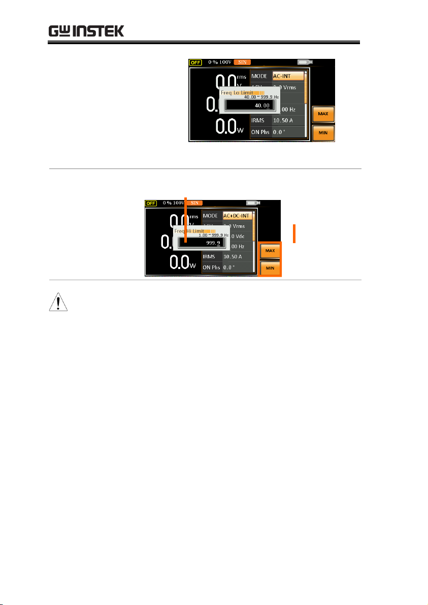
3. Set the frequency limit with the scroll wheel or
with the F3 ~ F4 soft-keys. The MAX and MIN
soft-keys set the frequency limit to the
maximum and minimum, respectively.
Setting the Frequency Limit
76
Page 77

OPERATION
AC+DC-INT, AC+DC-ADD
Freq Hi
Limit
Range
1.00 ~ 999.9 Hz
Soft-keys
MAX, MIN
Freq Lo
Limit
Range
1.00 ~ 999.9 Hz
Soft-keys
MAX, MIN
Freq Hi
Setting
Freq Lo
Setting
AC-INT, AC-ADD
Freq Hi
Limit
Range
40.00 ~ 999.9 Hz
Soft-keys
MAX, MIN
Freq Lo
Limit
Range
40.00 ~ 999.9 Hz
Soft-keys
MAX, MIN
Freq Hi
Setting
77
Page 78
ASR-3000 Series User Manual
Freq Lo
Setting
4. Press Enter to confirm the limit setting.
Example of Freq
Hi Limit Setting
in AC+DC-INT
Freq Limit setting
Min/Max
settings
F3
F4
Note
Frequency limit setting is Not available under DC-
INT, AC+DC-EXT, AC-EXT, AC+DC-Sync and ACSync output modes.
Before change freq limit setting, if FREQ setting
value is bigger than desire freq limit value, the freq
limit value cannot be change accordingly.
The range of frequency limit will be limited within
the certain minimum value in accordance with the
output frequency setting.
There are 2 sets of frequency limits in total.
78
Page 79

OPERATION
Background
The FREQ and SIN settings set the frequency of
the output. Before setting the frequency, set the
frequency limit.
Steps
1. Press the F key to access the FREQ
or SIG parameter depending on
varied modes.
Also, it is available to use the scroll
wheel followed by the Enter key to
make the FREQ or SIG parameter
selectable as well.
2. Set the frequency or signal with the scroll wheel
or with the F1 ~ F4 soft-keys.
AC+DC-INT, AC+DC-ADD
FREQ
Range
1.00 ~ 999.9 Hz
Soft-keys
DEF1, DEF2, MAX, MIN
AC-INT, AC-ADD
FREQ
Range
40.00 ~ 999.9 Hz
Soft-keys
DEF1, DEF2, MAX, MIN
AC+DC-Sync, AC-Sync
SIG
Option
LINE, EXT
3. Press Enter key to confirm the frequency or
signal setting.
Setting the Output Frequency & Signal
79
Page 80

ASR-3000 Series User Manual
Defined Settings
The DEF1 and DEF2 settings are user defined
settings. By default they are set to 50.00 Hz and
60.00 Hz, respectively. The MAX and MIN softkeys set the frequency to the maximum and
minimum, respectively.
4. Repeat the previous steps 1 ~ 2 to set frequency
with the scroll wheel.
5. Press and hold the DEF1 or DEF2 soft-key until
“Saved to DEF1/2” is displayed. This will save
the frequency setting to the DEF1 or DEF2 softkey individually.
Example of
Frequency Setting
in AC+DC-INT
Frequency setting Defined setting
F3
F4
F1
F2
Example of Signal
Setting in the
AC+DC-EXT
Signal setting
Note
Trying to set the frequency outside of the frequency
limit will result in a frequency setting error being
displayed on the screen.
FREQ setting under each output mode has its own
DEF1 and DEF2 saved values, respectively.
80
Page 81

OPERATION
Background
Setting the peak current limit sets a limit on the
current that can be sourced by the power supply.
Once the output current over the setting, the
output will set to off.
Note
When the peak current limit is tripped, an alarm will
sound. Press
Shift + Cancel
to clear the Ipk alarm.
Steps
1. Press Shift + Irms to access the IPK
Limit menu.
+
2. Use the scroll wheel to toggle between IPK+
(upper) and IPK- (lower) settings followed by
pressing Enter to get into parameter, respectively.
IPK+
IPK-
Setting the Peak Current Limit
81
Page 82

ASR-3000 Series User Manual
3. Set the peak current (IPK+ & IPK-) with the
scroll wheel or with the F3 (MAX) and F4 (MIN)
soft-keys to set the current limit to the maximum
and minimum values, respectively.
AC+DC-INT, AC–INT, DC-INT, AC+DC-EXT,
AC–EXT, AC+DC-ADD, AC–ADD, AC+DC-
Sync, AC-Sync
IPK+
Range
50 ~ 105% of rate peak
current
Soft-keys
IPK Limit On/Off, MAX,
MIN
IPK-
Range
-105 ~ -50% of rate peak
current
Soft-keys
IPK Limit On/Off, MAX,
MIN
Example of IPK+
Limit Setting in
the AC+DC-INT
IPK+ Limit setting Soft-keys setting
F3
F4
F1
Example of IPKLimit Setting in
the AC+DC-INT
IPK- Limit setting Soft-keys setting
F3
F4
F1
82
Page 83

OPERATION
IPK Limit
On/Off
In theory, It is the function which keeps the IPK
limits (+ & -) within the certain range when the
predefined values are reached. If, however, this
function is turned off, the output will be disabled
instantly when either IPK+ or IPK- limit is
reached.
4. Press Enter to confirm the peak current setting.
Note
IPK Limit is set ON by default.
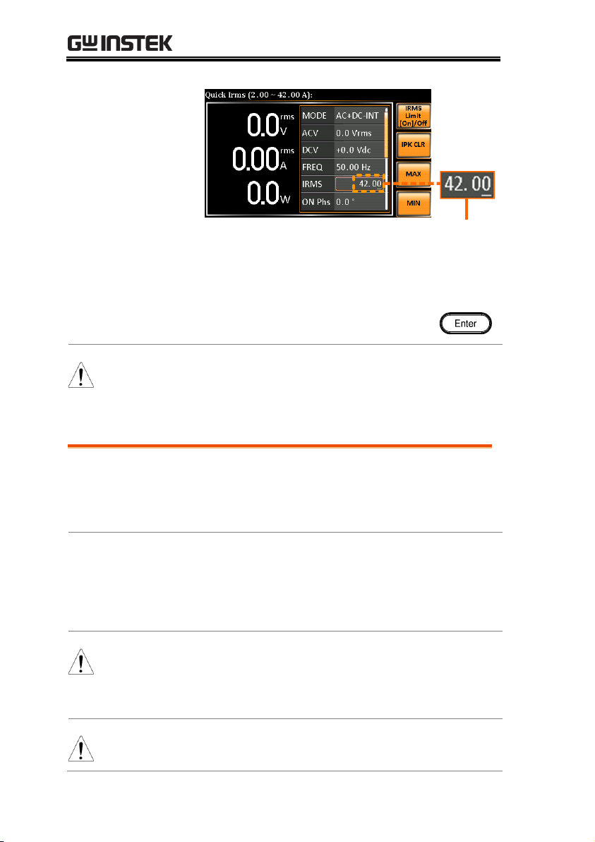
Background
The IRMS and I settings set the current of the
output. Setting the RMS or AVG current sets a
limit on the current that can be sourced by the
power supply. Once the output current is over
the setting, the output will set to off.
Steps
1. Press Irms to access the IRMS or I
menu depending on varied modes.
Also, it is available to use the scroll
wheel followed by the Enter key to
make the IRMS or I parameter
selectable as well.
2. Set the IRMS/I level with the scroll wheel or
with the F3 ~ F4 soft-keys. The MAX and MIN
soft-keys set the IRMS or I level to the
maximum and minimum, respectively.
AC+DC-INT, AC–INT, DC-INT, AC+DC-EXT,
AC–EXT, AC+DC-ADD, AC–ADD, AC+DC-
Sync, AC-Sync
IRMS/I
Range
5% ~ 105% of rate current
Setting the Output Current Level
83
Page 84

ASR-3000 Series User Manual
Soft-keys
IRMS Limit On/Off, IPK
CLR, MAX, MIN
Example of IRMS
Setting in the
AC+DC-INT
IRMS setting
Soft-keys setting
F3
F4
F1
F2
Example of I
Setting in the
DC-INT
I setting
Soft-keys setting
F3
F4
F1
F2
IRMS & I Limit
On/Off
Almost identical with the concept of previous IPK
Limit function, the IRMS/I Limit function keeps the
IRMS/I value within the certain limit when the
predefined value is reached. If, on the other hand,
this function is turned off, the output will be
disabled instantly when IRMS/I Limit off level is
reached.
Note
IRMS Limit is set ON by default. The IRMS minimum
value will not be less than 1A.
84
Page 85

OPERATION
Background
The on phase setting sets the starting phase of
the voltage output.
Steps
1. Press Shift + 7 to make the ON Phs
parameter selectable.
+
Also, it is available to use the scroll
wheel followed by the Enter key to
make the ON Phs parameter
selectable as well.
2. Set the ON Phs setting with the scroll wheel or
the numerical keypad or with the F3 (MAX) and
F4 (MIN) soft-keys to set the On Phase to the
maximum and minimum values, respectively.
AC+DC-INT, AC-INT, AC+DC-ADD,
AC-ADD, AC+DC-Sync, AC-Sync
ON Phs
Range
0.0° ~ 359.9°
Soft-keys
FIXED/FREE, MAX, MIN
3. Press Enter to confirm the On Phase setting.
Setting the Output On Phase
85
Page 86

ASR-3000 Series User Manual
Example of On
Phase Setting
On Phase setting
F1
F3
F4
Soft-keys setting
FIXED & FREE
Modes
Pressing the F1 key to toggle between modes of
FIXED, which indicates the user-defined on-phase
degree, or FREE, which represents the degree of
on-phase is freely determined by the unit itself.
When FREE is selected, the both F3-MAX and F4MIN keys are grayed out, signaling the
unavailability by user.
Example of On
Phase Setting in
FREE Mode
On Phase setting
FREE
selected
86
Page 87

OPERATION
Background
The off phase setting sets the ending phase of the
voltage output.
Steps
1. Press Shift + 4 to make the OFF Phs
parameter selectable.
+
2. Also, it is available to use the
scroll wheel followed by the Enter
key to make the OFF Phs
parameter selectable as well.
3. Set the OFF Phs setting with the scroll wheel or
with the F3 (MAX) and F4 (MIN) soft-keys to set
the Off Phase to the maximum and minimum
values, respectively.
AC+DC-INT, AC-INT, AC+DC-ADD,
AC-ADD, AC+DC-Sync, AC-Sync
OFF Phs
Range
0.0° ~ 359.9°
Soft-keys
FIXED/FREE, MAX, MIN
4. Press Enter to confirm the Off Phase setting.
Example of OFF
Phase Setting
OFF Phase setting
F1
F3
F4
Soft-keys setting
Setting the Output Off Phase
87
Page 88

ASR-3000 Series User Manual
FIXED & FREE
Modes
Pressing the F1 key to toggle between modes of
FIXED, which indicates the user-defined off-phase
degree, or FREE, which represents the degree of
off-phase is freely determined by the unit itself.
When FREE is selected, the both F3-MAX and F4MIN keys are grayed out, signaling the
unavailability by user.
Example of OFF
Phase Setting in
FREE Mode
OFF Phase setting
FREE
selected
88
Page 89
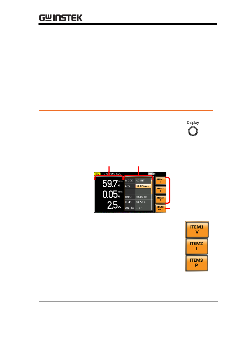
OPERATION
Steps
1. Press the Display key.
2. The display mode will toggle each
time when the key is pressed
besides locked mode.
Standard Mode
Measurement Setting
Configurable
measurements
Hold
measurement
Configuring the
Standard Mode
Measurements
1. Press the F1(ITEM1), F2(ITEM2) or
F3(ITEM3) soft-key to enter each
menu.
2. Use the scroll wheel to select a measurement
item and press Enter to confirm. Refer to page 92
for more details of measurement parameters.
Switch the Display Modes
The ASR-3000 power supply has three display modes. The
standard display mode shows the power supply setup in the
middle and the 3 configurable measurements on the right that
correspond to the far-left live-time measurements section. The
simple display mode shows all measurement items available on the
ASR-3000 with 3 measurement formats switchable at any time. The
harmonic display mode shows both harmonic voltage and
harmonic current relevant measurements for user.
89
Page 90
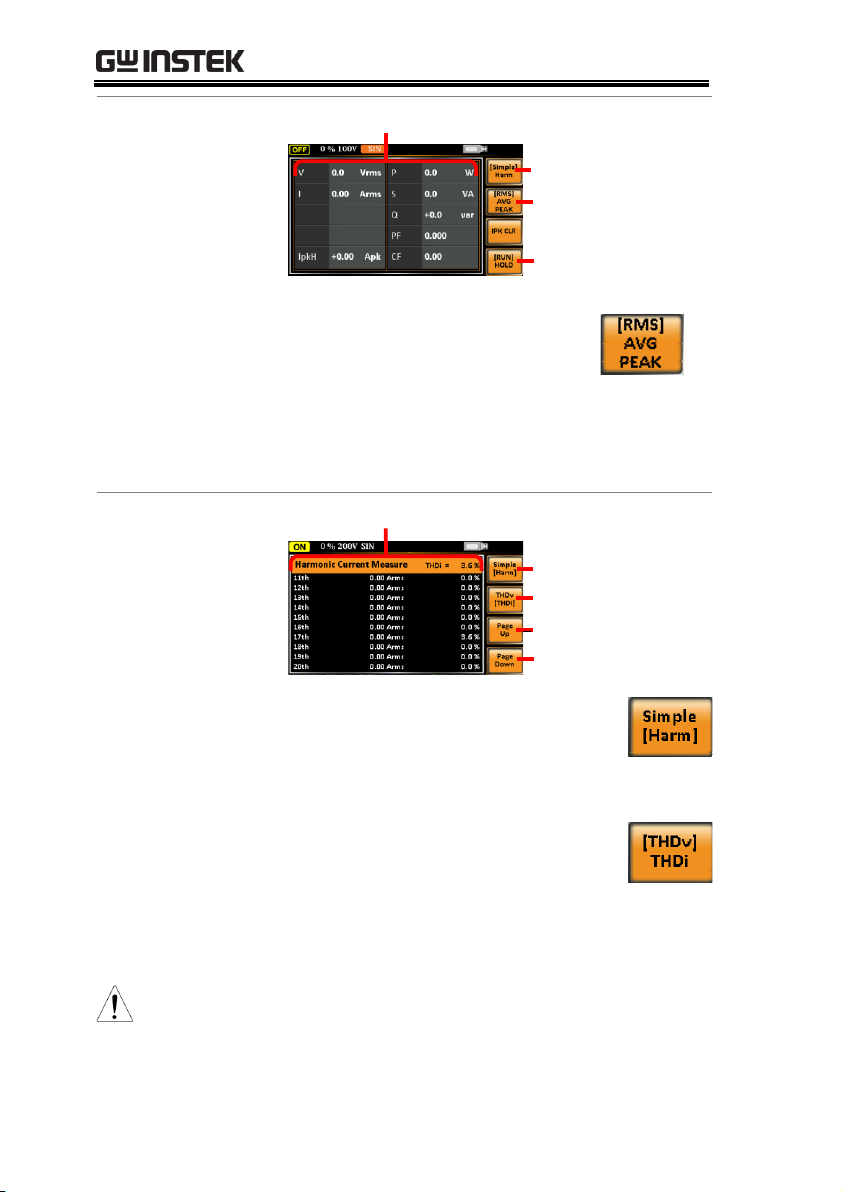
ASR-3000 Series User Manual
Simple Mode
Measurement Items
Hold
measurement
Measuremt
formts
Simple/Harm
Configuring the
Simple Mode
Measurements
1. Press the F2 (RMS/AVG/PEAK)
soft-key to toggle among each
mode of format.
2. The display will show parameters of
measurement for each format. Refer to the page
95 for details.
Harmonic Mode
Measurement Items
Page Down
Page Up
THDv/THDi
Simple/Harm
Configuring the
Harmonic Mode
Measurements
1. First switch to the Simple mode
followed by pressing the F1
(Simple/Harm) soft-key to enter
the Harm display mode.
2. Pressing the F2 (THDv/THDi)
soft-key to toggle between Total
Harmonic Distortion Volt (THDv)
and Total Harmonic Distortion
Current (THDi) measurements.
Note
Harmonic mode is available for AC-INT mode and
50/60Hz output frequency. SIN, SQU, TRI and ARB 1 16 waveforms are also available.
90
Page 91

OPERATION
3. When the measurements are
beyond one page, which consists of
up to 10 items, press the F3 (Page
Up) and F4 (Page Down) soft-keys
to flip through pages.
Hold
Measurement
Press the soft-key F4 to toggle hold on
or off. This function will “hold” the
current measurements on the display,
which means the measurements won’t
be updated until the function is
released.
Note
Hold measurement is available for the Standard and
Simple display modes only.
91
Page 92

ASR-3000 Series User Manual
Steps
1. Press the Display key to switch to
the Standard display mode.
2. Press the F1(ITEM1), F2(ITEM2) or
F3(ITEM3) soft-key to enter each
menu.
3. Use the scroll wheel to select a measurement
item and press Enter to confirm.
ITEM 1
V Root Mean Square Voltage
Vavg
Average Voltage
Vmax
Maximum Peak Value of Output
Voltage
Vmin
Minimum Peak Value of Output
Voltage
P Real Power
S Apparent Power
(n/a in DC-INT mode)
Q Reactive Power
(n/a in DC-INT mode)
Using the Measurement Function
The 3 configurable measurements, which indicate the live-time
measurement in varied units, on the far-right side within the
standard display mode can be switched by user anytime in the
process of power output, thus providing an instantaneous analysis.
92
Page 93
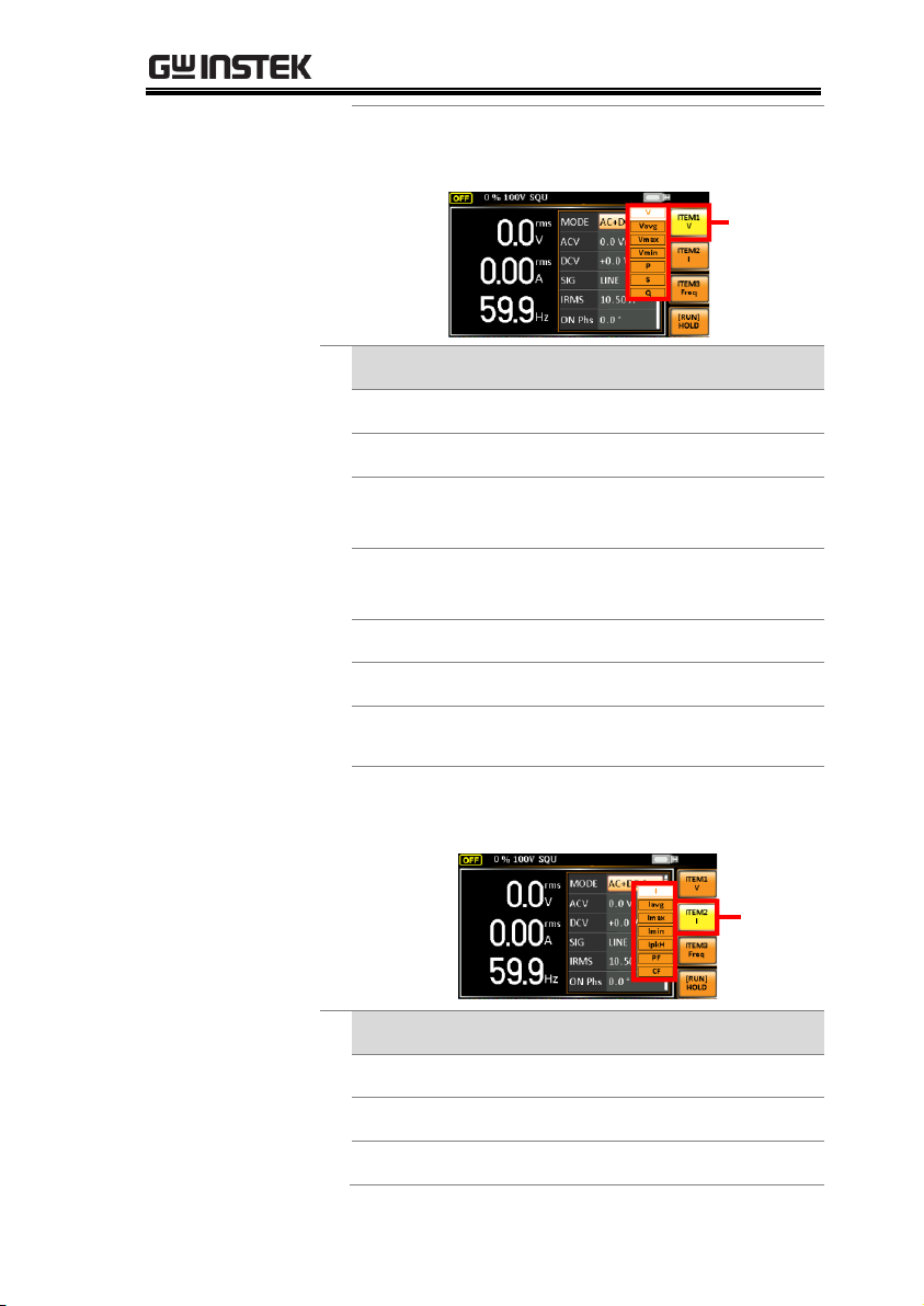
OPERATION
THDv
Total Harmonic Distortion Voltage
(available in AC-INT mode only)
Example of
ITEM1 in
AC+DCSync
ITEM1
options
ITEM 2
I Root Mean Square Current
Iavg
Average Current
Imax
Minimum Peak Value of Output
Current
Imin
Minimum Peak Value of Output
Current
IpkH
Peak Current Hold
PF
Power Factor (n/a in DC-INT mode)
CF
Crest Factor
(n/a in DC-INT mode)
THDi
Total Harmonic Distortion Current
(available in AC-INT mode only)
Example of
ITEM2 in
AC+DCSync
ITEM2
options
ITEM 3
P Real Power
S Apparent Power (n/a in DC-INT mode)
Q Reactive Power (n/a in DC-INT mode)
93
Page 94
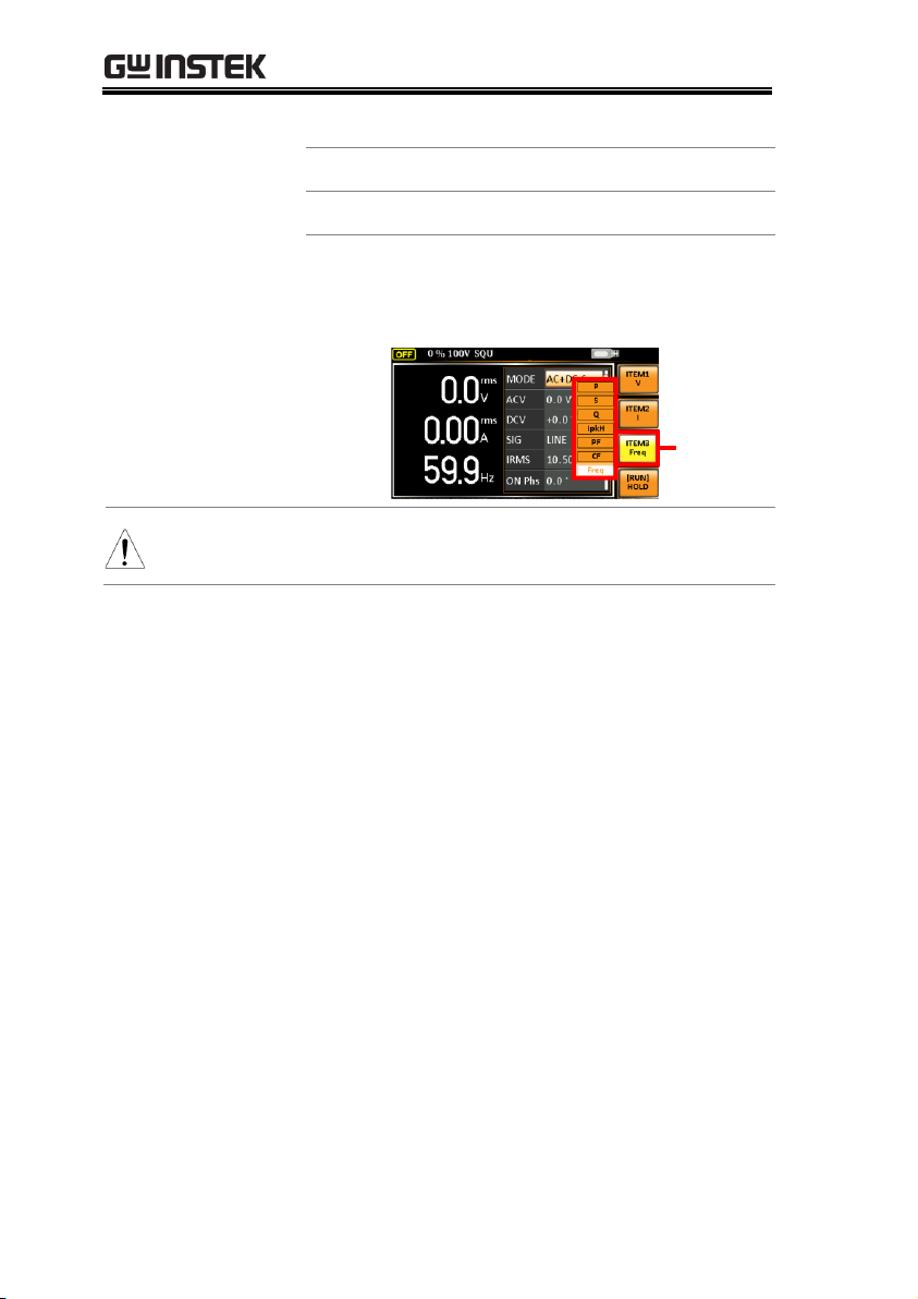
ASR-3000 Series User Manual
IpkH
Peak Current Hold
PF
Power Factor (n/a in DC-INT mode)
CF
Crest Factor (n/a in DC-INT mode)
Freq
Frequency
(available in AC+DC-Sync and AC-
Sync modes only)
Example
of ITEM3
in
AC+DCSync
ITEM3
options
Note
Each output mode has varied measurement functions
display. Refer to the above tables for detailed options.
94
Page 95

OPERATION
Steps
1. Press the Display key to switch to
the Simple display mode.
2. Press the F2 (RMS/AVG/PEAK)
soft-key to toggle among each
mode of format.
RMS
Root Mean Square value
AVG
Average value
PEAK
Peak value
Example
DC-INT Output Mode
RMS
Display
V & I
RMS
Values
AVG
Display
Vavg &
Iavg
Values
Switch the Measurement Format
The 3 measuring formats, RMS, AVG as well as PEAK, on the farright side within the simple display mode can be switched by user
anytime in the process of power output, thus offering an instant
readout of diversified calculations.
95
Page 96
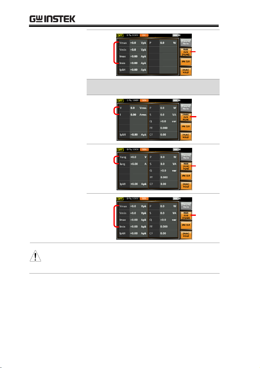
ASR-3000 Series User Manual
PEAK
Display
Vmax/
Vmin
&
Imax/
Imin
Values
All output modes except DC-INT
RMS
Display
V & I
RMS
Values
AVG
Display
Vavg &
Iavg
Values
PEAK
Display
Vmax/
Vmin
&
Imax/
Imin
Values
Note
The selected measurement format will be merely
shown in the Simple display mode, for which refer to
page 90 for further details.
96
Page 97

OPERATION
Activate the
Panel Lock
Press the Lock key to active the panel
lock. “Keys locked” appears on the
display.
A lock icon will appear in the upperright corner when the panel keys are
locked.
Disable the
Panel Lock
Hold the Lock key for ~3 seconds to
disable the panel lock. “Keys
unlocked” will appear on the
display and the lock icon will
disappear.
Example
Message
Lock icon
Panel Lock
The panel lock feature prevents settings from being changed
accidentally. When activated, all keys and knobs except the
Lock/Unlock key and the Output key (if active) will be disabled.
If the instrument is remotely controlled via the USB/LAN/RS232/GPIB interface, the panel lock is automatically enabled. See
page 170 for remote control details.
97
Page 98

Alarm Clear
Background
The ALM CLR (Alarm Clear) function will clear
alarms like Over Current, Over Peak Current,
PFC Error, DCDC Error, DCAC Error, Power
Input Anomaly, Fan fail, Remote Sense Error,
among others. Refer to page 197 for more details.
Steps
1. Press Shift + 6 to clear any alarms.
+
Example
Alarm message
ALM indicator
ASR-3000 Series User Manual
98
Page 99

OPERATION
WARNING
Both of these outputs are electrically linked. Only one
DUT should be connected to any one of the outputs at
a time. Using both outputs at the same time is not
supported. Using the front and rear outputs at the
same time could cause dangerous operating
conditions. See page 40 for details about using the
output terminals or sockets.
Turn Output On
Press the Output key. The Output key
will light up in orange and ON will be
displayed in the status bar to indicate
that the output is on.
Turn Output Off
Press the Output key. The Output
key light will go out and OFF will
be displayed in the status bar to
indicate that the output is off.
Turning the Output On/Off
When the output is turned on, the DUT can be connected to either
the rear panel output or the front panel output.
99
Page 100

ASR-3000 Series User Manual
WARNING
Ensure the output is off before handling the
remote sense connectors.
Use sense cables with a voltage rating exceeding
the isolation voltage of the power supply.
Never connect sensing cables when the output is
on. Electric shock or damage to the power supply
could result.
Remote Sensing
Input Connectors
Overview
The remote sensing input
connector is located at the rear
panel of the ASR-3000.
Local Sense
Operation
When using local sense, the remote sensing input
terminal is not used. No compensation of any
possible voltage drop seen on the load cables is
performed. Local sense is only recommended
when the voltage drop is of no consequence. By
default, the power supply is configured for local
sense.
1. Check that the remote sense setting is disabled
(page 130).
Advanced Settings
Using the Remote Sense Function → from page 100
Preset Settings → from page 103
Using the Remote Sense Function
The ASR-3000 can be operated using local or remote voltage sense.
By default, the power supply is configured for local sense.
Local Sense
100
 Loading...