

Instanta Limited ucd series Service Manual

1
INSTANTA LIMITED
S E R V I C E M A N U A L
ISSUE: 1- Dated: October 2009
“UCD” SERIES
AUTOMATIC FILL, UNDER-COUNTER HOT WATER DISPENSERS
CONTENTS
Section: Page No:
Contents p.1
Introduction p.2
Principle of Operation p.2
1 .0 Technical Specifications p.3
2.0 Installation Checklists p.4
3.0 The LCD Display p.5
4.0 Temperature Adjustment p.6
5.0 Water Dispense settings & adjustment p.6
6.0 Sensing Probes p.7 - 8
7.0 Thermistor p.7
8.0 Heating Elements p.8
9.0 Triac p.9
10.0 Printed Circuit Boards p.9 - 11
11.0 Transformer p.12
12.0 Hot Water Pump p.12
13.0 Hot Water Gate-Valve & Recirculation p.12 - 13
14.0 Thermal Cut-outs p.13
15.0 Solenoid Valve p.14
16.0 Hot Water Dispense Font p.14 - 15
17.0 Storage Tank p.15
18.0 De-scaling p.15 - 16
19.0 Fault-Finding p.17 - 18
20.0 Warning Messages p.19 - 20
21.0 Exploded Drawings & key p.21 - 24
22.0 Wiring Diagrams p.25 - 26

2
INTRODUCTION:
The “UCD” (formerly UCDB) series of under-counter hot water dispensers were
launched in August 2008. The new under-counter series have taken the proven
reliability and robust construction of the long-established counter-top boilers and
applied the latest advancements in electrical design and technology to produce an
appliance which is the most advanced of its kind and yet easy to use and built to
last.
The “UCD” series are inspected and tested in accordance with the company’s
ISO9001 Quality Management System and ISO14001 Environmental Management
System and conform with the protection requirements of the following standards
and specifications:
EMC W89/336/EEC Electro-Magnetic Compatibility (EMC)
EN 50-081-2 Generic Emission
EN 50-082-2 Generic Immunity
ROHS Manufactured in compliance with the requirements of the RoHS
Directive
All models in this range are similar in construction, but vary in size.
PRINCIPLE OF OPERATION:
When switched on, the machine first checks for water at the low-level (bottom)
probe. If no water is sensed, (as on initial switch-on following installation), the
solenoid is energised and cold water enters the tank. When water is detected at
the bottom probe, the heating element(s) is switched on to heat the water to the
correct temperature. When the set temperature is reached, the appliance is
“ready” for use and the counter-top dispense-font illuminates to indicate status.
Although the appliance is now ready for use, the solenoid continues to pulse
controlled bursts of water into the tank so that the temperature is maintained,
until the water level reaches the normal-operating probe.
Once water has reached the normal-operating probe, the appliance goes into ‘idle’
mode. The heating element is pulsed periodically to maintain temperature.
Hot Water is dispensed by pressing the illuminated push-button on the dispensefont. Depending on how the UCD appliance is programmed, either a measured
shot of water is delivered (volume adjustable within programme mode) or
alternatively, hot water can be dispensed for as long as the push-button is pressed
(on-demand set-up within programme mode). Note: It is not possible to dispense
hot water until the font push-button is illuminated “Hot” and the water has reached
the pre-set temperature (adjustable between 80 and 95^C within programme
mode).

3
1.0 TECHNICAL SPECIFICATION:
UCD-7
Voltage: 220-240V single-phase 50Hz
Supply: AC
Rated Input: 3.0kW
Fill Type: Automatic Fill
Recovery per Minute: 0.5 Litres (3KW)
Rapid Draw-off: 7.5 litres (21 pints)
Heat-up time: 33 minutes (from cold to full capacity)
Temp range: between 80 and 95^C
Height: 502 mm
Width: 280 mm
Depth: 380 mm
Avg. Power Consumption: 0.1 (kw/hour - standby)
UCD-12
Voltage: 220-240V single-phase 50Hz
Supply: AC
Rated Input: 3.0kW
Fill Type: Automatic Fill
Recovery per Minute: 0.5 Litres (3KW)
Rapid Draw-off: 12 litres (
Heat-up time: 20 minutes (from cold to full capacity)
Temp range: between 80 and 95^C
Height: 540 mm
Width: 360 mm
Depth: 415 mm
Avg. Power Consumption: 0.1 (kw/hour - standby)
UCD-47 and UCD-47/D
Voltage: 220-240V single-phase 50Hz
Supply: AC
Rated Input: 4.5kW [20A] or 6.75Kw [30A]
optional configuration
Fill Type: Automatic Fill
Recovery per Minute: 0.75 litre (4.5kW) or 1.2 litre (6.75kW)
Rapid Draw-off: 47 litres
Heat-up time: 11 minutes (from cold to full capacity)
Temp range: between 80 and 95^C
Height: 560 mm
Width: 465 mm
Depth: 500 mm
Avg. Power Consumption: 0.1 (kw/hour - standby)

4
2.0 INSTALLATION CHECKLIST:
The information below is useful in confirming that the UCD dispenser has
been installed correctly;
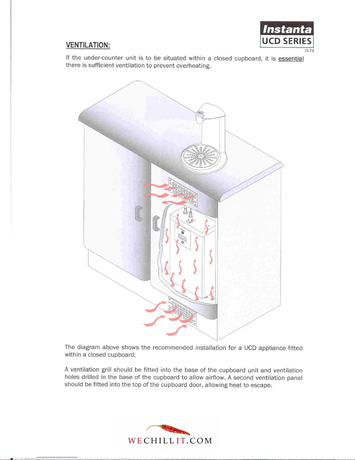
■ If the under-counter dispenser is being fitted into an enclosed cupboard, it
is essential that there is sufficient ventilation to prevent overheating.
For this type of installation, it is recommended that a ventilation grill be
fitted into the bottom of the cupboard and (if required) holes drilled in the
base of the cupboard to allow sufficient airflow. A second ventilation panel
should be fitted in the top of the cupboard door, allowing heat to escape.
■ The water dispense font must be fitted above the under-counter cabinet, or
within 1 metre of it.
■ Note: Duel-font dispenser (model: UCD47/D) has two water dispensing
fonts…each can be fitted up to 1 metre from the under-counter cabinet,
giving a maximum separation of 2 metres between the two counter-top
fonts.
■ On installation the water transfer tube should be cut to size (if too long), so
that the water has a more direct route and also preventing water from
trapping in the surplus tube.
■ The under-counter unit has an air-vent in the lid through, which occasional
wisps of steam are emitted in normal operation. If the under-counter
cabinet is well ventilated, these small amounts of steam will simply
disperse into atmosphere. However, if the under-counter cabinet is in a very
warm environment, maybe within a small enclosed cupboard, the steam
may cause condensation and/or damage to the underside of the countertop. To prevent this, it is recommended that a rubber vent tube be pushed
over the air-vent and directed (away from the counter-top) and preferably to
a permanent waste of if not, a condensing bottle.
■ The water dispense font must be sealed into the counter using a suitable
silicone sealant. This prevents moisture and spilt water from leaking
through to the under-counter cabinet.

5
3.0 THE LCD DISPLAY (Digital Program Menu):
The LCD display (located on the front of the under-counter unit) informs the user of
the boiler’s status (e.g. filling, heating, ready etc.). The display also informs the
user of potential fault conditions (e.g. no water supply, clean probes, etc.).
The LCD display in conjunction with the On/Off button also gives access to the
program menu which allows various settings to be selected.
To access the program menu:
• Switch the boiler off and back on again - within a few seconds of the boiler
being switched on again, press and hold the On/Off button in for
approximately 10 seconds, until the display reads “program mode”.
• Continue to press the On/Off button to proceed through the 26 menu
selections until the desired mode is reached.
• To select the mode, hold button in for 3 seconds.
• Program Menu is as follows:
1. Program Temp Set – [Sets temperature between 80 and 99^C]
2. Program Exit
3. Vend H/F1 – [Dispense Time for Font-A]
4. Vend C/F2 – [Dispense Time for Font-B – UCDB47/D models only]
5. Program Exit
6. Program M/C Type - M/C Type Under-Counter or M/C Type Counter Top (DB2000)
7. Program Eco Mode – [Enable or disable Eco mode]
8. Program Power Mode
9. Program Element (KW) – [3.0KW for UCDB3 & 12 – 4.75KW for UCDB47]
10. Program Lock Mode – [DB2000 only]
11. Program Open Time – [DB2000 only]
12. Program Drain Time – [determines the interval between each pump circulation]
13. Program Circulation Delay – [determines the amount of delay between the pump stopping
and the gate-valve closing to allow water to return back to lower unit]
14. Program Circulation Time – [determines how many seconds the pump operates to re-
circulate the water in the pipes, ensuring drinks always remain hot]
15. Program Check Keys - [DB2000 only]
16. Program Learn Keys - [DB2000 only]
17. Program Delete Keys - [DB2000 only]
18. Program Erase All - [DB2000 only]
19. Program Exit
20. Program Default CT - [DB2000 only] or Program Default UC – [all UCD models]
21. Program Supply In
22. Program Test Mode
23. Program ADC Values – Not Used
24. Program Bluetooth – Not Used
25. Program Zigbee – Not Used
26. Program Exit
PLEASE NOTE: New XE865 circuit boards are supplied with default settings for
DB2000 (counter-top) models. Therefore, when a new PCB is fitted to an UnderCounter appliance, the “PROGRAM M/C TYPE” mode must be set to M/C TYPE =
UC. In addition, the “PROGRAM DEFAULT” mode must be changed to “PROGRAM
DEFAULT UC”.

6
4.0 TEMPERATURE ADJUSTMENT:
The water temperature on the “UCD” series dispensers can be digitally adjusted
between a range of 80 and 95^Celsius in 1^C increments.
To adjust temperature, access the programme menu via the LCD display (see
Section-3). The factory-default temperature setting is 90^Celsius.
NOTE: For most end-users serving hot drinks, the optimum temperature setting will
be 90^Celcius for paper cups and 95^Celcius ceramic cups.
5.0 ADJUST WATER DISPENSE VOLUME:
The UCD dispensers can either be configured to deliver a measured volume of
water or alternatively, set up to dispense “on demand” (water dispensed for as
long as push-button is pressed). The factory default is “measured volume set at 6
seconds”.
The software measures the volume of water in time (seconds) NOT units of
measure.
To adjust volume/qty or change to “on-demand” …access the programme menu
via the LCD display (See section-3). Select menu option-3 (Vend H/F1). Press and
hold the On/Off button for three seconds to display the current dispense time.
Then use the On/Off button to increase dispense time and the Eco button to
decrease dispense time. When the desired time is set, press and hold the On/off
button for three seconds to store the new setting.
The UCD47/D model has duel dispense fonts, each can be independently set to
deliver different measured dispenses or alternatively, one font set to dispense a
measured volume and the other set to deliver “on demand”. To adjust, access the
programme menu as described above. Select menu option-3 (Vend H/F1) for FontA and menu option-4 (Vend C/F2) for Font-B.

7
6.0 THE SENSING PROBES:
Sensing probes are used to detect the presence of water within the tank (5-13
second response time), using a small electrical current to make a circuit via the
water.
They are made-up from a PTFE insulator with a chrome-plated brass rod through
the centre.
There are five level sensing probes inside the tank (from bottom to top):
1. Low-level Sensor - Yellow wire (CLEAN PROBES-1)
2. Eco Sensor [Not UCD7] - Grey wire (CLEAN PROBES-1)
3. Normal Operating Sensor - Brown wire (CLEAN PROBES-2)
4. De-scale warning Sensor - Orange wire (CLEAN PROBES-2)
5. Overfill detection Sensor - Red wire (CLEAN PROBES-2)
NOTE: Only the low-level and Normal Operating sensors are used in normal
operation.
Common problem: Hard-water in some parts of the UK causes a build-up of limescale on the sensing probes, which acts as an insulator (e.g. the sensor is nolonger able to detect the presence of water). When a sensor becomes insulated,
the water level will switch to a different sensor and the CLEAN PROBES message
will display. This will be followed by a number 1 or 2 (dependant on which sensor is
scaled-up – see above).
7.0 THE THERMISTOR (thermal resistor):
The thermistor is an electronic device used in place of a thermostat, to measure
the temperature of water. It is constructed using a thermally sensitive resistor
which exhibits changes in electrical resistance with even a slight change in water
temperature, making it extremely accurate (+/- 1.2 degrees Celsius).
On the “UCD” series, the thermistor is stuck to the outside of the tank-front using
metal-set putty.
POSITION: - IMPORTANT: THERMISTOR MUST BE BELOW THE LOW-LEVEL SENSOR –
USUALLY POSITIONED IN-LINE WITH THE ELEMENT TERMINALS.
Removal/replacement of thermistor: - To remove the old thermistor, chip it off
using the tip of a screwdriver.

8
To ensure that the new thermistor is correctly fitted to the tank, the metal-set
compound must be thoroughly mixed. To do this, fold the compound between your
fingers for at least one minute. Place the thermistor into the mixed compound and
apply the compound onto the cold tank,* ensuring that the head of the thermistor
is completely covered. The metal-set should completely harden in approximately 5
minutes.
* It is strongly advised that the tank should be cool before application of MetalSet
8.0 HEATING ELEMENT(S):
The heating elements are made from Incoloy800 material, which gives them a long
life expectancy. They are sealed into the tank by three blue silicone rubber
washers and secured by three 1/4”BSP brass lock-nuts.
UCD7 and UCD12:
ELEMENT RATING: 3KW, 230V
RESISTENCE: Between 19 and 20 Ohms
AMPS: The elements will draw between 10 and 11 amps.
UCD47 and UCD47/D:
ELEMENT RATING: 2.25KW, 230V
RESISTENCE: Between 19 and 20 Ohms
AMPS: The elements will draw between 6 and 7 amps.
If the element has blown it will have an open circuit. To test this use a simple PAT
test.
Boil-dry Protection:
Each element has a brazed “hot-return” fitting, which accepts a stud-mount,
120^C thermal cut-out switch. The live input to the element is directed through the
thermal cut-out switch. If the element overheats (boil-dry situation etc,), the
thermal switch picks up the rise in temperature and breaks the live supply to the
heater. If this happens, the thermal switch will need to be reset by pushing in the
small button on the top of the switch-body.
 Loading...