

Inspur Yingxin NX5440M4 User Manual

Dear users of Inspur Yingxin server,
Thank you for your choice of Inspur Yingxin server!
This manual describes the technical characteristics, system setting and installation method of Inspur
Yingxin server, and can help you learn more about it and use it easily.
Please send the packaging materials of our product to the recycling center, to facilitate pollution prevention
and benefit the mankind.
Inspur owns the copyright of this manual.
Without permission of Inspur, any unit or individual shall not copy this manual in any form.
Inspur reserves the right to modify this manual at any time.
The contents in this manual may be changed without notice.
If you have any questions or comments on this manual, please consult Inspur.
Inspur
December 2014
“Inspur “ and “Yingxin “ are registered trademarks of Inspur.
Other trademarks belong to respective registered companies.

2
Statement
Before you use this server officially, please read the following statement. Only after reading the following
statement and agreeing to the following terms can you begin to use this server. If you have any questions
about the following terms, please contact your supplier or contact us directly. If you do not raise any
objection but begin to use this server, it shall be deemed that you have agreed to the following terms and
conditions.
1. Special notes: At any time, you shall not modify any parameter in BIOS of this server other than those
allowable to be modified.
2. In case of any hardware failure of this server or if you hope to make any hardware upgrade, please
send your detailed hardware configuration information to our customer service center. Please do not
disassemble chassis of this server or any hardware device in the case.
3. As this server's memory, CPU, CPU radiator, fan, etc. are of special specifications, please do not mix
with corresponding devices of any other model of machine.
4. In case of any software problem during use of this server, you shall first contact teh corresponding
software provider, and especially contact us to facilitate communication and jointly solve the problems.
As for installation and operating of databases, network management software, or other networking
products, you shall handle in this way in particular.
5. If this server is installed on cabinet, please read the attached Quick Use Guide carefully. If you have
any problem, please contact our customer service center.
6. Attention: During use, back up your data if necessary.
7. Marks, names and copyrights of software and hardware products involved in this manual are owned
by the corresponding companies.
8. Term “we” in the above statement refers to Inspur; Inspur reserves the right to finally interpret the
above statement.

Notes for safe use
To ensure your personal safety and to avoid the risk of damaging the system and use environment, please
read this section carefully before installing or using, and strictly follow the requirements.
Note: To make better use of the equipment, you should pay attention to the following
precautions to avoid possible damage of components or data loss:
1. In case of any of the following circumstances, please unplug the power plug from the power socket,
and contact the customer service department of Inspur:
- The power cable, extension cable, or power plug is damaged.
- The equipment is splashed wet.
- The equipment falls off or is damaged.
- Any object has fallen into the equipment.
- The equipment does not work properly according to operating instructions.
2. If the system gets wet, please follow the following steps:
- Turn off the system and power supply, disconnect power sockets, and open the cover after 10 to
20 seconds.
- Move the equipment to a place with good ventilation conditions, and dry the system for at least
24 hours, to ensure that the system is completely dry.
- Close the host cover, reconnect the system to the power socket, and then boot.
- In case of operation failure or unexception, please contact Inspur to obtain technical assistance.
3. Pay attention to the positions of system cables and power cables, keep them away from being stepped
on or touched off, and ensure there are no other items on the cable.
4. Cool down the equipment before removing the cover or touching internal components. To avoid
damage to the motherboard, wait for five seconds after the system shuts down, and then remove the
components from the motherboard or disconnect peripheral system equipment.

4
5. If the modem, telecommunications or LAN options are installed, please pay attention to the following
matters:
- In case of thunder and lightening, do not connect or use a modem, or it may be struck by
lightning.
- Do not connect or use a modem in a wet environment.
- Do not insert the modem or telephone cable into the network interface controller (NIC) socket.
- Before opening the equipment packaging, touching or installing internal components, or touching
uninsulated modem cable or jack, disconnect the modem cable.
6. To prevent damage to electronic components within the device caused by electrostatic discharge,
please note the following matters:
- Remove the static electricity in body before disassembling and contacting any electronic
component within the device. You can remove static electricity by touching the metal grounded
object (such as an unpainted metal surface on the case) to prevent static influence on sensitive
components.
- Do not take the static-sensitive components not to be used out of antistatic packaging.
- Please regularly touch the grounding conductor or unpainted metal surface on the case, to remove
static electricity that can damage internal components.
7. When disassembling internal components upon consent of Inspur, please note the following matters:
- Turn off the system power supply and disconnect cables and any connected component. When
disconnecting the cable, please pull out the cable connector instead of pulling the cable.
- Before removing the cover or touching internal components, cool down the equipment.
- Before disassembling and touching any electronic component, touch the metal grounded object to
remove the static electricity on body.
- Do not disassemble excessively, to avoid damage of components or scratch arms.
- Handle components and plug-in cards carefully, instead of touching the components or contacts
on a card. When fetching a component or plug-in card, grasp its edges or metal mounting bracket.
8. When installing cabinet products, please note the following matters:
- Make sure that legs of the installed cabinet are fixed to the cabinet and are grounded, and all the
cabinet weight falls on the ground.
- Install components from bottom to top, and first install the most important components.
- Pull components out of the cabinet gently, to ensure the balance and stability of cabinet.
- Press the component slide release latch and slide the component in or out carefully, as slide
tcabinet may pinch your fingers.

- Do not make AC branch circuit in the cabinet be overloaded. Total cabinet load shall not exceed
80% of branch circuit rating load.
- Keep cabinet components in good ventilation conditions.
- When maintaining a component in the cabinet, do not step on any other component.
WARNING: The following warnings indicate the potential risks of property loss, personal injury or
death:
Warning 1: The system power supply may generate high voltage and hazardous electric energy, so as to
cause personal injury. Do not arbitrarily remove the host cover to disassemble and replace any component
inside. Unless otherwise notified by Inspur, only maintenance technicians trained by Inspur are authorized
to open the cover to disassemble and replace internal components.
Warning 2: Please connect the device to a suitable external power supply as indicated on the rated input
label. To prevent your equipment from damage by sudden rise or drop of voltage, please use the related
voltage stablization equipment or uninterruptible power supply equipment.
Warning 3: If extension cables must be used, please use the three-wire cable equipped with proper ground
connection plugs, view the rated values of extension cable, and ensure that the total rated current of all
products connected to extension cables do not exceed 80% of rated current limits of extension cables.
Warning 4: Be sure to use power supply components such as power lines and power sockets (if attached),
and do not arbitrarily replace any power cable or plug to ensure the safety of equipment and user.
WARNING 5: To prevent risk of electric shock caused by system leakage, please insert the power cables
of system and peripheral equipment into properly grounded power sockets. Please insert three-wire power
plugs into properly grounded three-core AC power sockets at arm’s length. Please use the grounding pins of
power line, rather than adapter plugs or grounding pins with unplugged cables. If the grounding conductor
is not installed and the situation of adequate grounding protection is unclear, do not use this equipment. You
can consult electricians.
Warning 6: Do not place any object into the system opening, becuase it might cause short circuit of
internal components and thus cause fire or electric shock.
Warning 7: Keep the system away from any radiator or heat source. Do not block the vent.
Warning 8: Do not leave any food or liquid inside the system or any other component. Do not use the
equipment in the environment of high humidity and high dust.

6
Warning 9: Use of a wrong type of battery might cause explosion. Before replacement of battery, please
consult the manufacturer and use the battery of same or similar type recommended by the manufacturer. Do
not disassemble, squeeze and puncture the battery or make its external contacts short out. Do not expose it
to the environment of fire or water, or the temperature exceeding 60 ℃. Do not attempt to open or maintain
the battery. Be sure to properly dispose spent batteries. Do not mix the spent batteries, the circuit boards
that may contain batteries, and other components and wastes. For battery recycling, please contact the local
recycling and disposal agency.
If you purchased a cabinet product, please read the installation instructions attached carefully,
understand specific warning statements and installation process, and follow the following precaution
measures to ensure the stability and security of the cabinet:
Warning 10: Before installing the device in the cabinet, please install front and side legs on a separate
cabinet first; for the cabinet connected to other cabinet, please install front legs first. If legs are not installed
accordingly before installation of devices in a cabinet, it may cause the cabinet turnover in some cases, so
as to cause personal injury. Therefore, please install the legs before installation of the devices in the cabinet.
After installation of equipment and other components in the cabinet, you can pull out only a component
through its sliding components one time. If several components are pulled out simultaneously, it may cause
the cabinet turnover and serious personal injury.
Warning11: Do not move the cabinet alone. Taking into account the height and weight of the cabinet, at
least two people should move the cabinet at the same time.
Warning 12: Statement
This is a Class A product that may cause radio interference in a life environment. In this case, the user
should take feasible measures.

About this Manual
● Product overview
● BIOS
● Install the operating system
● Integrated Raid System
● FAQ and troubleshooting
We recommend that you read this manual carefully before using the main chassis of this
server, in order to avoid unnecessary operation mistakes.
Technical Service Tel: 4008600011
Address: 1036 Langchao Road, Jinan City, China (Inspur)
Postal Code: 250101

8
Contents
Overview of NX5440M4 computing blade ..................................................................................................... 9
Technical specifications .......................................................................................................................... 9
Views....................................................................................................................................................... 9
Unit interfaces and indicator lights ....................................................................................................... 10
Use......................................................................................................................................................... 10
Jumper setting ....................................................................................................................................... 11
BIOS .............................................................................................................................................................. 13
How to enter BIOS setup interface ........................................................................................................ 13
BIOS System menu ............................................................................................................................... 13
Install the operating system ........................................................................................................................... 31
Manually install Windows Server2012 R2............................................................................................ 31
Manually install Red Hat Enterprise Linux 6.4 ..................................................................................... 35
Integrated RAID System ............................................................................................................................... 40
How to enter “SATA RAID configuration” interface ........................................................................... 40
Control key applications ........................................................................................................................ 40
SATA RAID setting .............................................................................................................................. 40
FAQ and troubleshooting .............................................................................................................................. 44
Reboot ................................................................................................................................................... 44
Boot problems ....................................................................................................................................... 44
Other notes ............................................................................................................................................ 47
Technical support .................................................................................................................................. 48

9
Overview of NX5440M4 computing blade
Technical specifications
Processor
Processor type
1 -2 Intel®Xeon Haswell-EP series processors
Platform
Platform type
Grantley-EP 2S Platform
Memory
Memory type
Memory slots
Total memory capacity
DDR4-1600/1866/2133 ECC Registered
8
Supporting maximum 512GB
Display controller
Controller type
Integrated display card
Hard disk controller
SATA controller supports 2 2.5-inch hot-swap SATA / SSD hard
disks
Views
Views are as shown in Fig. 1-1:
Fig. 1-1 Computing Blade
Overview of NX5440M4 computing blade
10
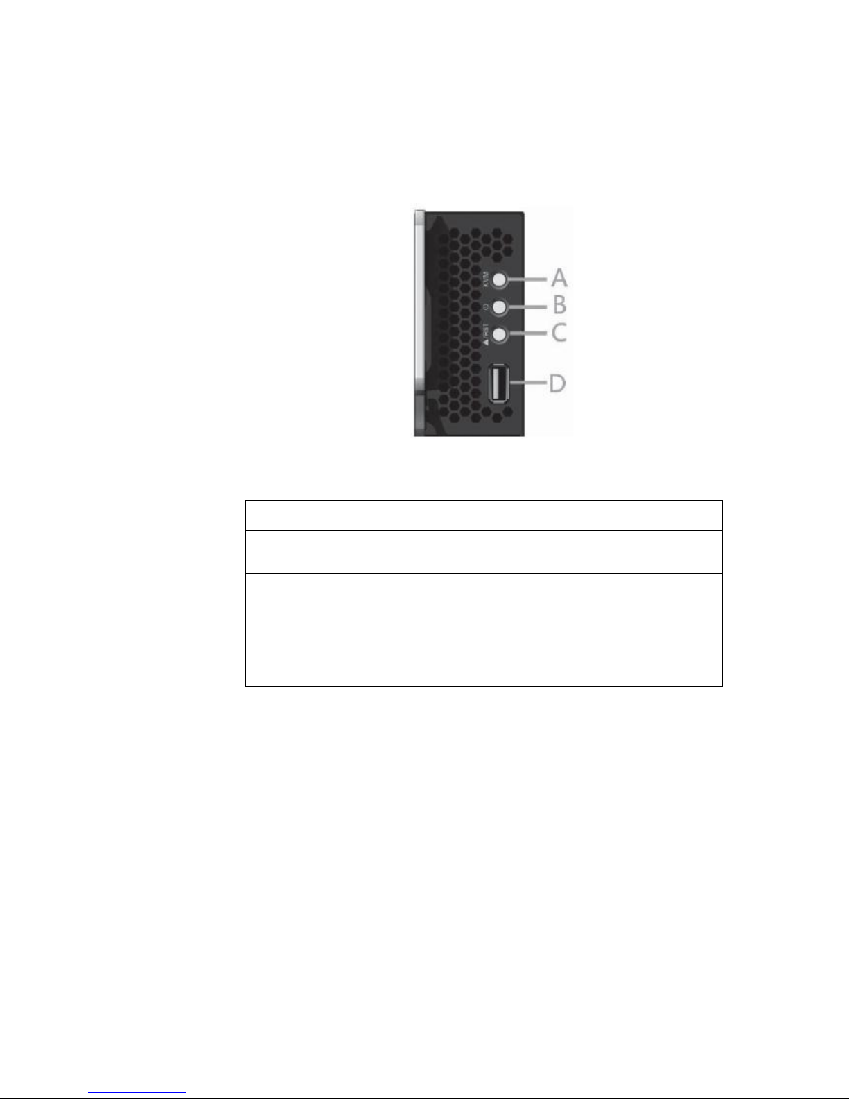
Unit interfaces and indicator lights
Fig. 1-2 Unit Interfaces and Indicator Lights
No.
Name
Status /function
A
KVM status indicator
light/key
Blue when KVM blade is activated/manually
activate the current blade
B
Power key/power supply
indicator light
Switch blade module/light on when normally
working, and green flickers when BMC is enabled
C
Reboot key/fault indicator
light
Reboot blade module/red flickers in case of any
blade fault
D
USB interface
Connecting USB equipment
Use
NX5440M4 computing blades must be installed in the Inspur I8000 server system for
use. For the installation method, please refer to relevant parts of I8000 server user
manual or the schematic diagrams pasted on the I8000 blade server chassis. Here, we
will talk about it any more.
Overview of NX5440M4 computing blade
11
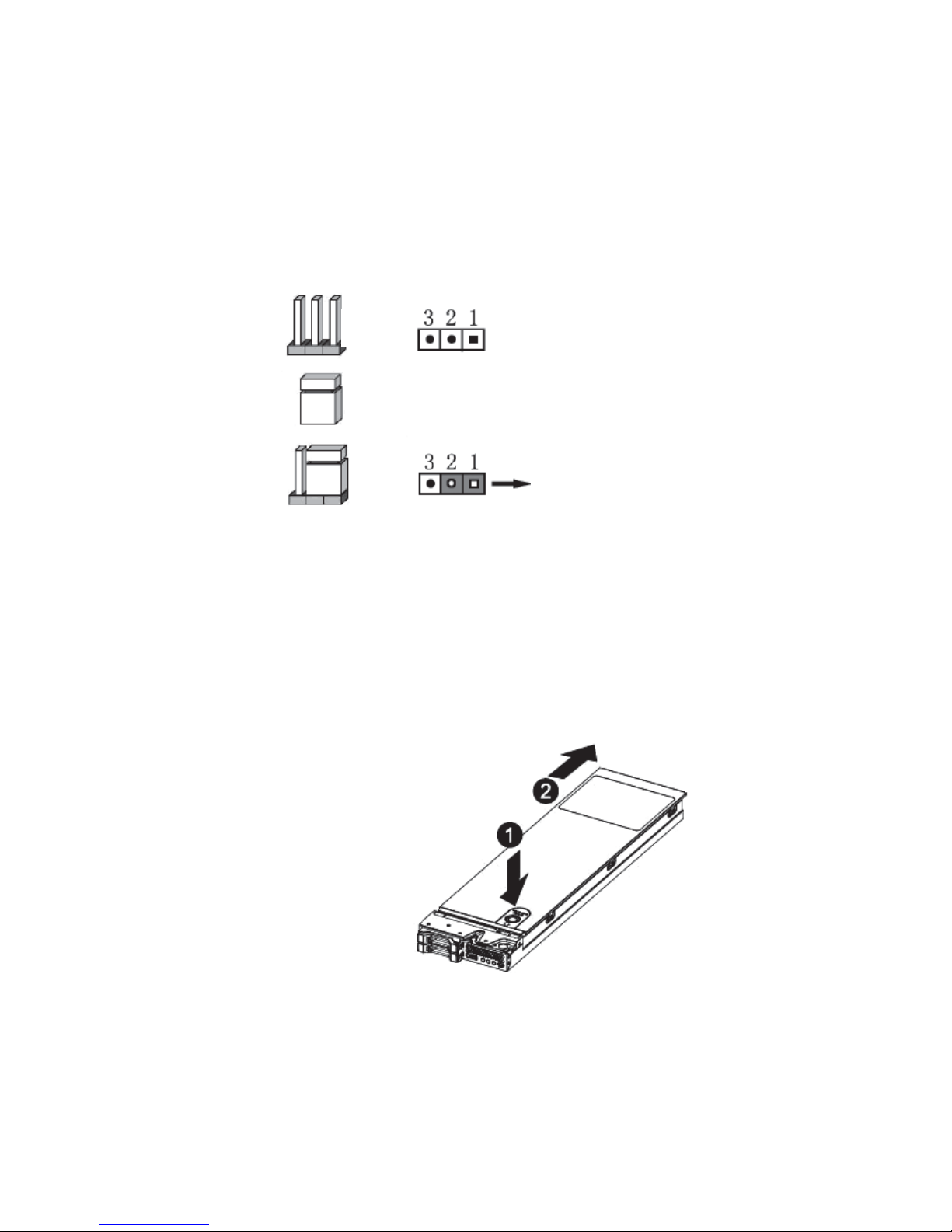
Jumper setting
Mainboard jumper setting aims to change interface functions through short-circuit
connection of two jumper pins, so as to adjust mainboard functions, as shown below.
Fig. 1-3 Jumper Setting
Open the upper panel of chassis
Any change of mainboard jumper shall be authorized by Inspur. Open the upper panel
of chassis according to the following steps:
1. Close system, pull out the blade module, press and hold deblocking shrapnel;
2. Push out towards the arrow direction, to remove the upper panel of chassis.
Fig. 1-4
Pin
Jumper cap
Setting
Select pins 1 and 2 for
short-circuit connection
Overview of NX5440M4 computing blade
12
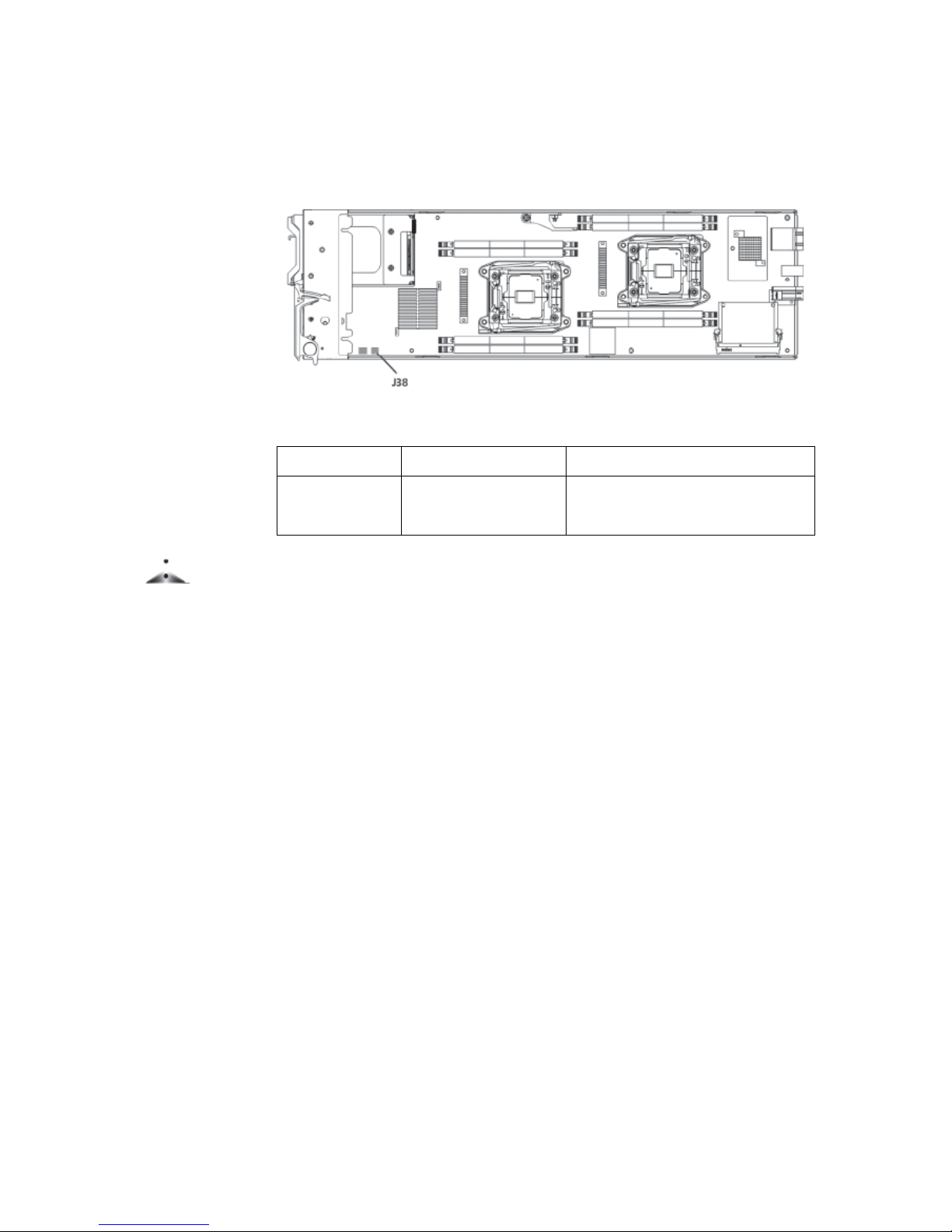
Clear CMOS jumper
Fig. 1-5 Jumper Position
Jumper No.
Description
Functions
J38
CMOS Clear jumper
Pin 1-2 short-circuit connection, normal
status; Pin 2-3 short-circuit connection,
Clear CMOS.
Notes
Clear CMOS, and wait for 5 seconds after short-circuit connection of Pin2-3; then
conduct short-circuit connection of Pin1 and Pin2 stitches of CLR_CMOS jumper
with the jumper cap again (default setting status), and recover original status.
13
BIOS
How to enter BIOS setup interface
Switch on and boot this server, to start system boot. If the prompt of “Press <DEL> to
SETUP or <TAB> to POST” appears at the bottom of screen, press DEL, wait and
enter the “BIOS setup” interface.
In case of failure to enter, please press Ctrl-Alt-Del simultaneously, and reboot.
Repeat the above operations (If you press the DEL key when seeing the prompt, you
should complete operation as soon as possible).
Notes
Some BIOS options can not be set, such as automatic system test and configuration.
Select the rightward pointer in front of some option, and press Enter key, cascading
menus ( namely sub-menus ) will be displayed.
BIOS System menu
This chapter mainly introduces the following function menus of BIOS, and notes.
Function menus:
Menu
Function
Main
Setting basic system options such as system time and system date, and
displaying the information of BIOS, memory, etc.
Advanced
Setting advanced features of serial port redirection, PCI bus, CSM
module
IntelRCSetup
Setting memory mode, CPU properties, power dissipation management,
QPI speed, IIO module, ME module,
PCH module, etc.
Server Mgmt
Display BMC network configuration parameters
Boot
Setting boot sequence of system devices
Security
Setting system administrator and user password
Save &Exit
Save BIOS setup, and exit BIOS setup, etc.

BIOS
14
Operation key description:
Key
Description
↑ (Up key)
Select the previous menu or value
↓ (Down key)
Select the next menu or value
← (Left key)
Select the left menu or value
→ (Right key)
Select the right menu or value
Esc key
Back to the previous menu or exit BIOS setup interface
+ key
Change the option value. Change the value of current menu option to the
previous option value. This key only display the values related to this
option, rather than all option values
- key
Change the option value. Change the value of current menu option to the
next option value. This key only display the values related to this option,
rather than all option values
F1 function key
Help hotkey, can display relevant description of current menu
F9 function key
Recover the default setting for the best performance
F10 function key
Save CMOS setting and exit
Enter function key
Execute current command or enter sub-menus
Statement:
Here, we introduce only common BIOS options, which you need not or should not set.
We will not talk about them any more.
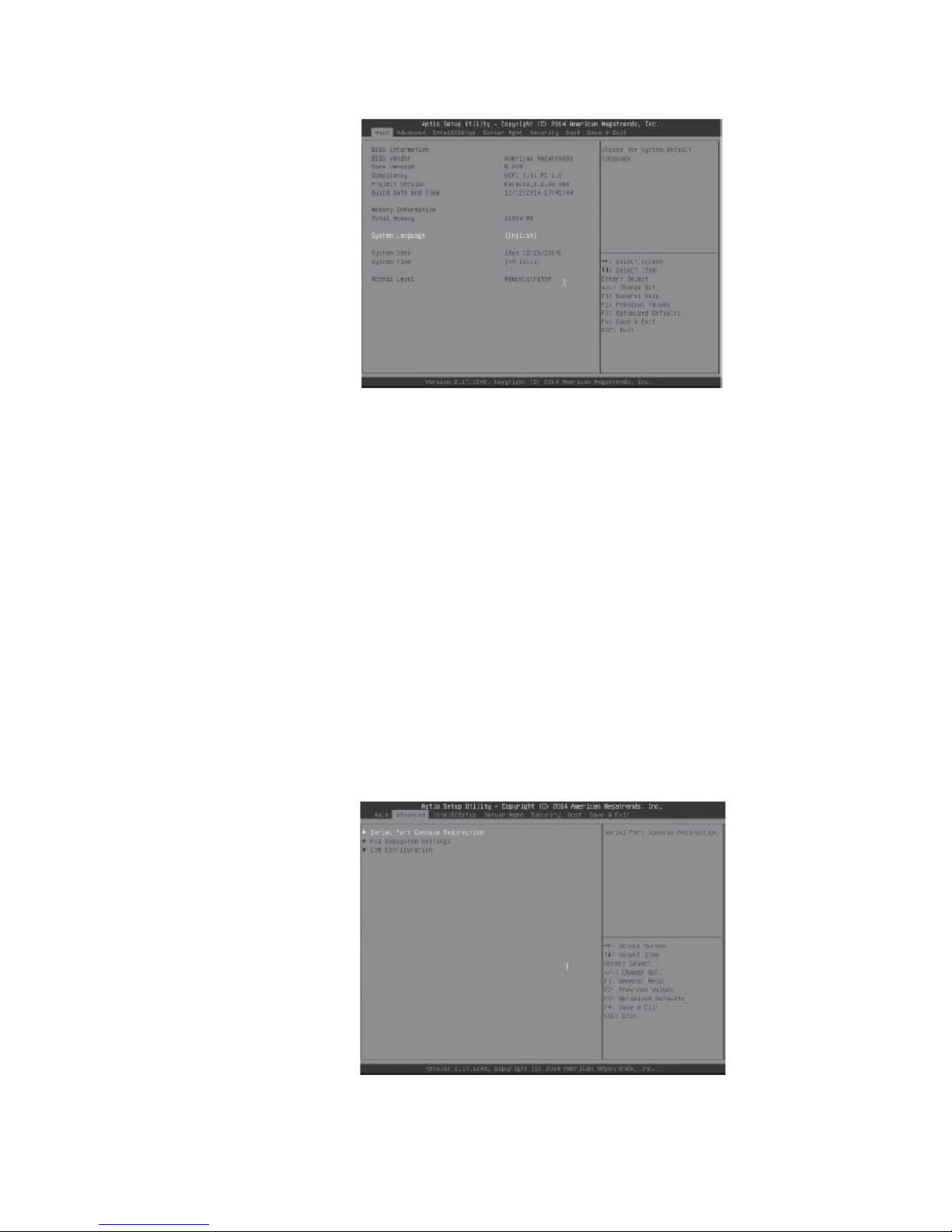
Main menu
In the BIOS setup, Main menu is first displayed, through which a user can view BIOS
version and memory capacity, and also set system time and date, etc.
BIOS
15
Fig. 2-1
● BIOS Information
Display BIOS version, BIOS change time.
● Memory Information
Display system memory capacity size.
● System Date
Setting system date in the format of week/ month /day /year.
● System Time
Set system time in the format of hour/minute/ second (24 hours).
Advanced menu
Fig. 2-2
 Loading...