

Inspur Tiansuo TS860 User Manual

Dear User of Inspur Tiansuo Server:
Heartfelt thanks to you for using Inspur TS Server.
This manual introduces technical features, system setup and installation,
which facilitate you to fully understand and expediently use this server.
Please deliver the package of our product to the waste recycling station,
in favor of pollution prevention and humankind benet.
This manual is the property of Inspur.
This User Manual is not to be copied by any group or person in any
manner without the consent of Inspur. Inspur reserves the right of revising
this manual at any time.
Any alteration about the content of this manual will not be informed.
Please contact Inspur if you have any questions or advice about this
manual.
Inspur
August, 2014
“Inspur” is the registered trademark of Inspur Group Co., Ltd.
Other trademarks respectively belong to their corresponding registered
corporations.

Statements
Please read the following statement before you use this server formally. Only
when you have read this statement hereinafter and agreed the following terms, you can
formally use this server. If you have any questions about the following terms, please
contact our supplier or us directly. If you have no questions about these terms and start
to use this server, it acquiesces that you have agreed the following terms.
1. We must call your attention that you must not alter any other parameters in
the main board BIOS of this server at any time, except for the parameters which we
indicate that you can alter.
2. If there are any hardware problems when you use this server, or you wish
to upgrade the hardware, please feedback the detailed hardware configuration of
your machine to our Customer Service. Don’t disassemble the server chassis or any
hardware components in the chassis by yourself.
3. In this server, the MEMORY, CPU, CPU Heat Sink and Fan are in given standard.
Please don’t mix them with the corresponding components of any other machines.
4. When you have any software problems during the application of this server,
we hope that you firstly contact the corresponding software supplier and then he
shall contact us in favor of communication so as to solve your problem together. We
sincerely hope you can do this especially when you confront with the installation and
running problem of database, network management software or other networking
products.
5. Please rstly read the attached Brief User Guide when you install this server.
Please contact our Customer Service Center if you have any questions about the
application.
6. We must call your attention: please do necessary data backup in your
application process.
7. This is a Grade A product, and may induce radio interference in the living
environment, in which case the user may be required to take adequate measures.
8. The copyrights of the markers and names of the software and hardware product
referred in this manual are the property of corresponding companies.
9. In the above statement, “us” indicates the Inspur; Inspur reserves the right of
nal explanation about the above statement.

Regarding the Manual
● Safety Information
This chapter introduces the safety information regarding server usage.
● Brief Introduction
This chapter introduces module assembly, technical features, appearance and I/O
interface specications, etc, of the whole server.
● System setup
This chapter introduces the settings of BIOS.
● Install OS
This chapter introduces how to install the mainstream OS on this server.
● Instructions on integrated management functions
This chapter introduces how to use the management functions integrated by the
management card.
● OLED usage introduction
This chapter introduces the functions and usage of OLED.
● Common problems and troubleshooting
This chapter introduces some measures for common problems.
We suggest you read this manual carefully before you use this server for fear of
unnecessary faults during your operation.
Technical service:4008600011
Address:No.1036 Langchao Road, Jinan Shandong 250101, P.R.China (Inspur)
Postcode:250101

CONTENIDO
Chapter One Safety Information ............................................................................... 1
Chapter Two Brief Introduction ................................................................................ 6
2.1 System module installation ............................................................................ 7
2.2 Technical Specications ................................................................................. 9
2.3 Front view ...................................................................................................... 11
2.4 Rear view ........................................................................................................ 14
2.5 Start the server ................................................................................................ 15
2.6 Close the server .............................................................................................. 16
Chapter Three System Setup ..................................................................................... 17
3.1 System BIOS setup ......................................................................................... 17
3.2 Clear CMOS ................................................................................................... 28
Chapter Four Operating System Installation ........................................................... 30
4.1 Manually Installation of Windows Server 2012 ............................................. 30
4.2 Manually Installation of Red Hat Enterprise Linux 6.4 ................................ 34
Chapter Five Integrated management function introduction ................................. 39
5.1 Remote login .................................................................................................. 39
5.2 Function menu introduction ........................................................................... 40
Chapter Six OLED usage introduction ..................................................................... 53
6.1 Connect BMC ................................................................................................. 53
6.2 Menu interface ................................................................................................ 55
6.3 Other interfaces .............................................................................................. 57
Chapter Seven Common Problems and Troubleshooting ....................................... 59
7.1 Restarting the Server ...................................................................................... 59
7.2 Problems When Starting the Machine ............................................................ 59
7.3 Additional Notes ............................................................................................. 63

1
!
Chapter 1 Safety Information
Warning: the following warnings show that there are potential dangers
that may cause property loss, personal injury or death:
Warning 1: The power supply equipment in the system may generate high
voltage and dangerous electrical energy and thus cause personal injury. Please do
not dismount the cover of the host or to dismount and replace any component in
the system by yourself, unless otherwise informed by Inspur; only maintenance
technicians trained by Inspur have the right to disassemble the cover of the host,
dismount and replace the internal components.
Warning 2: Please connect the equipment to appropriate power supply, and
the power should be supplied by external power supply which is indicated on the
rated input label. To prevent your equipment from damages caused by momentary
spike or plunge of the voltage, please use relevant voltage stabilizing equipment or
uninterruptible power supply equipment.
Warning 3: If extended cables are needed, please use the three-core cables
matched with correct earthed plug, and check the ratings of the extended cables to
make sure that the sum of rated current of all products inserted into the extended
cables do not exceed 80% of the limits of the rated currents of the extended cables.
Warning 4: Please be sure to use the supplied power supply component, such
as power lines, power socket (if supplied with the equipment), etc. For the safety of
equipment and the user, do not replace randomly power cables or plugs.
Warning 5: To prevent electric shock dangers caused by leakage in the
system, please make sure that the power cables of the system and peripheral
equipment are correctly connected to the earthed power socket. Please connect the
three-core power line plug to the three-core AC power socket that is well earthed
and easy to access, be sure to use the earthing pin of power lines and do not use
the patch plug or the earthing pin unplugged with cables. In case of the earthing
conductors not installed and it is uncertain whether there are appropriate earthing
protections, please do not operate or use the equipment. Contact and consult with
the electrician, please.
Warning 6: To avoid short circuit of internal components and re or electric

Chapter 1 Safety Information
2
shock hazards, please do not ll any object into the open pores of the system.
Warning 7: Please place the system far away from the cooling plate and at
the place with heat sources, and be sure not to block the air vents.
Warning 8: Be sure not to scatter food or liquid in the system or on other
components, and do not use the product in humid and dusty environment.
Warning 9: The replacement of batteries with those of another model may
cause explosion. When replacement of batteries is required, please consult rst the
manufacturer and choose batteries of the same or a similar model recommended
by the manufacturer. Do not dismount, extrude and pink the batteries or make the
external connection point short circuit, and do not expose them in the environment
over 60°C. Never throw them into re or water. Please do not try to open or repair
the batteries, and be sure to reasonably deal with the flat batteries and do not
put the at batteries, the circuit boards that may include the batteries and other
components with other wastes. For relevant battery recovery, please contact the
local waste recovery and treatment mechanism.
If what you bought is the chassis, besides carefully read the installation
description attached with the cabinet products and get known about the special warning
notices and installation process, you must abide by the following preventive measures
to guarantee the cabinet to be stable and safe:
Warning 10: Before installing equipment in the chassis, please install front
and side supporting feet on the independent chassis; for cabinet connecting with
other chassis, it shall install the front supporting foot first. If you fail to install
correspondingly the supporting foot before installing equipment in the chassis,
it may cause the cabinet to turn over in some cases, and thus may cause personal
injury. Therefore, it is necessary to install supporting feet before installing
equipment in the chassis. After installing the equipment and other components in
the chassis, it can only pull out one component from the cabinet through its sliding
component at one time. Pulling out several components at the same time may lead
the cabinet to turn over and cause serious personal injury.
Warning 11: Please do not move the chassis. Considering the height and
weight of the chassis, at least two people are needed to complete its movement.
Warning 12: Declaration
The product is Grade A product, and in the living environment, it may cause

Chapter 1 Safety Information
3
radio jamming. In such case, it may need the user to take feasible measures for the
interference.
Notes: in order to help you use the equipment, the following considerations can
help avoid the occurrence of problems that may damage the components or cause data
loss:
1. In case of the following cases, please unplug the power line plug of products
from the power socket and contact the customer service department of Inspur:
- The power cables, extended cables or power plugs are damaged.
- The products get wet by water.
- The products have fallen off or been damaged.
- Objects fall into the products.
- When operating according to the operation instructions, the products cannot
function normally.
2. If the system becomes damp, please treat it according to the following steps:
- Switch off the power supplies of the system and the equipment, disconnect them
with the power socket, wait for 10 to 20 minutes, and then open the cover of the host.
- Move the equipment to the ventilation place to dry the system at least for 24
hours and make sure that the system is fully dried.
- Close the cover of the host, re-connect the system to the power socket, and then
start the equipment.
- In case of operation failure or abnormal situation, please contact Inspur and get
technical support.
3. Pay attention to the position of the system cables and power cables, wire them
in places not to be stepped on or knocked down and ensure not to place other objectives
on the cables.
4. Before dismounting the cover of host or contacting the internal components,
you shall cool down the equipment first; to avoid damaging the main-board, please
power off the system and wait for 5 seconds, and then dismount the components from
the main-board or disconnect the connection of peripheral equipment of the system.
5. If there are modulator-demodulator, telecommunication or local area network
options in the equipment, please pay attention to the following matters:
- In case of thunder and lightning weather, please do not connect or use the
modulator-demodulator. Otherwise, it may be subject to lightning strike.

Chapter 1 Safety Information
4
- Never connect or use modulator-demodulator in moist environment.
- Never insert the modulator-demodulator or telephone cables to the socket of
network interface controller (NIC).
- Before unpacking the product package, contacting or installing internal
components or contacting un-insulated cables or jacks of the modulator-demodulator,
please disconnect the modulator-demodulator cables.
6. In order to prevent the electrostatic discharge from damaging the electronic
components in the equipment, please pay attention to the following matters:
- You shall conduct off the static electricity on the body before dismounting or
contacting any electronic component in the equipment. You can conduct off the static
electricity on the body by contacting the metal earthing objects (such as the unpainted
metal surface on the chassis) to prevent the static electricity on the body from
conducting itself to the sensitive components.
- For electrostatic sensitive components not ready to be installed for application,
please do not take them out from the antistatic package materials.
- During the work, please touch the earthing conductor or the unpainted metal
surface on the cabinet regularly to conduct off the static electricity on the body that
may damage the internal components.
7. When dismounting the internal components with the approval of Inspur, please
pay attention to the following matters:
- Switch off the system power supply and disconnect the cables, including
disconnecting any connection of the system. When disconnecting the cables, please
grab the connector of cables and plug it out, and never pull the cables.
- Before dismounting the cover of cabinet or touching the internal components,
the products need to be cooled down.
- Before dismounting and touching any electronic component in the equipment,
you shall conduct off the static electricity on the body by touching the metal earthing
objectives.
- During the dismounting process, the operation shall not be too big, so as to
prevent damage to the components or scratching of the arms.
- Carefully deal with the components and plug-in cards, and please never touch
the components or connection points on the plug-in cards. When taking the plug-in
cards or components, you should grab the edges of the plug-in cards or components or

Chapter 1 Safety Information
5
their metal xed supports.
8. During the process of cabinet installation and application, please pay attention
to the following matters:
- After the installation of cabinet is nished, please ensure that the supporting feet
have been xed to the rack and supported to the ground, and all weight of the rack have
been fell onto the ground.
- It shall install into the cabinet according to the sequences from the bottom to the
top, and rst install the heaviest component.
- When pulling out the components from the cabinet, it shall apply force slightly
to ensure the cabinet to keep balance and stabilization.
- When pressing down the release latch of the sliding rail of components and
sliding in or out, please be careful, as the sliding rail may hurt your gures.
- Never make the AC power branch circuit in the cabinet overload. The sum of
cabinet load shall not exceed 80% of the ratings of branch circuits.
- Ensure that components in the cabinet have good ventilation.
- When repairing components in the cabinet, never step on any other components.
6
Chapter 2 Brief Introduction
Inspur TS860 is an 8U large-scale rack server, which can support 8*Intel Xeon
E7-88XX V2/V3 processors, compatible with E7-48XX V2/V3 processors (only single
4-socket and dual partition configuration support); It supports 192*DDR3/DDR4
RDIMMS in maximum and 6TB system memory. If adopting 64GB LRDIMM, it can
support 12TB. TS860 possesses the characteristics of high-performance, high reliability
and easy expansion and management, meeting the demands of high-end industry’s core
business applications.
Warning!
Due to the large packed weight, the professional forklift machine should be used
in moving the shipping container. If you move manually, there should be at least 4
people operating simultaneously. Ignoring the warning may result in serious personal
injury.
Notes:
If you want to put the server into the cabinet through guide rail or the
tray, you must first install the host chassis into the cabinet for safe
operation because of the heavy product, and then put the computing
module into the host chassis.
At least 3 people are needed during the server installation operation.
There is detailed operation instruction about the disassembly and
assembly of modules and components on the side of host chassis cover
for the reference of maintenance or expansion.
Chapter 2 Brief Introduction
7
To ensure the system’s cooling effect, please uncover the film on the
cover plate of the server and then power up the server to use.
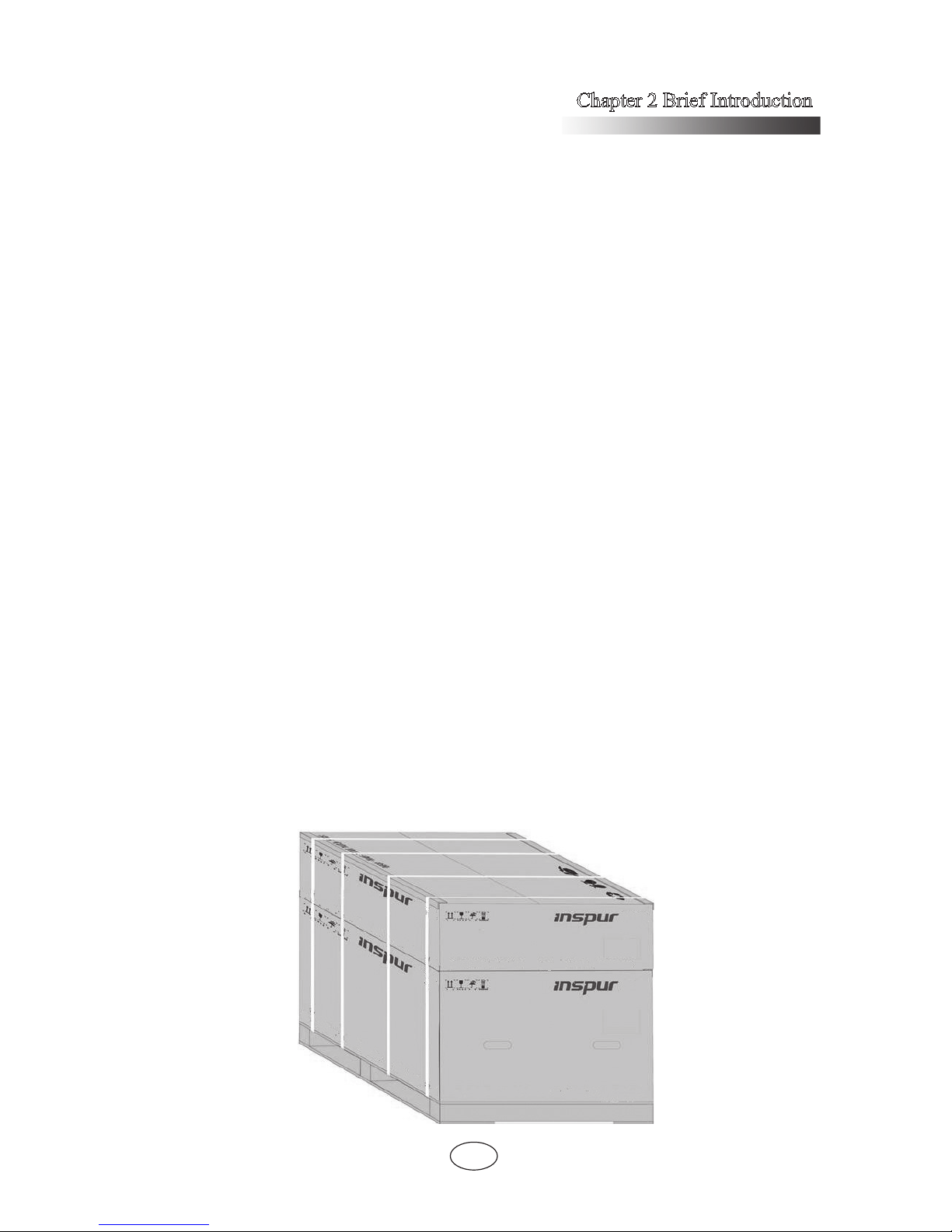
System module installation
The host chassis and computing modules of your TS860 server system are packed
separately to ensure the transportation safety. Host chassis and computing modules
boxes are stacked on the wooden pallet, and bound with packing tape and stretch lm,
showing as follows.
After the arrival of the goods, please remove the winding stretch film, packing
tape, angle bead, and then take down the boxes with computing modules from the host
packaging box.
Notes:
1. Please rstly install the separately-packaged computing modules into the host
chassis before ofcial usage.
2. Before unpacking the product, it is necessary to confirm the correspondence
between host chassis box and computing module box according to the labels on the
packaging box. Install the host chassis and computing module with the same serial
numbers and do not mixed; otherwise the system will not function properly.
3. During the installation and dismantlement of machine modules, you should
wear the attached anti-static gloves to protect components from electrostatic damage;
the anti-static gloves are placed in the general accessories box in the host chassis box.

Chapter 2 Brief Introduction
8
Unpack host
1. Split the tape seal on the box with paper cutter and take out host panel, power
cord and accessory box on the pad in the box for later use, and then remove the pad
from the box.
2. Take out the rails on the side of the host from the box.
3. Take out the host packaging plastic bag and place the host on the working table.
Note: If you plan to install the server in the cabinet, you can use the attached guide
rail to realize the installation after carrying out the host.
Unpack computing modules
TS860 server system includes two computing modules which are packaged using
seperate pad. Then 2 processing modules are packaged by carton as whole.
1. Split the tape seal on the box with paper cutter and take out the pad on the 2
separately-packaged computing modules.
2. Take out the computing module from the box and then take out the anti-static
bags, and the serial number of each computing module can be identied by the label on
the left side of modules.
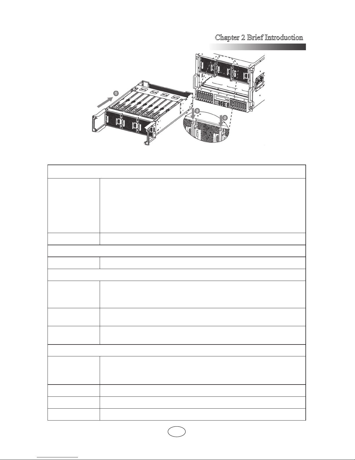
Install computing module
Note: Each server is congured with two computing modules. Please install them
into the upper computing module slot and lower slot respectively according to the label
instruction on the computing module box. The computing module-2 should be installed
into the upper computing module slot, and the computing module-1 should be installed
into the lower computing module slot.
1. Lift the module to insert its back horizontally into the module slot of chassis,
and evenly force it back into the chassis and pull the handle to the straight position at
the same time.
2. After pushing the computing module into the bottom of the chassis, turn over
the handle on both sides of the module to let the hook fully locked.
3. Finally, install the front panel to the chassis.
Chapter 2 Brief Introduction
9
Technical Specications
Processor
Processor type
1. Intel Xeon E7-88XX V2 series processor, compatible with E7-48XX
V2 series processor (only single 4-socket and dual partition support)
2. Intel Xeon E7-88XX V3/V4 series processor, compatible with E748XX V3/V4 series processor (only single 4-socket and dual partition
support)
Note: V3/V4 series CPU can only be used with DDR4 memory.
Interface LGA2011
Chipset
Chipset type Intel C602J
Memory
Memory type
1. DDR3 ECC Registered memory
2. DDR4 ECC Registered memory
Note: DDR4 memory can only be used with V3/V4 series CPU.
Memory slot Qty.
Support to extend 16 memory boards, each supporting 12
memory slots
Total memory
capacity
Support Max.6TB ECC DDR3/ ECC DDR4 memory(RDIMM)
If using 64GB LRDIMM, it can support max.12TB.
I/O Port (1*I/O Riser)
USB port
2*rear USB port
4*front USB port (only two available when it is non-dual partition mode
and single IO Riser is used)
Serial port 1*front RJ45
Network port 4*RJ45
Management port 1*special RJ45
Chapter 2 Brief Introduction
10
Display port 1*rear VGA
Display controller
Controller type Integrated AST2300
Video memory 16MB
HDD controller
SATA controller (1) IO Riser, integrated 2*M-SATA
RAID External SAS RAID card, support RAID0/1/5/6
NIC
NIC controller
0/1/2/3
(1*I/O Riser) integrated Intel I350 4-port Gigabit network adapter
PCI expansion slot
PCI bus type PCI-Express bus, support FH/HH expansion card
PCI-E slot
Support max.26*PCI-Express 3.0 slots:
Each basic IO module can support 2*PCIE slots: 1*PCIE x8, 1*PCIE
x16;
Each expansion IO module can support 10*PCIE slots: 5*PCIEx8,
5*PCIE x16;
The 5*PCIE x16 slots of extended IO module only have the performance
of x8;
Storage control module supports 2*PCIE x8 slots (only HH expansion
card supported);
RAID card can only be installed in the PCIE slots of the storage control
module;
GPU can only be installed in the PCIE x16 slot of the basic IO module.
HDD
HDD type 2.5-inch SAS/SATA/SSD HDD
Quantity
Support max.16*2.5-inch HDD
Each IO Riser card can support 2*M-SATA HDD
External memory driver
CD-ROM USB CD-ROM (optional)
Inspur USB drive Inspur USB drive (optional)
Power supply
Specication
Support 8*800W redundant power supply module, support N+N/N+M
redundancy(N Min.3)
Chapter 2 Brief Introduction
11
Power input Please refer to the specication in the host nameplate label.
Physical specications
External
dimension of
packing case
Host machine: 1168mm × 722mm × 587mm (depth x width x height)
Module:1168mm × 721mm × 279mm (depth x width x height)
Overall
dimension
W(width): 444mm; H(height): 352mm; D(depth): 830mm
Weight
Host machine (package) gross weight: 71.5Kg
Module (package) gross weight: 58Kg
Environmental parameters
Operating
temperature
5℃-40
℃
Storage and
shipping
temperature
-40℃-55
℃
Operating
humidity
35%-80% relative humidity
Storage and
shipping
humidity
20%-93%(40℃) relative humidity
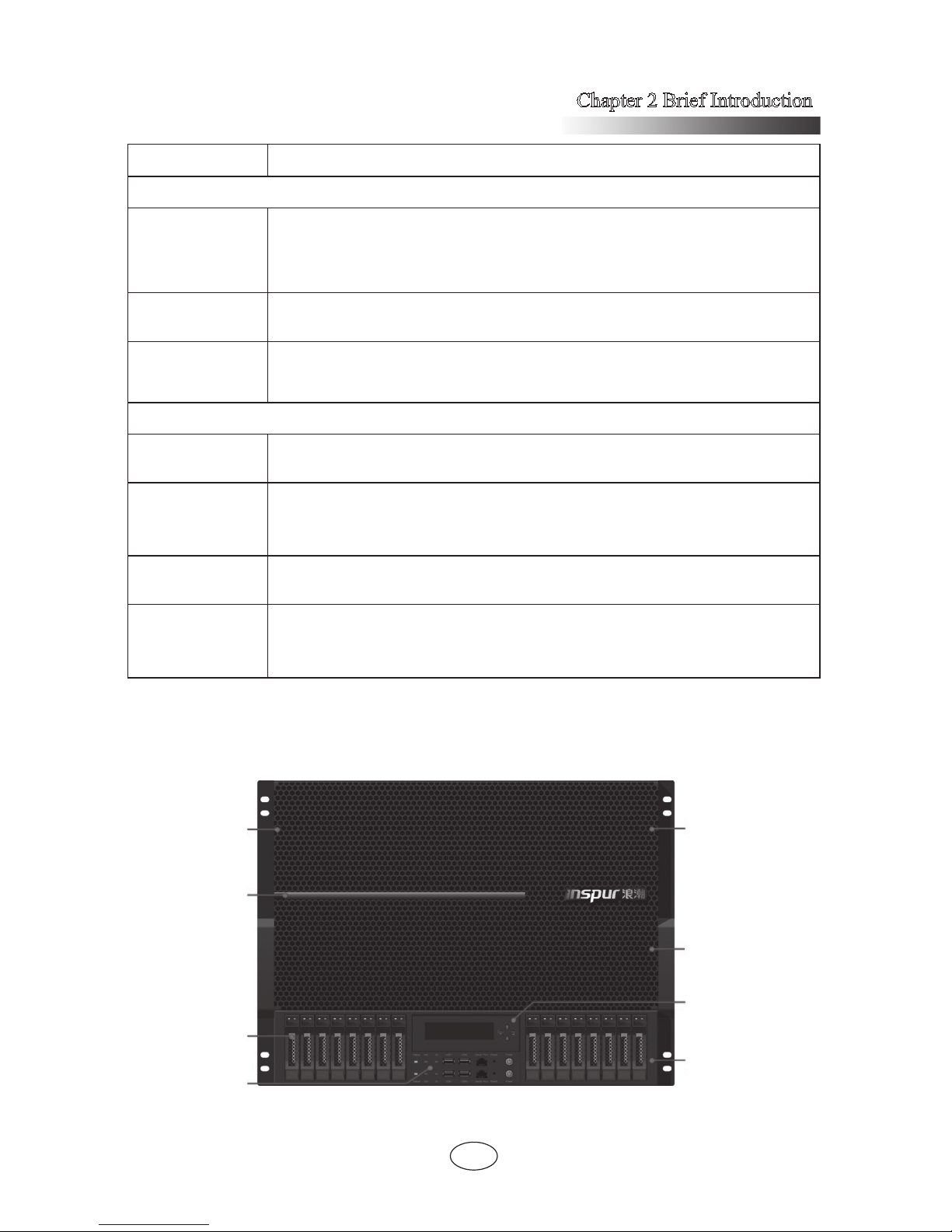
Front view
Chassis Panel
Light bar
HDD Bay
Front Control
Board
Computing Module2
Computing Module1
OLED
Storage Control
Module
Chapter 2 Brief Introduction
12
Name Description
Chassis panel Installed in front of the computing module for dustproof
Indicator light
To indicate the start process through the change of light length when
starting the system;
To indicate the system pressure through the change of light color in
the process of system operation.
Please refer to Indicator Light Description.
HDD bay
16*2.5-inch hot-plug HDDs can be installed with the sequence from
left to right.
In dual partition mode: hard drives ID0 ~ ID7 serve computing
module 2 (upper nodes) and ID8 ~ ID15 serve computing
module 1 (lower node)
Front control
panel
Power ON/OFF operation and the relevant status indicator display;
The machine integrates the top and bottom front control switches
and indicators serving computing module 2 and computing module
1 correspondingly; Only the front control panel serving computing
module 1 is available in 8-socket mode.
Computing
module 1/2
For installation of processor, memory and system fans;
In dual partition mode: computing module 1 is the lower node
and computing module 2 is the upper node; computing module 1
should be installed on the upper position when it is single 4-socket
mode.
OLED screen
To realize the localized visual monitoring and management of the
system
Storage control
module
For the installation of the HDD, HDD backplane, RAID card, OLED
screen and 2 cooling fans.
Chapter 2 Brief Introduction
13
Indicator Light Description (take single 8-socket as an example)
Starting up process display stage
Green indicator on
the left ashes
Server power-on, BMC has not started.
Blue indicator on the
left ashes
BMC starts and the beam pulse is displayed in accordance with
the BIOS initialization process sent by BMC.
Yellow indicator on
the left ashes
BMC failed to start within 10 minutes
Notes:
1. If BMC does not sent the BIOS initialization process to the indicator light within
10 minutes, then the indicator light skips starting process and directly to the power
dissipation display stage.
2. Once the BMC starts, it will send the BIOS initialization process to the indicator
light:
a. If the BIOS initialization process has completed, the indicator light will
quickly nish the starting process bar to jump to power dissipation display
stage
b. If not, BMC will send the real-time process to indicator light, and indicator
light displays the real-time pulse until the initialization completes and jumps
to power dissipation display stage.
Note:
After BMC upgrades FM, the indicator light will return to “Blue indicator on the left
ashes” status, and wait for 10 minutes, enter the system power dissipation display.
Power dissipation display stage
Green
CPU utilization is lower than 20%
CPU temperature is lower than 50
℃
Blue
CPU utilization is between 20%~60%
CPU temperature is between 50℃~65
℃
Yellow
CPU utilization is between 60%~100%
CPU temperature is higher than 65
℃
Chapter 2 Brief Introduction
14
Note: The light color is modied according to the latest BMC detection data:
1. According to CPU utilization: if operating system has a running agent, then it can
obtain the CPU utilization.
2. According to CPU temperature: indicator lights display according to CPU
temperature if it cannot obtain the CPU utilization.
Dual 4-socket mode: indicator lights are divided into two parts, the left part corresponds
to the lower 4-socket and the right part corresponds to the upper 4-socket. The process
and the power dissipation display are the same as single 8-socket.
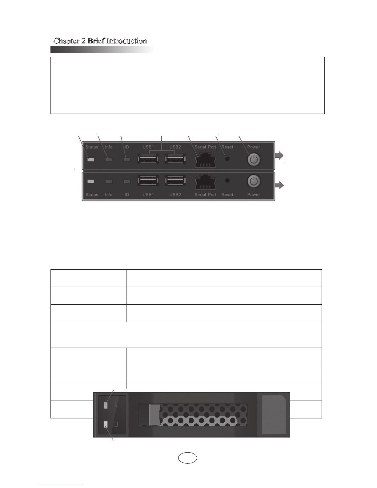
Front control panel view
Name Description
Status indicator
Green indicator on: normal running of the system after startup
Indicator off: the system is not powered up normally
Information indicator Red indicator on: system failure
ID indicator
The indicator is on when conrming the system ID.
It needs the management software to realize this function.
Front USB ports 1,2 Connect USB devices
Serial ports
Connected to the client side through cable, it can monitor the
system and get self-check information.
Reset button
Button for the system reset
The reset operation needs a pointed tool to realize.
Power button
System power on/off button
The button is on with green background after powering up.
HDD bay indicators
Status
indicator
Information
indicator
ID indicator
Front USB
ports1,2
Serial port
Reset
button
Power button
Service for
computing
module2
Service for
computing
module1
HDD locating indicator
HDD status indicator
Chapter 2 Brief Introduction
15
Name Function and description
HDD locating indicator
If a HDD is installed, the indicator ashes in blue when the
HDD is being located.
HDD status indicator
Green indicator on: no read or write activity
Green indicator ash: read or write activity is going on
Red indicator on: HDD failure
Red indicator ash: the HDD is being rebuilt
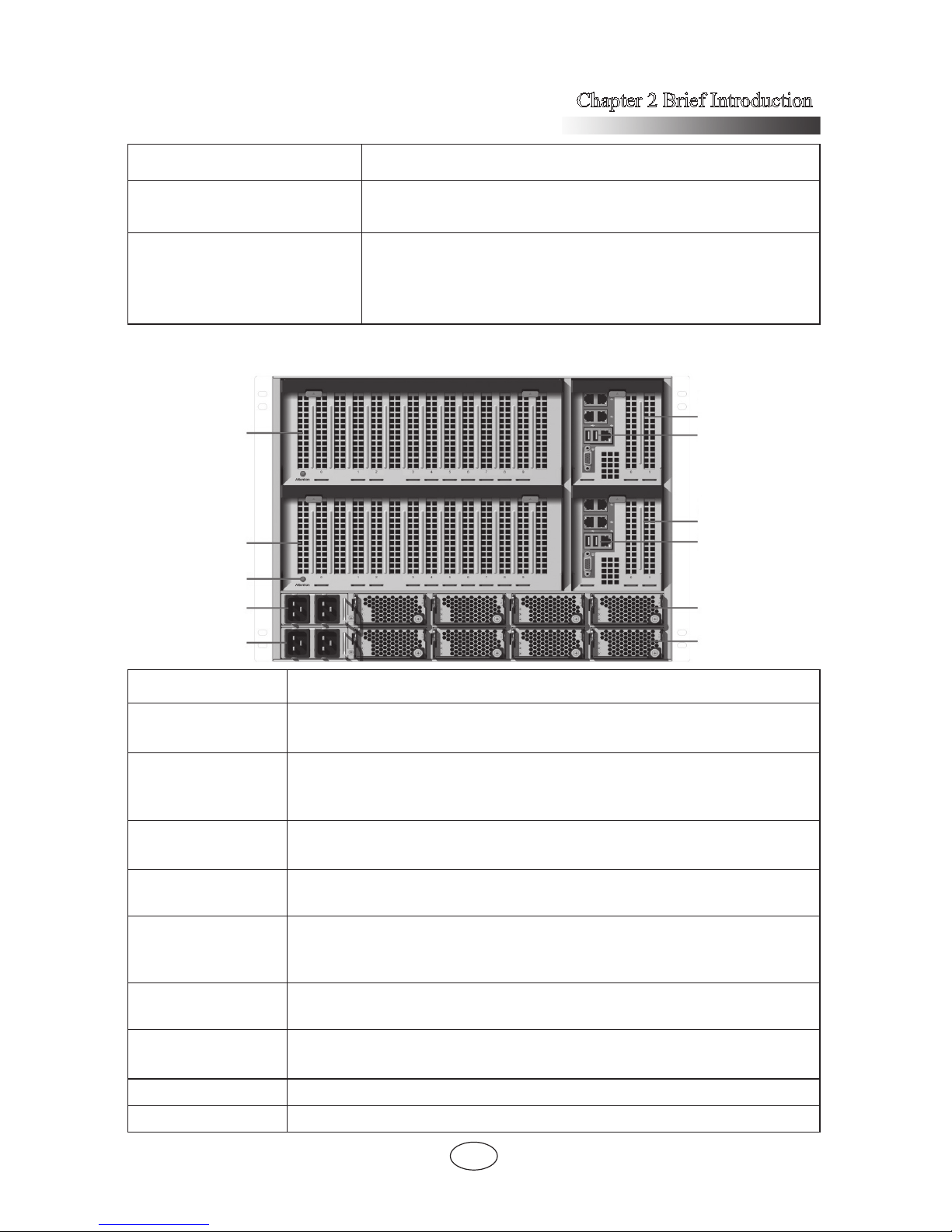
Rear view
Name Function and description
Expansion IO
module
Used for installing expansion card, default conguration is one module;
Each expansion IO module supports 10 PCIE slots.
Basic IO module
Used for installing IO Riser card and other cards, default
conguration is one module, two modules are needed in dual partition
mode. Each basic IO module supports 2 PCIE slots.
IO Riser
Integrated network card, VGA, USB, BMC management interface;
support BMC management card and MSATA.
IO Riser (optional)
When the system is dual partition, this conguration is needed to
serve computing module 2.
Trigger button
Reserved function button. Once function realized, press the button,
indicator light will put out a few seconds later. Expansion IO module
can be pulled out in the system power-on state.
PDU0
PSU 0~3 power distribution board;
Each power input interface supports 2 PSUs.
PDU1
PSU 4~7 power distribution board;
Each power input interface supports 2 PSUs
PSU0-3 Power supply unit 0~3
PSU4-7 Power supply unit 4~7
Expansion
IO module2
PSU0-3
PSU4-7
Expansion
IO module1
Trigger
button
PDU0
PDU1
Basic IO
Module2
IO Riser
(optional)
Basic IO
Module1
IO Riser
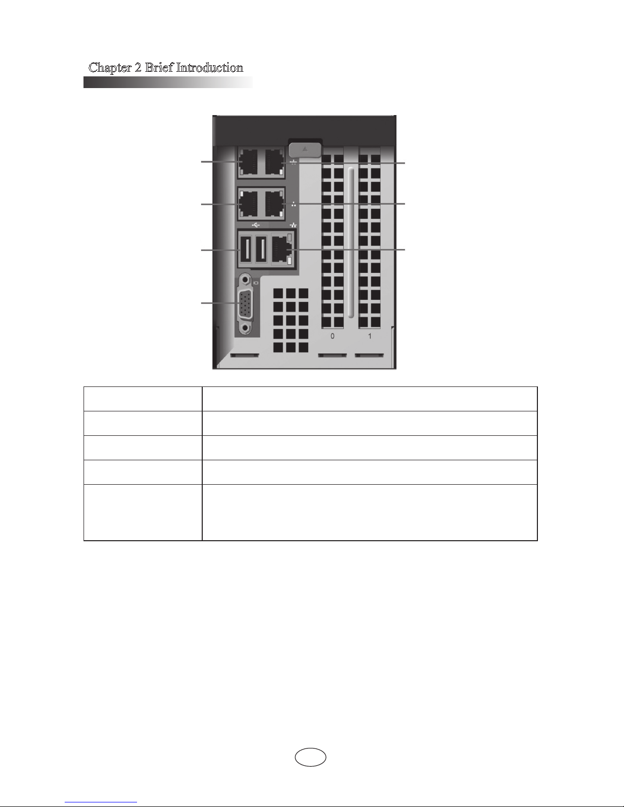
Chapter 2 Brief Introduction
16
IO Riser port
Name Function and description
Network port 0/1/2/3 Each IO Riser integrates 4 Gigabit network ports.
USB port 1/2 Connect USB devices.
VGA port Connect display equipment with standard VGA port.
Management port
Independent RJ45 Gigabit management interface
The system monitoring and management can be realized by the
integrated BMC.
Note: the amount of I/O interface in the above table is under the condition of
conguring one IO Riser.
Start the server
1. First correctly connect the monitor, keyboard and mouse. Then connect all
PDUs configured with this server to the effective power strip or outlet by using the
attached power cable.
2. Press the switch button on the front panel of the server, the fan will run and
system start to power up and self-test.
3. The server will boot from the rst device set in BIOS starting-up management.
Network port0
Network port2
USB port
VGA port
Network port1
Network port3
Management port

Chapter 2 Brief Introduction
17
If the device is unavailable, it will continue to boot the rest corresponding device.
Note:
According to the congured memory capacity, it will take 4 minutes or longer
for the display connected to the server to have display.
Close the server
1. Closing down the server can be achieved through the operation under the
operating system.
2. Closing down the server can be achieved through manually pressing the switch
button on the front panel.
Note: after the above two ways, although the server stops running, some voltage
is still in a usable state, and the system can be started through remote management; to
achieve complete shut down, you need to disconnect the system’s AC power (unplugging
the power line or turning off power strip)
 Loading...