

Inspur SA5212M4 User Manual

© Copyright Inspur 2016. All rights reserved.
No part of this document may be reproduced or transmitted in any form or by any means
without prior written consent of Inspur.
The information in this manual is subject to change without notice.
Inspur is the registered trademark of Inspur. All the other trademarks or registered
trademarks mentioned in this manual are the property of their respective holders.
Edition: 1
Sep 2016

Abstract
This manual contains technical information such as specifications, hardware
operations, software configuration, fault diagnosis, etc. that are relevant to the
maintenance and operation of this server.
It is recommended that server installation, configuration, and maintenance is
performed by experienced technicians only.
Target Audience
This manual is intended for:
●
Technical support engineers
●
Product maintenance engineers
●
Technicians
Warnings:
This manual introduces the server’s technical features, system installation and
setup, which will help the user to understand how best to utilize the server and all its
functionalities.
1.For your safety, please do not disassemble the server’s components arbitrarily.
Please do not extend conguration or connect other peripheral devices arbitrarily. If
needed, please contact Inspur for our support and guidance.
2.Before disassembling the server’s components, please be sure to disconnect all
the power cords connected to the server.
3.BIOS and BMC setup is a signicant factor in correctly conguring your server. If
there are no special requirements, it is suggested to use the default values and not
alter the parameter settings arbitrarily.
4.Please use the driver shipped with the server or provided in Inspur ofcial website,
if you use non-Inspur driver, it may cause compatibility issues and affect the normal
use of the product, Inspur will not assume any responsibility or liability.
The manufacturer is not responsible for any damages, including loss of prots,
loss of information, interruption of business, personal injury, and/or any damage or
consequential damage without limitation, incurred before, during, or after the use of
our products.

Table of Content
1 Safety Instructions ...........................................................................................................1
2 Product Specication Introduction ...................................................................................6
2.1 Introduction ...................................................................................................................6
2.2 Features and Specication ...........................................................................................6
3 Component Identication .................................................................................................9
3.1 3.5×12 Disk Position ....................................................................................................9
3.2 Hard Drive Bay LEDs ...................................................................................................9
3.3 Rear Panel ....................................................................................................................10
3.4 System Board Components ..........................................................................................11
3.5 System Board Jumper Introduction ..............................................................................13
4 Operations .......................................................................................................................14
4.1 Power up the Server .....................................................................................................14
4.2 Power down the Server ................................................................................................14
4.3 Extend the Server from the Rack ..................................................................................14
4.4 Remove the Access Panel ...........................................................................................15
4.5 Install the Access Panel ...............................................................................................16
4.6 Remove the Air Bafe ...................................................................................................16
5 Setup ...............................................................................................................................18
5.1 Optimum Environment ..................................................................................................18
5.2 Rack Warnings .............................................................................................................21
5.3 Identifying the Contents of the Server Shipping Carton ................................................21
5.4 Installing Hardware Options .........................................................................................22
5.5 Installing the Server into the Rack ................................................................................22
5.6 Installing the Operating System ....................................................................................23

6 Hardware Options Installation .........................................................................................24
6.1Processor Option ...........................................................................................................24
6.2 Memory Options ...........................................................................................................26
6.3 Hot-plug Hard Drive Option ..........................................................................................27
6.4 Removing a Hot-plug Hard Drive ..................................................................................28
6.5 Redundant Hot-plug Power Supply Option ...................................................................29
6.6 PCIE Expansion Card Replacement ............................................................................30
6.7 Air Bafe Replacement .................................................................................................30
7 Cabling ............................................................................................................................31
8 BIOS Setup ......................................................................................................................32
8.1 System BIOS Setup Methods .......................................................................................32
8.2 BIOS Conguration .......................................................................................................33
8.3Firmware Update ...........................................................................................................67
9 BMC Settings ..................................................................................................................71
9.1 Introduction ...................................................................................................................71
9.2 Functional Modules ......................................................................................................72
9.3 Web Interface Introduction ...........................................................................................73
9.4 Remote Control ............................................................................................................76
9.5 Power Supply and Heat Radiation ................................................................................78
9.6 BMC Conguration .......................................................................................................79
9.7 Logs ..............................................................................................................................82
9.8 Fault Diagnosis .............................................................................................................83
9.9 System Maintenance ....................................................................................................84
9.10 Command Line Function Introduction .........................................................................85
9.11 Time Zone Table ........................................................................................................90
10 Common Faults, Diagnosis and Troubleshooting ..........................................................92
10.1 Common Faults ..........................................................................................................92
10.2 Diagnosis and Troubleshooting Instructions ...............................................................93

11 Battery Replacement .....................................................................................................96
12 Regulatory Compliance Notices ....................................................................................97
12.1 Regulatory Compliance Identication Numbers .........................................................97
12.2 Federal Communications Commission Notice ............................................................97
12.3 Cables ........................................................................................................................98
12.4 European Union Regulatory Notice ............................................................................98
12.5 Disposal of Waste Equipment by Users in the European Union .................................98
12.6 Korean Notice .............................................................................................................99
12.7 Chinese Notice ...........................................................................................................99
12.8 Battery Replacement Notice .......................................................................................99
13 Electrostatic Discharge ..................................................................................................101
13.1 Preventing Electrostatic Discharge .............................................................................101
13.2 Grounding Methods to Prevent Electrostatic Discharge .............................................101
14 Inspur Support Guide ....................................................................................................102

1 Safety Instructions
Warning: Please be advised to follow the instructions below for safety. Failure to do
so could result to potential dangers that may cause property loss, personal injury or
death.
1. The power supplies in the system may produce high voltages and energy
hazards that may cause personal injury. For your safety, please do not attempt
to remove the cover of the system to remove or replace any component without
assistance provided by Inspur. Only service technicians trained by Inspur are
authorized to remove the cover of the host, and to remove and replace internal
components.
2. Please connect the equipment to the appropriate power supply. Use only power
supplies with the correct voltage and electrical specications according to the
Safety Introduction
label. To protect your equipment from damages caused by a momentary spike
or plunge of the voltage, please use relevant voltage stabilizing equipment, or
uninterruptible power supplies.
3. If you must use an extension cable, please use a three-core cable with properly
grounded plugs. Observe extension cable ratings. Ensure that the total rating of
all equipment plugged into the extension cable does not exceed 80 percent of
the ratings limit for the extension cable.
4. Please be sure to use the power supply components that come with the server,
such as power lines, power socket (if provided with the server) etc. For your
safety, please do not replace power cables or plugs randomly.
5. To prevent electric shock dangers caused by leakage in the system, please
make sure that the power cables of the system and peripheral equipment are
correctly connected to the earthed/grounded power socket. Please connect
the three-core power line plug to the three-core AC power socket that is well
earthed and easy to access. Be sure to use earthing /grounding pin of power
lines and do not use the patch plug or the earthing/grounding pin unplugged
with cables. In the case that the earthing/grounding conductors are not installed
and it is uncertain whether there are appropriate earthing/grounding protections,
1

please do not use or attempt to operate the equipment. Contact and consult an
electrician.
6. Please do not push any objects into the openings of the system. Doing so may
cause re or electric shock.
7. Please place the system far away from the cooling plate and heat sources, and
be sure not to block the air vents.
8. Please be sure not to scatter food or liquid in the system or on other
components, and do not use the product in humid or dusty environments.
9. Using an incompatible battery may cause explosion. When battery replacement
is required, please consult the manufacturer rst, and choose batteries of the
same or equivalent type. Do not disassemble, crush, puncture the batteries or
make the external connection point short circuit, and do not expose them in
the environment over 60°C. Never throw batteries into re or water. Please do
not attempt to open or repair the batteries. Dispose of used batteries according
to instructions. For battery recycling, please contact the local waste recycling
center.
10. Before installing equipment into the rack, please install all front and side
stabilizers on the independent rack rst. Please install the front stabilizers rst, if
connecting with other racks. Please install stabilizers before installing equipment
into the rack. Failure to install the corresponding stabilizers before installing
equipment into the rack may cause the cabinet to tip over, possibly resulting to
severe injury. After installing the equipment and other components into the rack,
only one component can be pulled out from the rack through its sliding part at
one time. Pulling out several components at the same time may cause the rack
to turn over, resulting to serious personal injury.
11. A minimum of two people are required to safely move a rack. The racks
are extremely awkward and heavy, moving them without adequate, trained
personnel could result in severe injury or death.
12. It is prohibited to directly short-circuit the copper busbar. Please do not touch the
copper busbar when the rack is powered on.
13. This is Class A product, and may cause radio interference. In such case, users
may need to take necessary measures to mitigate the interference.
2

Safety Introduction
14. The equipment is intended for installation in a Restricted Access Location.
Note: The following considerations may help avoid the occurrence of problems that
could damage the components or cause data loss, etc.
1. In the event of the following, please unplug the power line plug from the power
socket and contact Inspur’s customer service department:
1) The power cables, extension cables or power plugs are damaged.
2) The products get wet.
3) The products have fallen or have been damaged.
4) Other objects have fallen into the products.
5) The products do not or are unable to function normally even when attempting to
operate according to the instructions.
2. If the system becomes wet or damp, please follow these steps:
1) Power off the equipment, disconnect them with the power socket, wait for 10 to
20 seconds, and then open the host cover.
2) Move the equipment to a well-ventilated place to dry the system at least for 24
hours and make sure that the system is fully dried.
3) Close the host cover, reconnect the system to the power socket, and then power
on.
4) In case of operation failure or other abnormal situations, please contact Inspur
and get technical support.
3. Pay attention to the position of system cables and power cables-avoid placing
wires in high foot trafc locations. Please do not place objects on the cables.
4. Before removing the host cover, and/or touching the internal components,
please allow for the equipment to cool rst. To avoid damaging the mainboard,
please power off the system and wait for ve seconds, and then remove the
components from the mainboard and/or disconnect the peripheral device from
the system. Please remember that only service technicians trained by Inspur are
authorized to remove the cover of the host, and to remove and replace internal
components.
5. If there is modem, telecom or LAN options installed in the equipment, please
pay attention to the followings:
3

1) In the case of thunder and lightning, please do not connect or use the modem.
2) Never connect or use the modem in a damp environment.
3) Never insert the modem or telephone cables into the socket of network interface
controller (NIC).
4) Before unpacking the product package, installing internal components, touching
uninsulated cables or jacks of the modem, please disconnect the modem
cables.
6. In order to prevent electrostatic discharge from damaging the electronic
components in the equipment, please pay attention to the followings:
1) Please remove any static electricity on your body before dismounting or
touching any electronic component in the equipment, to prevent the static
electricity from conducting itself to the sensitive components. You may remove
the static electricity on the body by touching the metal earthing objects (such as
the unpainted metal surface on the rack).
2) Please do not take electrostatic sensitive components that are not ready to be
installed for application out of the antistatic package materials.
3) While working, please touch the earthing conductor or the unpainted metal
surface on the cabinet regularly to remove any static electricity from the body
that may damage the internal components.
7. Upon receiving the proper authorization from Inspur and dismounting the
internal components, please pay attention to the following:
1) Switch the system power supply off and disconnect the cables, including all
connections of the system. When disconnecting the cables, please hold the
connector of the cables and slowly pull the plugs out. Never pull on the cables.
2) The products need to completely cool down before dismounting the host cover
or touching the internal components.
3) During the dismounting process, avoid making large movement ranges to
prevent damage to the components or scratching arms.
4) Handle components and plug-in cards with care. Please do not touch the
components or connection points on the plug-in cards. When handling the
plug-in cards or components, firmly grab the edges of the plug-in cards and
components, and/or their metal xed supports.
8. During the process of rack installation and application, please pay attention to
4

Safety Introduction
the followings:
1) After the rack installation is finished, please ensure that the stabilizers have
been xed to the rack and supported to ground, and the weight of the rack is
rm on ground.
2) Always load from the bottom up, and load the heaviest items rst.
3) When pulling out the components from the rack, apply slight force to keep the
rack balanced.
4) When pressing down the release latch and the rail of components is sliding,
please be careful; as the sliding may hurt your ngers.
5) Do not overload the AC power supply branch circuits in the rack. The total load
of the rack should not exceed 80% of the ratings of the branch circuits.
6) Ensure that components in the rack have good ventilation conditions.
7) When repairing components in the rack, never step on any other components.
5
2 Product Specication Introduction
2.1 Introduction
This type is a kind of server product developed independently. It adopts Intel
Grantley-EP platform, and uses Wellsburg chip set. It supports two mainstream
Intel Xeon E5-26** V4(or E5-26** V3) series processors. It supports 16 DIMM
DDR4 memory, reaching up to 2400MHz. It supports ECC Registered and multiple
senior memory redundancy function.It supports up to 2.5” x 16 SAS/SATA/SSD hot-
plugging hard disks or 3.5” x 12 SAS/SATA/SSD hot-plugging hard disks.
Mainboard integrates
network advanced features. Mainboard integrates BMC/KVM chips. 5 PCI-Express
expansion slots available.Supports SAS 3.0 (12Gb/s) or SAS Raid cards, and
implements exible SAS/SAS RAID solutions. Modular design on components such
as structure, storage, PCI expansion, power supply and fan etc. Energy-saving
and noise reduction design, equipped with PMbus power supply of high efciency,
supports DPNM function, and implements energy saving and consumption reducing.
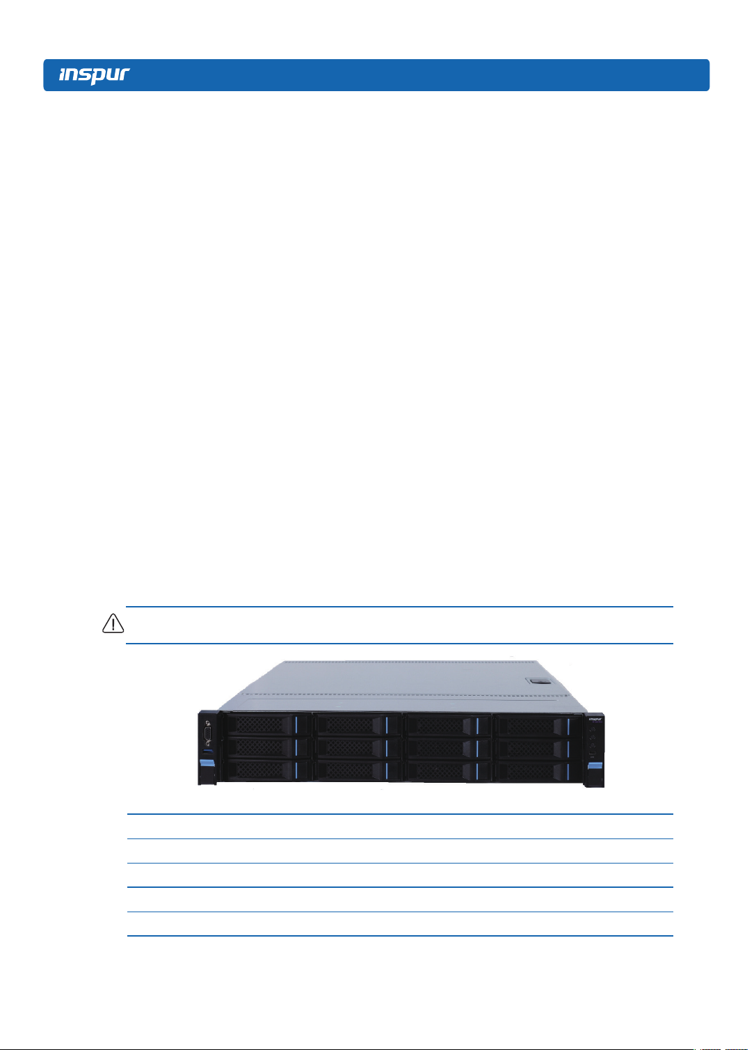
Supports 12 front set 3.5/2.5 inches SAS/SATA/SSD hard disks, and appearances of
them are as shown in the following gure.
Note: The 3.5 inches hard disk bracket could be used to hold a 3.5/2.5 inches hard disk.
Gigabit
network cards of high performance, and supports
2.2 Features and Specication
Processor
Processor Type Intel dual-way Xeon E5-26** V4(or E5-26** V3) Series (supports up to two 145W)
Interface Two Socket-R3 slots.
Chipset
Chipset Type PCH C610(Wellsburg)
6

Product Specication Introduction
Memory
Memory Type DDR4 ECC RDIMM/LRDIMM memory
Single Inline
Memory Module
Qty.
Memory Volume It supports up to 1024GB (64GB for single)
I/O Interface
USB Interface 2 rear set USB 3.0 interfaces, and 2 built-in USB 3.0 interfaces
16
Display Interface
Serial Interface 1 built-in serial port
ID Indicator
Interface
Display Controller
Controller Type A speed 2400 integrated in chip, with max. resolution supporting 1280*1024
SAS Backplane
SAS3.0 backplane It supports hog-plugging SAS/SATA/SSD hard disks.
Network Card
Network Card
Controller
Management Chip
Management Chip
1 front set VGA interface
1 rear set VGA interface
1 ID indicator (blue) and its press button
The mainboard optionally integrates 1 Intel I350 double gigabit or four gigabit
net card, and provides two or four 1000M self-adapting RJ45 net ports;
The mainboard optionally integrates 1 Intel 82599 single-port or double-port
10 gigabit net card, and provides one or two 10 gigabit SFP+Net Card(s).
It integrates 1 independent 1000Mbps network interface, which is used in
IPMI remote management.
Mainboard:
1 onboard PCI Express 3.0 x24 slot (used to support PCI-E Riser, which
could not adapt to external cards); 3 vertically inserted PCIE slots;
PCI Extension Slot
Hard Disk
Hard Drive Type
When there’s one single CPU is in the system:
It could support 1 PCIE x8+x1 slot (able to support network sub card of
management function).
It could support 1 PCIE x8 (in x16 Slots).
When there’re double CPUs in the system:
It could support 1 vertically inserted PCIE x8+x1 slot (able to support
management function network card).
It could support 1 vertically inserted PCIE x8 (in x16 Slots)
It could support 1 vertically inserted PCIE x16 (in x16 Slots)
Via installing a Riser card connecting to a full height and half height card, it could
support 1 vertically inserted PCIE x8 (in x8 Slots) and 1 PCIE x16 (in x16 Slots);
Front set 2.5/3.5 inch SAS, SATA and SSD hard disks; Up to 4 rear set SATA and
SSD hard disks could be supported. (Subject to actual type you purchased)
7
External Storage Driver
CD Driver External USB CD drive.
Drive U Disk Optional drive U disk.
Power Supply
Output power of sing/Double power 550W/800W and above; 1+1
Specification
Power Input Please refer to power input on nameplate tag of the host.
Physical Specification
redundancy; 2 power modules; it supports PMBus power supply, and
implements Node Manager 3.0 function.
External Dimension
of Package
Host Size 447 width × 87 height × 720 depth (unit: mm)
Product Weight
Environment Parameters
Working
Environment
Temperature
Storage &
Transportation
Temperature
Working Humidity 35% -80% relative humidity
Storage &
Transportation
Humidity
651 width × 307 height × 971 depth (unit: mm)
Standard configuration (3 hard disks)
Host weight: 19.5kg;
Gross weight: 32kg. (Gross weight includes: Host + Packing Box + Rail +
Parts Kit)
Full configuration (24 hard disks)
Host weight: 25.8kg;
Gross weight: 35.55kg. (Gross weight includes: Host + Packing box + Rail +
Parts box)
10℃ -35℃
-40℃ -60℃
20% -93% (40℃ ) relative humidity
8
3 Component Identication
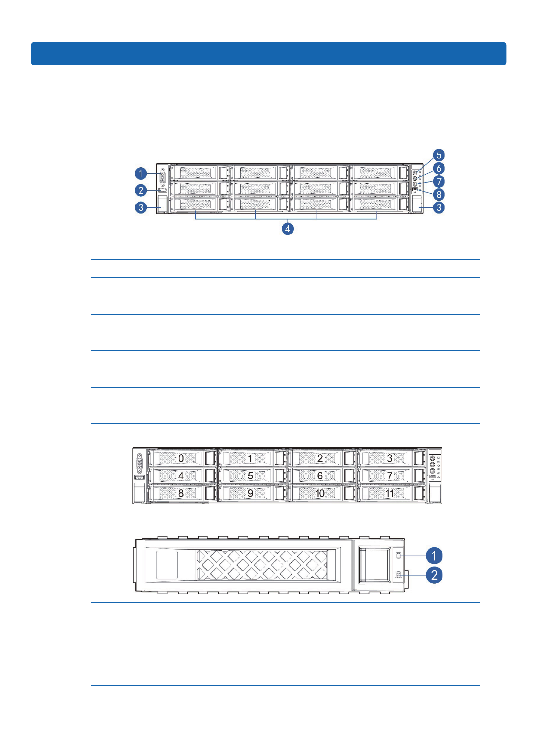
3.1 3.5×12 Disk Position
Number Module Name
1 Front set VGA interface
2 Front set USB 3.0 interface
3 Securing buckle of server and cabinet
4 Front set hard disk slot
Component Identication
5 Server switch button
6 ID light and button
7 System fault indicator button
8 LCD liquid crystal management module interface
3.5×12 disk position hard disk sequence diagram
3.2 Hard Drive Bay LEDs
Number Module Name Description
1 Hard disk activity status indicator
2 Hard disk fault alarming indicator
Constant green: Normal
Flashing green: Hard disk is reading and writing
Constant red: Hard disk fault
Constant blue: Hard disk positioning
Constant pink: In coordination with RAID rebuilding
9
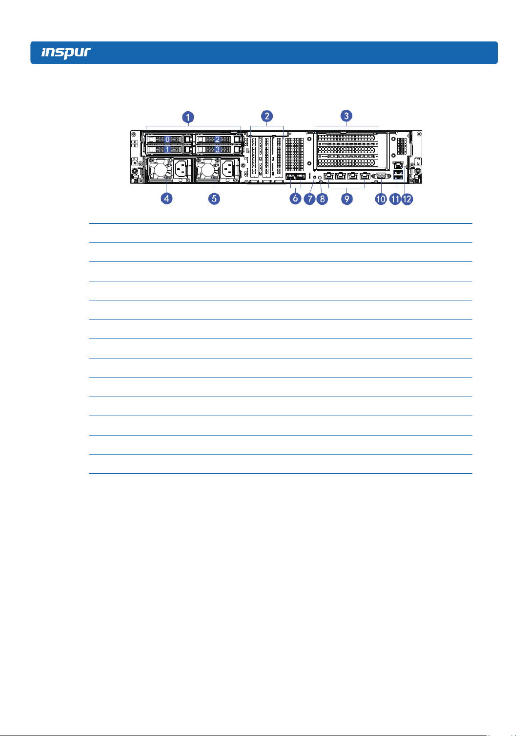
3.3 Rear Panel
Number Module Name
1 Rear set 2.5 inch hard disk slot
2 PCIE slot (half height)
3 PCIE slot (full height)
4 Power supply 0
5 Power supply 1
6 10 Gigabit net card interface
7 BMC reset button
8 ID light and button
9 Gigabit net card interface
10 VGA interface
11 USB3.0 interface
12 IPMI management interface
10
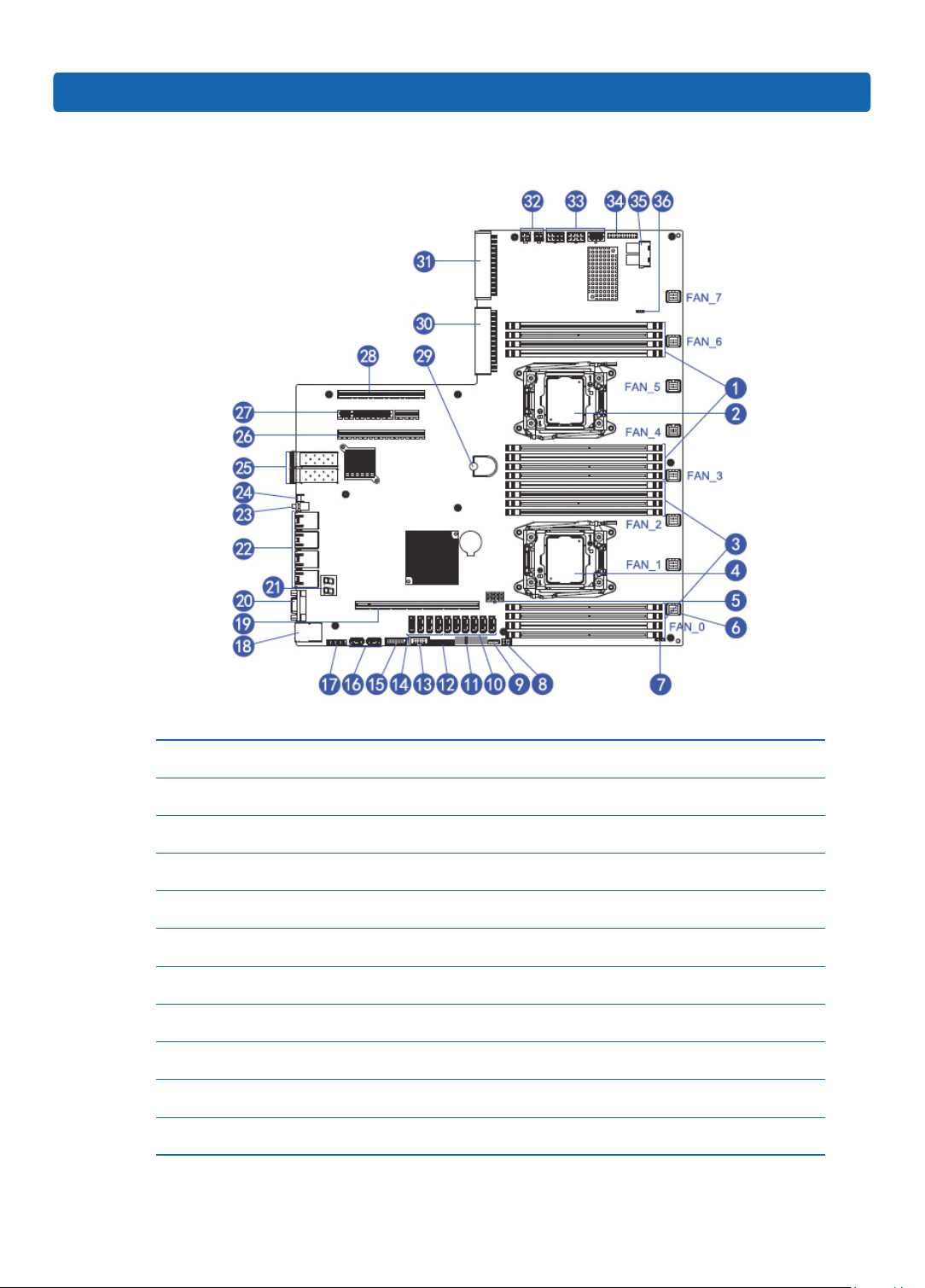
3.4 System Board Components
Component Identication
Number Module Name
1 Memory slot (corresponding with CPU0)
2 CPU0
3 Memory slot (corresponding with CPU1)
4 CPU1
5 GPU Power supply interface
6 System fan interfaces (8 interfaces in all)
7 I2C interface
8 GPIO interface
9 IPMB interface
10 SATA interfaces (6)
11

Number Module Name
11 CLEAR CMOS jumper
12 TCM interface
13 COM interface
14 sSATA interfaces (4)
15 Front set USB 3.0 interface
16 Built-in USB 3.0 interface
17 Front set VGA interface
18 IPMI management interface / rear set USB 3.0 interface (2)
19 PCIEx24 slots (corresponding with CPU1)
20 Rear set VGA interface
21 Debug light
22 Gigabit network port
23 ID light and button
24 BMC Reset button
25 10 Gigabit net port
26 PCIEx16 slots (corresponding with CPU1)
27 PCIEx8 (corresponding with CPU0)
28 PCIEx8 (in x16 slots corresponding with CPU0)
29 Mainboard handle
30 PSU1
31 PSU0
32 Power interface (4 port)
33 Power interface (8 port)
34 Front control panel interface
35 LSI 3008 HDminiSAS interface
36 LSI 3008 SAS Key
12
3.5 System Board Jumper Introduction
See [2.5 Mainboard Layout] for jumper positions.
Clear CMOS Jumper Introduction
Jumper No. Function Description Jumper Functions
Component Identication
CLR_CMOS CMOS clear jumper
Short-circuit pin1-2, to restore normal status; shortcircuit pin2-3, to clear CMOS.
Note:
It is required to shut down the system, as well as disconnect power supply during
CMOS cleaning, and hold for 5 seconds after short-circuiting Pin2-3; then short-
circuit Pin1 and Pin2 of CLR_CMOS jumper with a jumper cap (the default status), to
restore its original status.
13

4 Operations
4.1 Power up the Server
Insert the power cord plug, then press the Power On button.
4.2 Power down the Server
WARNING: To reduce the risk of personal injury, electric shock, or damage to the
equipment, remove the power cord to remove power from the server. The front panel
Power On button does not completely shut off system power. Portions of the power
supply and some internal circuitry remain active until AC power is removed.
IMPORTANT: If installing a hot-plug device, it is not necessary to power down the
server.
1. Back up the server data.
2. Shut down the operating system.
3. Disconnect the power cords.
The system is now without power.
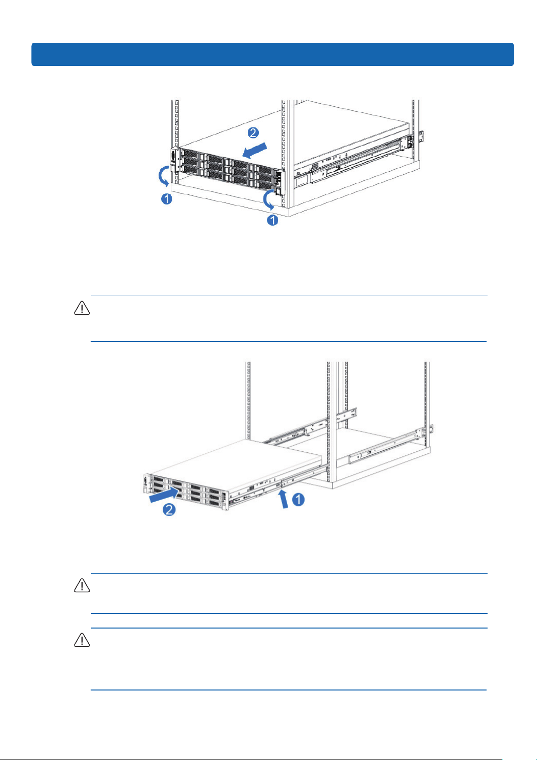
4.3 Extend the Server from the Rack
1. Pull down the quick release levers on each side of the server.
2. Extend the server from the rack.
WARNING: To reduce the risk of personal injury or equipment damage, be sure that
the rack is adequately stabilized before extending a component from the rack.
14
Operations
3. After performing the installation or maintenance procedure, slide the server back
into the rack, and then press the server rmly into the rack to secure it in place.
WARNING: To reduce the risk of personal injury, be careful when sliding the server
into the rack. The sliding rails could pinch your ngers.
4.4 Remove the Access Panel
WARNING: To reduce the risk of personal injury from hot surfaces, allow the drives
and the internal system components to cool before touching them.
CAUTION: For proper cooling do not operate the server without the access panel,
air bafe, or fan installed. If the server supports hot-plug components, minimize the
amount of time the access panel is open.
15

To remove the component:
1. Power down the server if performing a non-hot-plug installation or maintenance
procedure.
2. Extend the server from the rack.
3. Use the screwdriver to loosen the security screw on the hood latch.
4. Lift up on the hood latch handle, and then remove the access panel.
4.5 Install the Access Panel
1. Place the access panel on top of the server with the hood latch open. Allow the
panel to extend past the rear of the server.
2. Push down on the hood latch. The access panel slides to a closed position.
3. Use the screwdriver to tighten the security screw on the hood latch.
4.6 Remove the Air Bafe
CAUTION: For proper cooling do not operate the server without the access panel,
air bafe, or fan installed. If the server supports hot-plug components, minimize the
amount of time the access panel is open.
1. Power down the server.
16
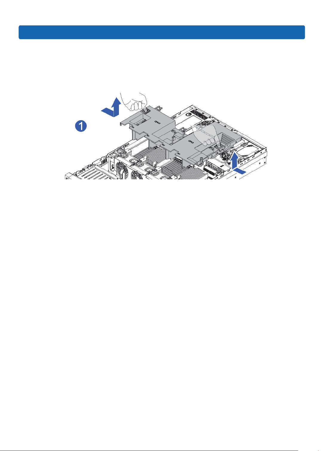
2. Extend or remove the server from the rack.
3. Remove the access panel.
4. Remove the air bafe.
Operations
17
5 Setup
5.1 Optimum Environment
When installing the server in a rack, select a location that meets the environmental
standards described in this section.
5.1.1 Space and Airow Requirements
To allow for servicing and adequate airow, observe the following space and airow
requirements when deciding where to install a rack:
• Leave a minimum clearance of 63.5 cm (25 in) in front of the rack.
• Leave a minimum clearance of 76.2 cm (30 in) behind the rack.
• Leave a minimum clearance of 121.9 cm (48 in) from the back of the rack to the
back of another rack or row of racks.
Inspur Servers draw in cool air through the front door and expel warm air through the
rear door. Therefore, the front and rear rack doors must be adequately ventilated to
allow ambient room air to enter the cabinet, and the rear door must be adequately
ventilated to allow the warm air to escape from the cabinet.
CAUTION: To prevent improper cooling and damage to the equipment, do not block
the ventilation openings.
When vertical space in the rack is not lled by a server or rack component, the gaps
between the components cause changes in airow through the rack and across the
servers. Cover all gaps with blanking panels to maintain proper airow.
CAUTION: Always use blanking panels to ll empty vertical spaces in the rack. This
arrangement ensures proper airow. Using a rack without blanking panels results in
improper cooling that can lead to thermal damage.
18
CAUTION: If a third-party rack is used, observe the following additional requirements
to ensure adequate airow and to prevent damage to the equipment:
• Front and rear doors—If the 42U rack includes closing front and rear doors, you
must allow 5,350 sq cm (830 sq in) of holes evenly distributed from top to bottom
to permit adequate airow (equivalent to the required 64 percent open area for
ventilation).
• Side—The clearance between the installed rack component and the side panels of
the rack must be a minimum of 7 cm (2.75 in).
5.1.2 Temperature Requirements
To ensure continued safe and reliable equipment operation, install or position the
system in a well-ventilated, climate-controlled environment.
The maximum recommended ambient operating temperature (TMRA) for most server
Setup
products is 35°C (95°F). The temperature in the room where the rack is located must
not exceed 35°C (95°F).
CAUTION: To reduce the risk of damage to the equipment when installing third-
party options:
• Do not permit optional equipment to impede airow around the server or to increase
the internal rack temperature beyond the maximum allowable limits.
• Do not exceed the manufacturer’s TMRA.
5.1.3 Power Requirements
Installation of this equipment must comply with local and regional electrical
regulations governing the installation of information technology equipment by
licensed electricians. This equipment is designed to operate in installations covered
by NFPA 70, 1999 Edition (National Electric Code) and NFPA-75, 1992 (code for
Protection of Electronic Computer/Data Processing Equipment). For electrical
power ratings on options, refer to the product rating label or the user documentation
supplied with that option.
19
WARNING: To reduce the risk of personal injury, re, or damage to the equipment,
do not overload the AC supply branch circuit that provides power to the rack. Consult
the electrical authority having jurisdiction over wiring and installation requirements of
your facility.
CAUTION: Protect the server from power uctuations and temporary interruptions
with a regulating uninterruptible power supply (UPS). This device protects the
hardware from damage caused by power surges and voltage spikes and keeps the
system in operation during a power failure.
When installing more than one server, you may need to use additional power
distribution devices to safely provide power to all devices. Observe the following
guidelines:
● Balance the server power load between available AC supply branch circuits.
● Do not allow the overall system AC current load to exceed 80 percent of the branch
circuit AC current rating.
● Do not use common power outlet strips for this equipment.
● Provide a separate electrical circuit for the server.
5.1.4 Electrical Grounding Requirements
The server must be grounded properly for optimal operation and safety. In the United
States, you must install the equipment in accordance with NFPA 70, 1999 Edition
(National Electric Code), Article 250, as well as any local and regional building
codes.
In Canada, you must install the equipment in accordance with Canadian Standards
Association, CSA C22.1, and Canadian Electrical Code. In all other countries, you
must install the equipment in accordance with any regional or national electrical
wiring codes, such as the International Electrotechnical Commission (IEC) Code
364, parts 1 through 7. Furthermore, you must be sure that all power distribution
devices used in the installation, such as branch wiring and receptacles, are listed or
20
certied grounding-type devices.
Because of the high ground-leakage currents associated with multiple servers
connected to the same power source, Inspur recommends the use of a PDU that is
either permanently wired to the building’s branch circuit or includes a nondetachable
cord that is wired to an industrial-style plug. NEMA locking-style plugs or those
complying with IEC 60309 are considered suitable for this purpose. Using common
power outlet strips for the server is not recommended.
5.2 Rack Warnings
WARNING: To reduce the risk of personal injury or damage to the equipment,
please be sure of the following:
• The leveling jacks are extended to the oor.
Setup
• The full weight of the rack rests on the leveling jacks.
• The stabilizing feet are attached to the rack if it is a single-rack installation.
• The racks are coupled together in multiple-rack installations.
• Only one component is extended at a time. A rack may become unstable if more
than one component is extended for any reason.
WARNING: To reduce the risk of personal injury or equipment damage when
unloading a rack:
• At least two people are needed to safely unload the rack from the pallet. An empty
42U rack can weigh as much as 115 kg (253 lb), can stand more than 2.1 m (7 ft)
tall, and may become unstable when being moved on its casters.
• Never stand in front of the rack when it is rolling down the ramp from the pallet.
Always handle the rack from both sides.
5.3 Identifying the Contents of the Server Shipping Carton
Unpack the server shipping carton and locate the materials and documentation
necessary for installing the server. All the rack mounting hardware necessary for
installing the server into the rack is included with the rack or the server.
21
The contents of the server shipping carton include:
● Server
● Power cord
● Power cord clasp
● Hardware documentation, Documentation CD, and software products
● Rack-mounting hardware
In addition to the supplied items, you may need:
● Operating system or application software
● Hardware options
5.4 Installing Hardware Options
Install any hardware options before initializing the server. For options installation
information, refer to the option documentation. For server-specic information, refer
to “Hardware options installation.”
5.5 Installing the Server into the Rack
CAUTION: Always plan the rack installation so that the heaviest item is on the
bottom of the rack. Install the heaviest item rst, and continue to populate the rack
from the bottom to the top.
1. Install the server into the rack. For more information, see the installation
instructions included with the Slide Rail System.
2. Connect peripheral devices to the server. For connector identication information,
see Rear panel components in this guide.
WARNING: To reduce the risk of electric shock, re, or damage to the equipment,
do not plug telephone or telecommunications connectors into RJ-45 connectors.
3. Connect the power cord to the rear of the server.
IMPORTANT: When using cable management arm components, be sure to leave
enough slack in each of the cables to prevent damage to the cables when the server
22
is extended from the rack.
4. Connect the power cord to the AC power source.
WARNING: To reduce the risk of electric shock or damage to the equipment:
• Do not disable the power cord grounding plug. The grounding plug is an important
safety feature.
• Plug the power cord into a grounded (earthed) electrical outlet that is easily
accessible at all times.
• Unplug the power cord from the power supply to disconnect power to the
equipment.
• Do not route the power cord where it can be walked on or pinched by items placed
against it. Pay particular attention to the plug, electrical outlet, and the point where
the cord extends from the server.
Setup
5.6 Installing the Operating System
To operate properly, the server must have a supported operating system installed.
For the latest information on supported operating systems, refer to the Inspur
website (http://www.inspur.com/eportal/ui?pageId=444443).
Methods to install an operating system on the server include:
● Ruijie assisted installation—Insert the Ruijie server kit CD into the CD-ROM drive
and reboot the server.
● Manual installation—Insert the operating system CD into the CD-ROM drive and
reboot the server. This process may require you to obtain additional drivers from
the Inspur website
(http://www.inspur.com/eportal/ui?pageId=444443).
23

6 Hardware Options Installation
Introduction
If more than one option is being installed, read the installation instructions for all the
hardware options and identify similar steps to streamline the installation process.
WARNING: To reduce the risk of personal injury from hot surfaces, allow the drives
and the internal system components to cool before touching them.
CAUTION: To prevent damage to electrical components, properly ground the
server before beginning any installation procedure. Improper grounding can cause
electrostatic discharge.
6.1 Processor Option
The server supports single- and dual-processor operation.
CAUTION: To avoid damage to the processor and system board, only authorized
personnel should attempt to replace or install the processor in this server.
CAUTION: To help avoid damage to the processor and system board, do not install
the processor without using the processor installation tool.
CAUTION: To prevent possible server malfunction and damage to the equipment,
multiprocessor congurations must contain processors with the same part number.
To install the component:
1 Power down the server
2 Extend the server from the rack
3 Remove the access panel
4 Remove the air bafe
5 Remove the heatsink
6 Remove the processor:
24

Hardware Options Installation
Step 1: Open the two locking levers and the CPU xing plate.
Step 2: Install CPU into the CPU socket, and then remove the protective cover.
Step 3: Clamp CPU with CPU fixing plate, and then close the two locking levers
rmly.
Step 4: Fix the CPU heatsink above CPU, and then fasten the bolts on the heatsink.
25
 Loading...