

Inspur NX8840 User Manual

Dear users of Inspur server:
Sincerely than you for selection of Inspur server!
This manual introduces the technical characteristics and the system
installation and setup of the server, and helps you to particularly understand
and expediently use this server.
Please deliver the package of our product to the waste recycling station
for recycling, in favor of pollution prevent and benefi t the humankind.
This manual is the property of the Inspur Group Co., Ltd.
This User Manual is not to be copied by any group or person in any
manner without the consent of Inspur Group Co., Ltd. The Inspur Group
Co., Ltd. reserves the right of revise this manual momentarily.
Any alteration about the content of this manual will be noticed.
Please contact Inspur Group Co., Ltd., if you have any questions or
advice about this manual.
Inspur Group Co., Ltd.
1
st
2013
“Inspur” is registered trademark of Inspur Group Co., Ltd.
Other trademarks belong to other corresponding registered companies.

Statement
Please read the following statement before you use this server formally. Only
when you have read this statement hereinafter and agreed the following terms, you can
formally use this server. If you have any questions about the following terms, please
contact our supplier or us directly. If you have no questions about these terms and start
to use this server, it acquiesces that you have agreed the following terms.
1. We must call your attention that you must not alter any other parameters in
the main board BIOS of this server at any time, except for the parameters which we
promote that you can alter.
2. If there are any hardware problems when you use this server, or you wish
to upgrade the hardware, please feed back the detail hardware confi guration of your
computer to our Customer Service. Don’t disassemble the server case or any hardware
components in the case by yourself.
3. In this server, the MEMORY, CPU, CPU Fan and Fan are in given standard.
Please don’t use them with the corresponding components of any other computers
confusedly.
4. When you have any software problems during the application of this server,
we hope that you fi rstly contact the corresponding software supplier and then he will
contact us in favor of communication so as to solve your problem together, especially
the software problems about the database, the installation and running of the network
management software or other networking product.
5. Please firstly read the accompany Brief User Guide, when you install this
server. Please contact our Customer Service Center, if you have any questions about the
application.
6. We must call your attention that in the application process, you should pay
attention to do necessary backup of your fi le.
7. The copyrights of the markers and names of the software and hardware product
referred in this manual are the property of corresponding companies.
8. In the above statement, “us” indicates the Inspur Group Co., Ltd. The Inspur
Group Co., Ltd. holds the right of fi nal explanation about the above statement.

Safety Information
In order to guarantee your personal safety, avoid any risk of damaging system and
usage environment, please make sure to read this part carefully, and execute according
to this strictly, before installing and using this product.
Note: In order to help you use the equipment, the following considerations
can help avoid the occurrence of problems that may damage the components or
cause data loss etc.
1. In case of the following cases, please unplug the power line plug of products
from the power socket and contact customer service department of Inspur:
— The power cables, extended cables or power plugs are damaged.
— The products get wet by water.
— The products have fallen off or been damaged.
— Objects fall into the products.
— When operating according to the operation instructions, the products cannot
function normally.
2. If the system becomes damp, please dispose according to the following steps:
— Switch off the power supplies of the system and the equipment, disconnect
them with the power socket, wait for 10 to 20 minutes, and then open the cover of the
host.
— Move the equipment to the ventilation place to dry the system at least for 24
hours and make sure that the system is fully dried.
— Close the cover of the host, re-connect the system to the power socket, and
then start the equipment.
— In case of operation failure or abnormal situation, please contact Inspur and get
technical support.
3. Pay attention to the position of the system cables and power cables, wire them
in places not to be stepped on or knocked down and ensure not to place other objectives
on the cables.
4. Before dismounting the cover of host or contacting the internal components,
you shall cool down the equipment first; to avoid damaging the main-board, please
power off the system and wait for 5 seconds, and then dismount the components from

the main-board or disconnect the connection of peripheral equipment of the system.
5. If there are modulator-demodulator, telecommunication or local area network
options in the equipment, please pay attention to the following matters:
— In case of thunder and lightning weather, please do not connect or use the
modulator-demodulator. Otherwise, it may be subject to lightning strike.
— Never connect or use modulator-demodulator in moist environment.
— Never insert the modulator-demodulator or telephone cables to the socket of
network interface controller (NIC).
— Before unpacking the product package, contacting or installing internal
components or contacting un-insulated cables or jacks of the modulator-demodulator,
please disconnect the modulator-demodulator cables.
6. In order to prevent the electrostatic discharge from damaging the electronic
components in the equipment, please pay attention to the following matters:
— You shall conduct off the static electricity on the body before dismounting or
contacting any electronic component in the equipment. You can conduct off the static
electricity on the body by contacting the metal earthing objects (such as the unpainted
metal surface on the chassis) to prevent the static electricity on the body from
conducting itself to the sensitive components.
— For electrostatic sensitive components not ready to be installed for application,
please do not take them out from the antistatic package materials.
— During the work, please touch the earthing conductor or the unpainted metal
surface on the cabinet regularly to conduct off the static electricity on the body that
may damage the internal components.
7. When dismounting the internal components with the approval of Inspur, please
pay attention to the following matters:
— Switch off the system power supply and disconnect the cables, including
disconnecting any connection of the system. When disconnecting the cables, please
grab the connector of cables and plug it out, and never pull the cables.
— Before dismounting the cover of cabinet or touching the internal components,
the products need to be cooled down.
— Before dismounting and touching any electronic component in the equipment,
you shall conduct off the static electricity on the body by touching the metal earthing
objectives.

— During the dismounting process, the operation shall not be too big, so as to
prevent damage to the components or scratching of the arms.
— Carefully deal with the components and plug-in cards, and please never touch,
the components or connection points on the plug-in cards. When taking the plug-in
cards or components, you should grab the edges of the plug-in cards or components or
their metal fi xed supports.
8. During the process of cabinet installation and application, please pay attention
to the following matters:
— After the installation of cabinet is fi nished, please ensure that the supporting
feet have been fi xed to the rack and supported to the ground, and all weight of the rack
have been fell onto the ground.
— It shall install into the cabinet according to the sequences from the bottom to
the top, and fi rst install the heaviest component.
— When pulling out the components from the cabinet, it shall apply force slightly
to ensure the cabinet to keep balance and stabilization.
— When pressing down the release latch of the sliding rail of components and
sliding in or out, please be careful, as the sliding rail may hurt your fi gures.
— Never make the AC power branch circuit in the cabinet overload. The sum of
cabinet load shall not exceed 80% of the ratings of branch circuits.
— Ensure that components in the cabinet have good ventilation.
— When repairing components in the cabinet, never step on any other
components.
Warning: the following warnings show that there are potential dangers that
may cause property loss, personal injury or death:
Warning 1: The power supply equipment in the system may generate high voltage
and dangerous electrical energy and thus cause personal injury. Please do not dismount
the cover of the host or to dismount and replace any component in the system by
yourself, unless otherwise informed by Inspur; only maintenance technicians trained
by Inspur have the right to disassemble the cover of the host, dismount and replace the
internal components.
Warning 2: Please connect the equipment to appropriate power supply, and
the power should be supplied by external power supply which is indicated on the
rated input label. To prevent your equipment from damages caused by momentary

spike or plunge of the voltage, please use relevant voltage stabilizing equipment or
uninterruptible power supply equipment.
Warning 3: If extended cables are needed, please use the three-core cables
matched with correct earthed plug, and check the ratings of the extended cables to
make sure that the sum of rated current of all products inserted into the extended cables
do not exceed 80% of the limits of the rated currents of the extended cables.
Warning 4: Please be sure to use the supplied power supply component, such
as power lines, power socket (if supplied with the equipment) etc. For the safety of
equipment and the user, do not replace randomly power cables or plugs.
Warning 5: To prevent electric shock dangers caused by leakage in the system,
please make sure that the power cables of the system and peripheral equipment are
correctly connected to the earthed power socket. Please connect the three-core power
line plug to the three-core AC power socket that is well earthed and easy to access, be
sure to use the earthing pin of power lines and do not use the patch plug or the earthing
pin unplugged with cables. In case of the earthing conductors not installed and it is
uncertain whether there are appropriate earthing protections, please do not operate or
use the equipment. Contact and consult with the electrician.
Warning 6: To avoid short circuit of internal components and fi re or electric shock
hazards, please do not fi ll any object into the open pores of the system.
Warning 7: Please place the system far away from the cooling plate and at the
place with heat sources, and be sure not to block the air vents.
Warning 8: Be sure not to scatter food or liquid in the system or on other
components, and do not use the product in humid and dusty environment.
Warning 9: The replacement of batteries with those of another model may
cause explosion. When replacement of batteries is required, please consult first the
manufacturer and choose batteries of the same or a similar model recommended by the
manufacturer. Do not dismount, extrude and pink the batteries or make the external
connection point short circuit, and do not expose them in the environment over 60°C.
Never throw them into fi re or water. Please do not try to open or repair the batteries,
and be sure to reasonably deal with the fl at batteries and do not put the fl at batteries,
the circuit boards that may include the batteries and other components with other
wastes. For relevant battery recovery, please contact the local waste recovery and
treatment mechanism.

If what you bought is the chassis, besides carefully read the installation
description attached with the cabinet products and get known about the special warning
notices and installation process, you must abide by the following preventive measures
to guarantee the cabinet to be stable and safe:
Warning 10: Before installing equipment in the chassis, please install front
and side supporting feet on the independent chassis; for cabinet connecting with
other chassis, it shall install the front supporting foot first. If you fail to install
correspondingly the supporting foot before installing equipment in the chassis, it may
cause the cabinet to turn over in some cases, and thus may cause personal injury.
Therefore, it is necessary to install supporting feet before installing equipment in the
chassis. After installing the equipment and other components in the chassis, it can only
pull out one component from the cabinet through its sliding component at one time.
Pulling out several components at the same time may lead the cabinet to turn over and
cause serious personal injury.
Warning 11: Please do not move the chassis independently. Considering the height
and weight of the chassis, at least two people are needed to complete its movement.
Warning 12: Declaration
The product is Grade A product, and in the living environment, it may cause
radio interference. In such case, it may need the user to take feasible measures for the
interference.

Regarding the Manual
● Product Description
● System BIOS
● Operating System Installation
● Integrated Raid Systems
● Common Problem and Trouble-shooting
We suggest you read this manual seriously before you use this server for fear the
unnecessary faults in your operation.
Technical Service Tel.: 86-531-88546554
Address: NO.1036 Langchao Road, Jinan, China, Inspur Group Co., Ltd
Post Code: 250101

Content
Chapter One NX8840 Computer Blade Overview ..................................................1
1.1 NX8840 Computer Blade Technical Specifi cation .......................................1
1.2 NX8840 Computer Blade View ....................................................................1
1.3 NX8840 Computer Blade Unit Interface and Indicator Introduction ...........1
1.4 Usage of NX8840 Computer Blade ..............................................................2
1.5 Jumper Setting ...............................................................................................2
Chapter Two System BIOS .......................................................................................5
2.1 How to Enter the BIOS Setup .......................................................................5
2.2 BIOS System Menu Introduction ..................................................................5
Chapter Three Operation System Installation ........................................................18
3.1 Manual Installation of Windows Server 2008 R2 .........................................18
3.2 Manual Installation of Red Hat Enterprise Linux 6.2 ...................................23
Chapter Four Integrated RAID System ...................................................................28
4.1 How to Enter SATA RAID Confi guration Interface ......................................28
4.2 Application of Control Keys .........................................................................28
4.3 SATA RAID Confi guration ...........................................................................28
Chapter Five Common Problems and Troubleshooting .........................................32
5.1 Restart the machine .......................................................................................32
5.2 Failure occurs when starting the machine .....................................................32
5.3 Other notices .................................................................................................35
5.4 Technical support information.......................................................................36

1
Chapter One NX8840 Computer Blade Overview
1.1 NX8840 Computer Blade Technical Specifi cation
Processor
Processor Type 2~4 Intel® XeonSandy Bridge-EP 4600 series processors
Platform
Platform Type Romley-EP 4S Platform(Socket-R
)
Memory
Memory Type DDR3-1600/1333/1066/800 ECC Registered
Memory Slot Qty. 32 (8DIMM/CPU)
Memory Volume Supports maximum 512GB
Display Controller
Controller Type Mainboard integrated display card
Hard Disk Controller
SATA Controller Supports 2 25-inch hot plug SATA, SSD and SAS hard disks.
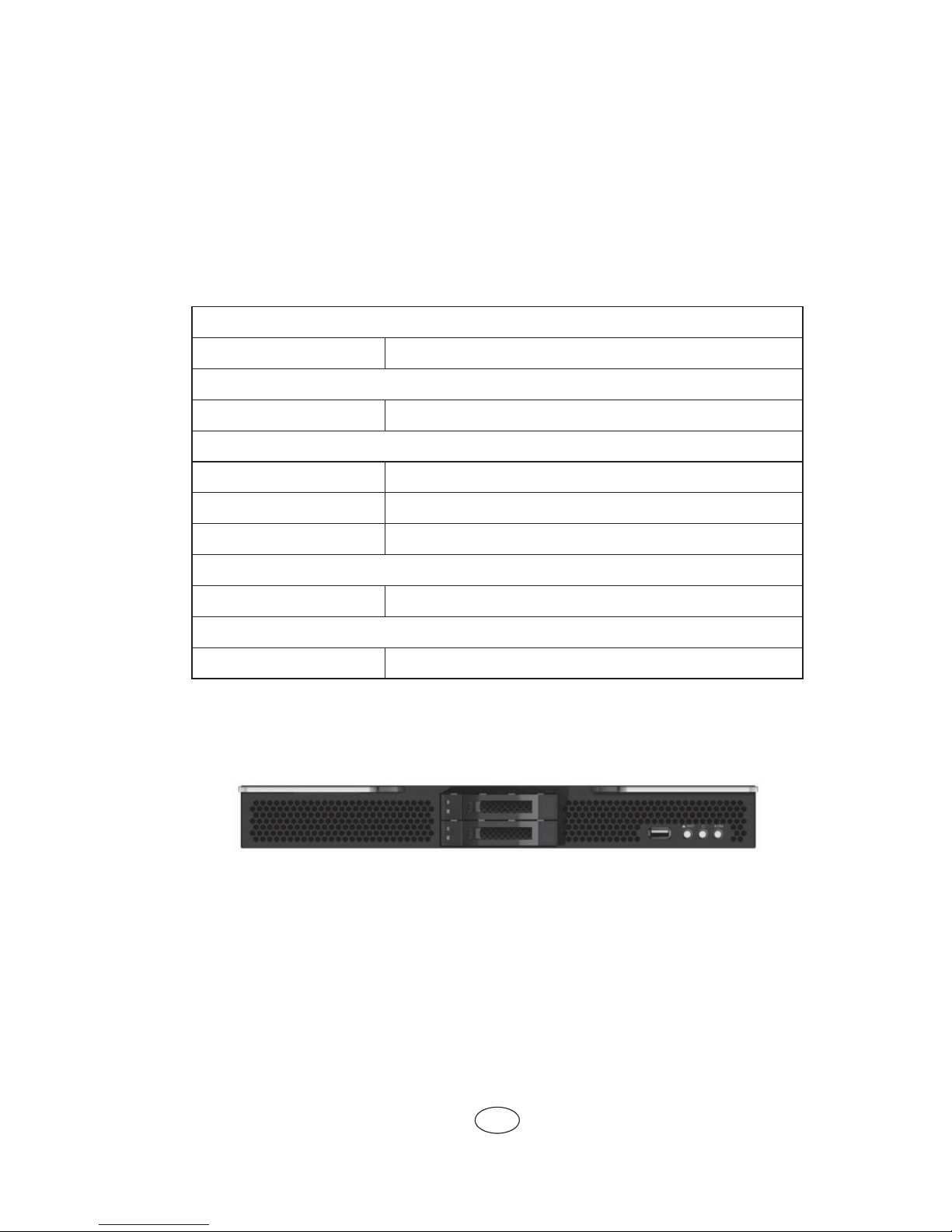
1.2 NX8840 Computer Blade View
Front view of NX8840 computer blade is as shown in the following Figure 1-1:
Figure 1-1 NX8840 Front View
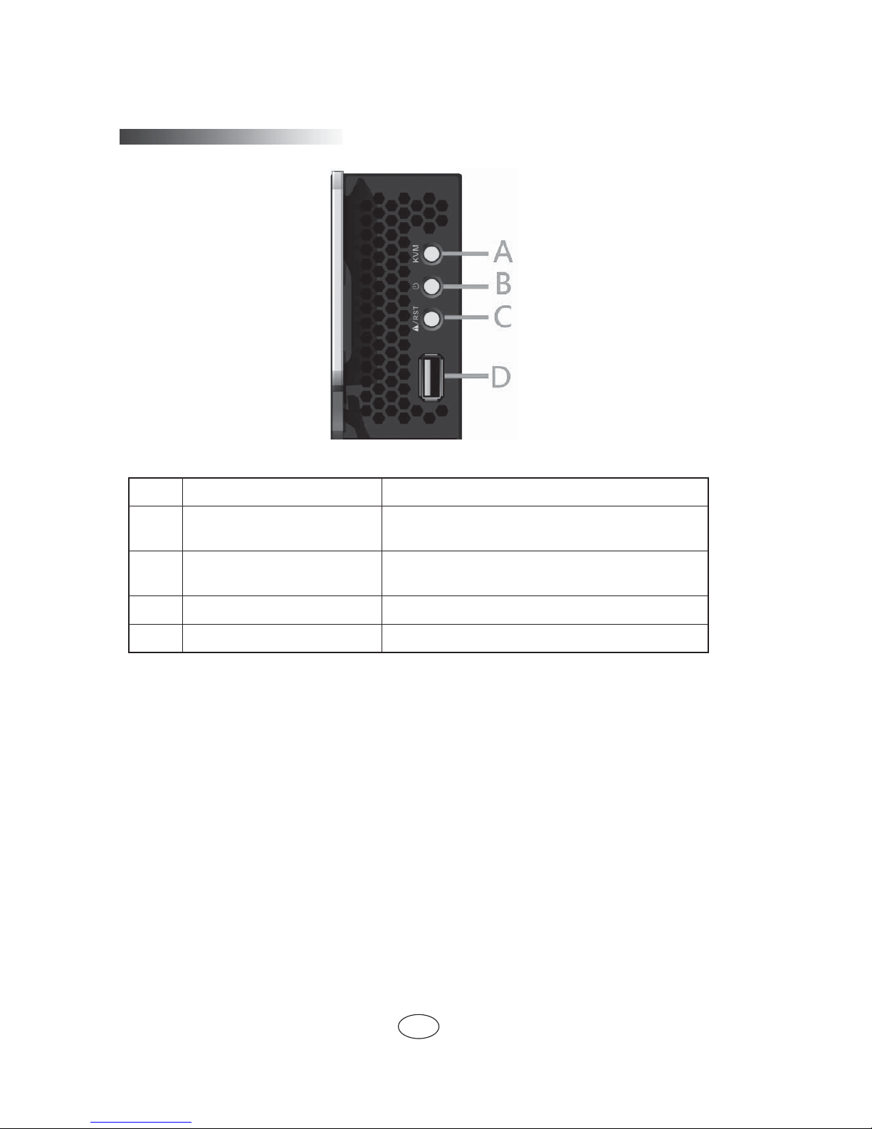
1.3 NX8840 Computer Blade Unit Interface and Indicator Introduction
2
Chapter One NX8840 Computer Blade Overview
Figure 1-2 Blade Unit Interface and Indicator
Number
Name Status/Function
A
Blade KVM Status Indicator/
KVM Button
Lights on when blade KVM is activated, blue/manual
activates current blade module KVM
B Start Button/Power Indicator
Lights on when switch blade module/blade operates
normally and fl ashes when starts BMC, green
C Restart Button/Failure Indicator Lights on when blade module restarts/blade fails, red
D
USB Interface Connects USB devices
1.4 Usage of NX8840 Computer Blade
NX8840 computer blade shall use with Inspur I800 server, and computer blade
could only be used when installed in I8000 server system, about how to install NX8840
blade onto an I8000 server, please refer to related parts in I8000 server use manual or
illustration on chassis of I8000 blade server host, which is not repeated here.
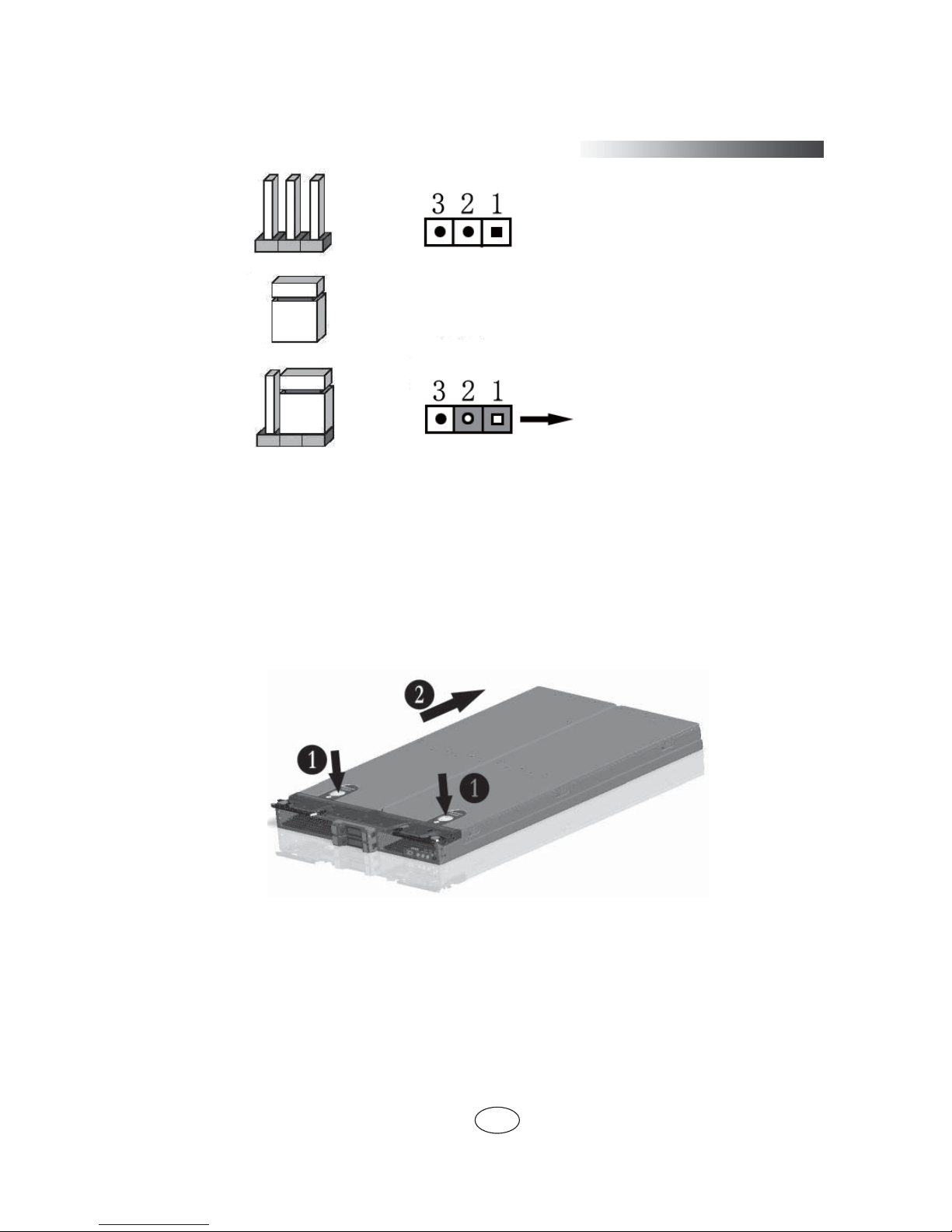
1.5 Jumper Setting
Mainboard jumper setting is an operation to short circuit two pins of the jumper to
change interface functions, according to the following fi gure, so as to adjust mainboard
functions.
3
Chapter One NX8840 Computer Blade Overview
Figure 1-3 Jumper Setting Illustration
Open upper panel of the chassis
To modify mainboard jumper, please open upper panel of the chassis, under
authorization of Inspur Group Co., Ltd. Opening methods are as follows:
1. Shut down the system, pull out blade module, and press unlock spring;
2. Push outwards according to directions shown by arrows, remove upper cover of
the chassis.
Figure 1-4 Open Chassis Upper Cover Illustration
Clear CMOS Jumper Introduction
pin
jumper cap
setting Select 1-2 pin(s) for
short circuit
4
Chapter One NX8840 Computer Blade Overview
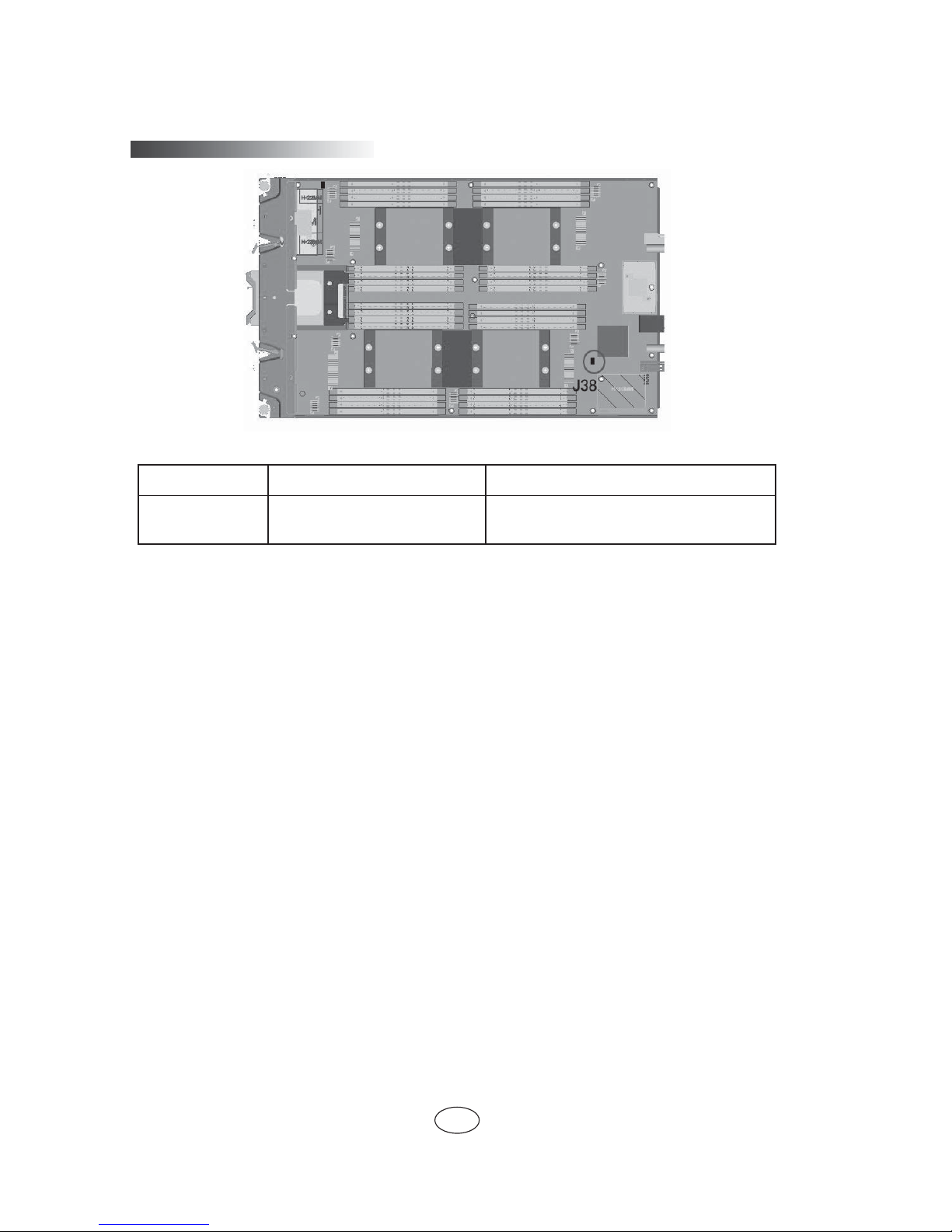
Figure 1-5 Jumper Position Illustration
Jumper No. Function Description Jumper Functions
J38 CMOS clear jumper
Short circuit of Pin1-2, normal status;
short circuit Pin2-3, clear CMOS.
Note:
It is required to maintain 5 seconds when short circuit Pin2-3 during clearing
CMOS; then short circuit Pin1 and Pin2 of CLR_CMOS jumper again using jumper
cap (default setting status), to restore to original status.
 Loading...