

Inspur NX5460M4 User Manual

Dear users of Inspur server,
Sincerely thank you for using Inspur server.
This manual introduces the technical characteristics, system installation and setup of the
server, and helps you to particularly understand and expediently use this server.
Please deliver the package of our product to the waste recycling station, in favor of pollution
prevention and beneting humankind.
This manual is the property of Inspur.
This User Manual is not to be copied by any group or person in any manner without the
consent of Inspur. Inspur reserves the right of revising this manual momentarily.
The information in this manual is subject to change without notice.
Please contact Inspur, if you have any questions or advice about this manual.
Inspur
December, 2015
is the registered trademark of Inspur. All the other trademarks or
registered trademarks mentioned in this manual are the property of their respective holders.

Copyright Introduction
Document Version: V1.0
Release Date: 5th December. 2015
Document Introduction: 1st formal issuance
Abstract
The manual introduces issues closely related to maintenance such as specications, hardware
operation, software conguration, service terms, fault diagnosis etc. of the server.
Readers of this guide will be deemed to have abundant knowledge about the server product
and have received adequate technical training, and will not cause any personal injury or
product damage during operation and maintenance.
Target Audience
This manual mainly applies to the following personnel:
● Technical support engineers
● Product maintenance engineers
It is suggested that server maintenance operation shall be carried out by professional
engineers with related server knowledge via referring to this manual.

Table of Contents
1 Safety Instructions ......................................................................................................... 1
2 Product Overview ..........................................................................................................6
2.1Technical Specications .......................................................................................6
2.2 NX5460M4 Views ..............................................................................................6
2.3 Usage of NX5460M4 Blade Server ....................................................................7
2.4 CLR_CMOS Jumper Introduction .....................................................................8
3 BIOS Setup ....................................................................................................................9
3.1 System BIOS Setup Methods .............................................................................9
3.2 BIOS Settings .....................................................................................................10
3.3 Firmware Update ................................................................................................41
4 RAID System .................................................................................................................43
4.1 How to Enter RAID Conguration Interface ......................................................43
4.2 Control Keys .......................................................................................................44
4.3 SAS RAID Settings ............................................................................................44
4.4 SATA RAID Settings ..........................................................................................47
5 Hardware Maintenance ..................................................................................................50
5.1 Tool Preparation ..................................................................................................50
5.2 Parts Replacement ...............................................................................................50
6 Common Faults, Diagnosis and Troubleshooting ..........................................................53
6.1 Common Faults ...................................................................................................53
6.2 Diagnosis and Troubleshooting Instructions .......................................................54
7 Services ..........................................................................................................................57
7.1 How to Obtain Warranty Service .......................................................................57
7.2 How to Contact Inspur ........................................................................................57
8 Certications & Standards .............................................................................................59
8.1 USA FCC Declaration .......................................................................................59
8.2 CE Declaration of EU .........................................................................................59
8.3 China Environmental Labeling ...........................................................................59

1 Safety Instructions
Warning: the following warnings indicate that there are potential dangers that may cause
property loss, personal injury or death:
1. The power supplies in the system may produce high voltages and energy hazards that
may cause personal injury. Please do not demount the cover of the host to remove or
replace any component in the system by yourself, unless otherwise informed by Inspur;
only service technicians trained by Inspur have the right to demount the cover of the
host, remove and replace the internal components.
2. Please connect the equipment to appropriate power supply, and only the type of external
power supply indicated on the electrical ratings label can be used. To protect your
equipment from damages caused by momentary spike or plunge of the voltage, please
use relevant voltage stabilizing equipment or uninterruptible power supply.
Safety Instructions
3. If you must use an extension cable, use a three-core cable with properly grounded plugs.
Observe extension cable ratings. Ensure that the total rating of all equipment plugged
into the extension cable does not exceed 80 percent of the ratings limit for the extension
cable.
4. Please be sure to use the power supply components that come with the server, such as
power lines, power socket (if provided with the server) etc. For the safety of equipment
and users, do not replace power cables or plugs randomly.
5. To prevent electric shock dangers caused by leakage in the system, please make sure
that the power cables of the system and peripheral equipment are correctly connected
to the earthed power socket. Please connect the three-core power line plug to the three-
core AC power socket that is well earthed and easy to access, be sure to use the earthing
pin of power lines and do not use the patch plug or the earthing pin unplugged with
cables. In case of the earthing conductors not installed and it is uncertain whether there
are appropriate earthing protections, please do not operate or use the equipment. Contact
and consult with the electrician.
6. Please do not push any objects into the openings of the system. Doing so may cause re
or electric shock because of internal components short circuit.
7. Please place the system far away from the cooling plate and the place with heat sources,
1

and be sure not to block the air vents.
8. Be sure not to scatter food or liquid in the system or on other components, and do not
use the product in humid and dusty environment.
9. Using an incompatible battery may cause explosion. When battery replacement is
required, please consult the manufacturer first, and choose batteries of the same or
equivalent type. Do not disassemble, crush, puncture the batteries or make the external
connection point short circuit, and do not expose them in the environment over 60°C.
Never throw them into fire or water. Please do not attempt to open or repair the
batteries, and be sure to reasonably deal with the exhausted batteries and do not put the
exhausted batteries, the circuit boards that may include batteries and other components
together with other wastes. For relevant battery recycling, please contact the local waste
recycling center.
10. Before installing equipment into the rack, please install all front and side stabilizers
on the independent rack rst; for the rack connecting with other racks, it shall install
the front stabilizers first. If you fail to install the corresponding stabilizers before
installing equipment into the rack, it may cause the cabinet to tip over in some cases,
and thus may cause personal injury. Therefore, it is necessary to install stabilizers before
installing equipment into the rack. After installing the equipment and other components
into the rack, it can only pull out one component from the rack through its sliding part
at one time. Pulling out several components at the same time may lead the rack to turn
over and cause serious personal injury.
11. Please do not move the rack by oneself. Considering the height and weight of the rack,
at least two people are needed to complete its movement.
12. Please do not directly touch the copper busbar when the rack is powered on, and it is
prohibited to directly short-circuit the copper busbar.
13. This is Grade A product, and in the living environment, it may cause radio interference.
In such case, users may need to take measures to deal with the interference.
Note: The following considerations can help avoid the occurrence of problems that may
damage the components or cause data loss, etc.
1. In case of the following cases, please unplug the power line plug from the power socket
and contact customer service department of Inspur:
2

Safety Instructions
1) The power cables, extension cables or power plugs are damaged.
2) The products get wet.
3) The products have fallen off or been damaged.
4) Objects fall into the products.
5) When operating according to the operating instructions, the products cannot
function normally.
2. If the system is affected with damp, please dispose according to the following steps:
1) Power off the equipment, disconnect them with the power socket, wait for 10 to 20
seconds, and then open the host cover.
2) Move the equipment to a well-ventilated place to dry the system at least for 24
hours and make sure that the system is fully dried.
3) Close the host cover, reconnect the system to the power socket, and then power on.
4) In case of operation failure or abnormal situation, please contact Inspur and get
technical support.
3. Pay attention to the position of system cables and power cables, wire them in places
not to be stepped on or knocked down and ensure not to place other objectives on the
cables.
4. Before removing the host cover or touching the internal components, you shall cool
down the equipment first; to avoid damaging the mainboard, please power off the
system and wait 5 seconds, and then remove the components from the mainboard or
disconnect a peripheral device from the system.
5. If there are modem, telecom or LAN options installed in the equipment, please pay
attention to the following matters:
1) In case of thunder and lightning weather, please do not connect or use the modem.
Otherwise, it may suffer from lightning stroke.
2) Never connect or use the modem in damp environment.
3) Never insert the modem or telephone cables into the socket of network interface
controller (NIC).
4) Before unpacking the product package, touching or installing internal components
or touching uninsulated cables or jacks of the modem, please disconnect the modem
cables.
6. In order to prevent the electrostatic discharge from damaging the electronic components
in the equipment, please pay attention to the following matters:
3

1) You shall conduct off the static electricity on the body before dismounting or
touching any electronic component in the equipment. You can conduct off the
static electricity on the body by touching the metal earthing objects (such as the
unpainted metal surface on the rack) to prevent the static electricity on the body
from conducting itself to the sensitive components.
2) For electrostatic sensitive components not ready to be installed for application,
please do not take them out from the antistatic package materials.
3) During the work, please touch the earthing conductor or the unpainted metal surface
on the cabinet regularly to conduct off the static electricity on the body that may
damage the internal components.
7. When dismounting the internal components with the approval of Inspur, please pay
attention to the following matters:
1) Switch off the system power supply and disconnect the cables, including all
connections of the system. When disconnecting the cables, please hold the
connector of cables and plug it out, and never pull the cables.
2) Before dismounting the host cover or touching the internal components, the
products need to be cooled down.
3) Before dismounting or touching any electronic component in the equipment, you
shall conduct off the static electricity on the body by touching the metal earthing
objectives.
4) During the dismounting process, the movement range shall not be too big, so as to
prevent damage to the components or scratching arms.
5) Carefully deal with the components and plug-in cards, and please never touch the
components or connection points on the plug-in cards. When taking the plug-in
cards or components, you should grab the edges of the plug-in cards or components
or their metal xed supports.
8. During the process of rack installation and application, please pay attention to the
following matters:
1) After the rack installation is nished, please ensure that the stabilizers have been
xed to the rack and supported to the ground, and all weight of the rack have been
fell onto the ground.
2) Always load from the bottom up, and load the heaviest items rst.
3) When pulling out the components from the rack, it shall apply force slightly to keep
4

Safety Instructions
the rack balanced.
4) When pressing down the release latch of the sliding rail of components and sliding
in or out, please be careful, as the sliding rail may hurt your gures.
5) Do not overload the AC power supply branch circuits in the rack. The total load of
the rack shall not exceed 80% of the ratings of branch circuits.
6) Ensure that components in the rack have good ventilation conditions.
7) When repairing components in the rack, never step on any other components.
5
2 Product Overview
2.1 Technical Specications
Processor
Processor type 1~2 Intel® Xeon Haswell-EP series processors
Platform type Grantley-EP 2S Platform
Memory
Memory type
DIMM slot Qty. 24
Total capacity Support up to 1.5TB
Display controller
Controller type Integrated graphics
Network
Controller type Integrated dual gigabit Ethernet controller
HDD controller
SATA controller Support 2 2.5-inch hot-plug SAS/ SATA / SSD HDDs
DDR4-1600/1866/2133 ECC Registered
Support RDIMM & LRDIMM
RAID
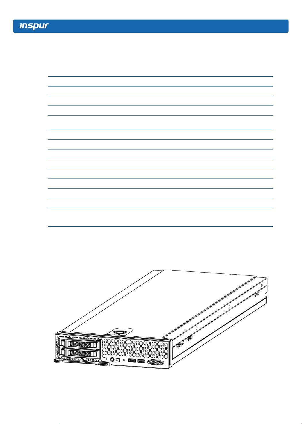
2.2 NX5460M4 Views
General view
● Onboard RAID controller: support RAID0,RAID1
● SAS RAID Mezz: support RAID0,RAID1,RAID5
6
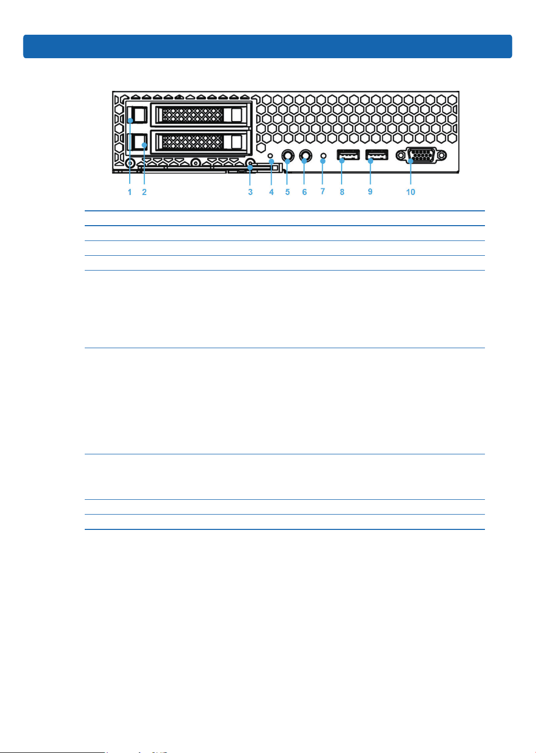
Front view
No. Name & Function
1~2 HDD1/HDD0
3 Handle
4 Reset button
Power button/indicator
Off: the compute node is not powered on;
5
Steady green: the compute node is powered on normally;
Blinking yellow: the power of computer node is in lock state for the moment, or
there is a power problem, it fails to power on.
Product Overview
UID button/indicator:
Used to locate the compute node in the rack;
ON/OFF: controlled through SMC remotely or manual operation.
6
7
8~9 USB3.0 port
10 VGA
Off: BMC initialization is complete or the compute node is not located;
Blinking blue: BMC initializing. The compute node’s BMC detects it has been
inserted and is building communication with SMC;
Steady blue: the compute node is located.
Status indicator
Off: the compute node is normal;
Blinking yellow: there is a critical alarm.
2.3 Usage of NX5460M4 Blade Server
NX5460M4 blade server must be used together with Inspur I9000 server; it can be used
only after being installed in I9000 server system. About how to install NX5460M4 into I9000
server, please refer to the relevant section in I9000 server user manual or the installation
diagram on the host chassis of I9000 blade server, it will not be repeated here.
7

2.4 CLR_CMOS Jumper Introduction
The jumper position is shown in the following gure:
Jumper No. Name Jumper Functions
CLR_CMOS CMOS clear jumper
Note:
It is required to shut down the system, as well as disconnect power supply during
CMOS clearing, and hold for 5 seconds after short-circuiting Pin2-3; then short-circuit Pin1
and Pin2 of CLR_CMOS jumper (the default status) with a jumper cap, to restore to its
original status.
Short-circuit pin1-2, to restore normal status; shortcircuit pin2-3, to clear CMOS.
8

3 BIOS Setup
This chapter introduces how to congure BIOS. All operations described in this section
are only limited to operators or administrators with system maintenance qualication.
BIOS is a basic input and output system. The system parameters and hardware
parameters can be adjusted through special setup procedure. BIOS has a great impact on
the system booting and running, setting parameters improperly may cause conicts among
hardware resources, or degrade the system running performance. Hence understanding the
BIOS setup is signicant to the conguration of your server. If no especial requirement, you
are suggested to use the default value and not alter the parameters arbitrarily.
1. Before changing the BIOS setup, please record the corresponding original setup. Hence
when there are operating problems in the system due to the option altered, the setup can revert to
the previous state.
2. Ordinarily the factory default settings are the optimal settings. Don’t try to alter the
parameters before you understand their denotations.
3. The common settings are introduced in detail in this chapter. The less referred options
during using are simply explained or not.
4. The BIOS content varies according to different congurations of the products; hence the
detailed introduction is elided.
BIOS Setup
3.1 System BIOS Setup Methods
Power on the server, system starts to boot, when Inspur logo appears on the screen,
press [ESC] button; when “Entering Setup...” appears in the lower right corner, it will enter
system BIOS configuration later, and you could select options in BIOS main menu using
arrow buttons to enter sub-menu.
Note: Options in grey are not available. Options with symbol “ ” have a sub-menu.
Control key instruction table
9
Key Function
<Esc> Exit or return from sub-menu to main menu.
<←> or <→> Select a menu.
<↑> or <↓> Move the cursor up or down.
<Home> or <End> Move the cursor to the top or bottom of the screen
<+> or <-> Select the previous or next value or setting of the current one.
<F1> Help
<F2> Restore to the last conguration.
<F9> Restore to default conguration.
<F10> Save and exit
<Enter> Execute commands or select a sub-menu.
3.2 BIOS Settings
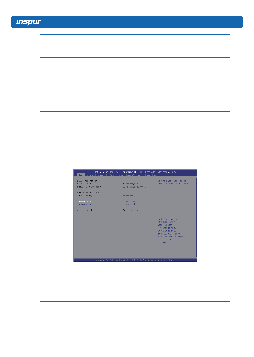
3.2.1 Main Menu
Main interface includes BIOS information, memory information, system date, etc. As
shown below:
Parameter description of Main interface:
Parameters Function description
BIOS Information
Memory Information Display the current total memory
System Date (Day mm/dd/yyyy)
System Time (hh/mm/ss)
Access Level Current access level
10
Display BIOS Vender, Core version, BIOS version, build
date and time
Display and set system date and time
Use <Tab> key to switch between items, you can directly
enter the value or use +/- key to change
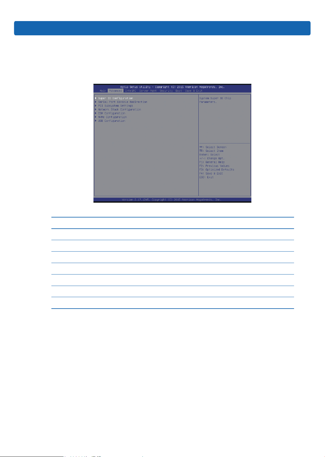
3.2.2 Advanced Menu
Advanced interface includes BIOS system parameters and the related function control,
such as serial port, PCI subsystem, CSM, NVMe, USB, onboard NIC, etc; as shown below.
BIOS Setup
Parameter description of Advanced interface:
Parameters Function description
Super IO Conguration AST2400 I/O chip parameter conguration
Serial Port Console Redirection Serial port console redirection settings
PCI Subsystem Settings PCI subsystem settings
Network Stack Conguration Network stack conguration
CSM Conguration CSM conguration
NVMe Conguration NVMe conguration
USB Conguration USB conguration
3.2.2.1 Super IO Configuration
Super IO Configuration interface is used to set the options related with I/O chip, as
shown below:
11
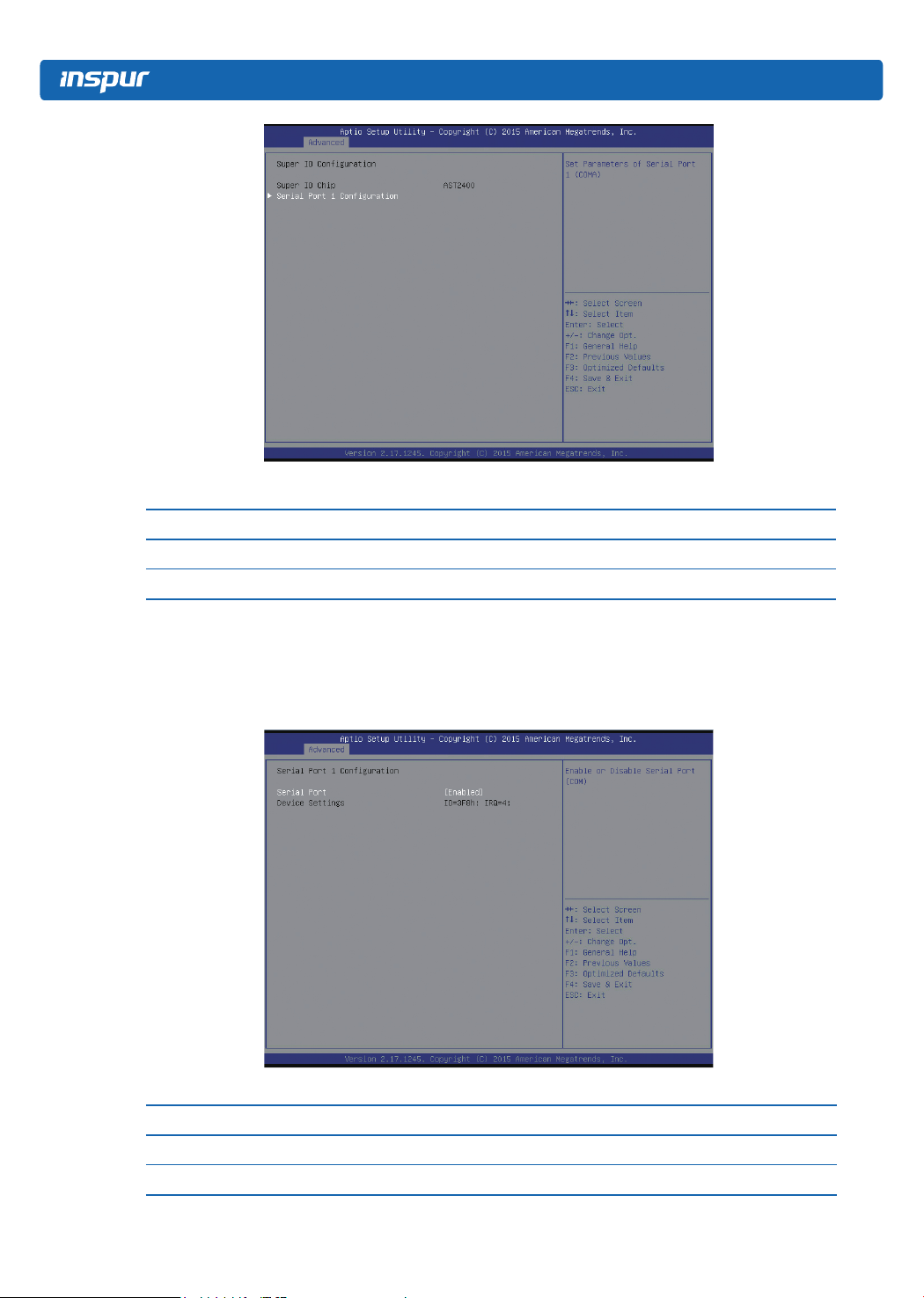
Parameter description of AST2400 Super IO Conguration interface:
Parameters Function description
Super IO Chip Display the super I/O chip used by the motherboard currently
Serial Port1 Conguration Serial port1 conguration
Serial Port1 Conguration
Serial Port1 Conguration interface is used to set the options related with I/O chip, as
shown below:
Parameter description of Serial Port1 Conguration interface:
Parameters Function description
Serial Port On-off control of serial port1
Device Settings IO resources used by serial port1
12
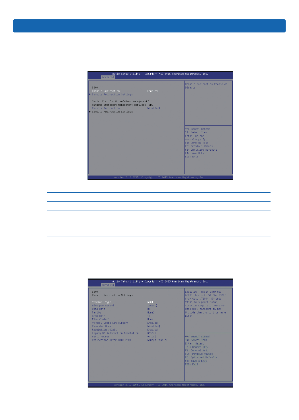
3.2.2.2 Serial Port Console Redirection
Serial Port Console Redirection interface is used to set the options related with serial
port console redirection, as shown below:
Parameter description of Serial Port Console Redirection interface:
Parameters Function description
Console Redirection On-off setting of console redirection
Console Redirection Settings Parameter settings of console redirection
Console Redirection(EMS) On-off setting of console redirection (EMS)
Console Redirection Settings(EMS) Parameter settings of console redirection (EMS)
BIOS Setup
Console Redirection Settings
If the option of Console Redirection is set to 【Enabled】, Console Redirection Settings
menu will be opened, as shown below:
13
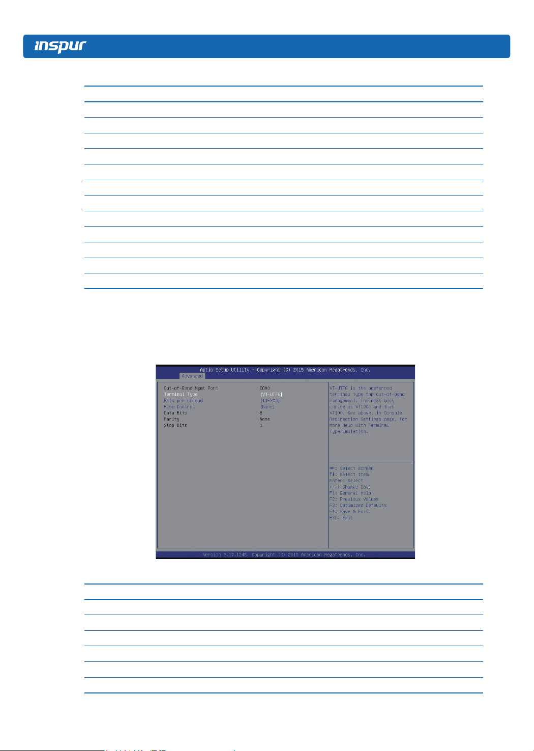
Parameter description of Console Redirection Settings interface:
Parameters Function description
Terminal Type Terminal type setting
Bits per second Bits per second setting
Data Bits Data bits setting
Parity Parity setting
Stop Bits Stop bits setting
Flow Control Flow control setting
VT-UTF8 Combo Key Support VT-UTF88 combo key support setting
Recorder Mode Recorder mode setting
Resolution 100×31 Terminal resolution setting
Legacy OS Redirection Resolution Legacy OS redirection resolution setting
Putty KeyPad Putty keypad setting
Redirection After BIOS POST Redirection setting after BIOS POST
Console Redirection Settings (EMS)
If the option of Console Redirection (EMS) is set to 【Enabled】, Console Redirection
Settings menu will be opened, as shown below:
Parameter description of Console Redirection Settings interface:
Parameters Function description
Terminal Type Terminal type setting
Bits per second Bits per second setting
Flow Control Flow control setting
Data Bits Data bits setting
Parity Parity setting
Stop Bits Stop bits setting
14
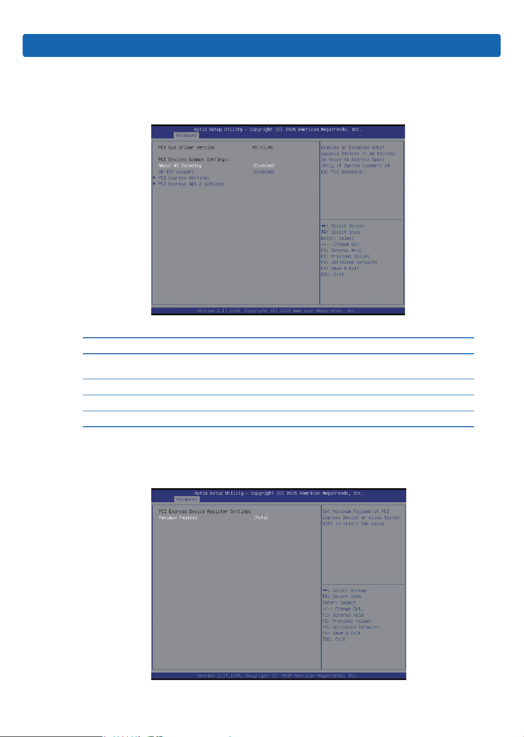
3.2.2.3 PCI Subsystem Settings
PCI Subsystem Settings interface is used to set the options related with PCI subsystem,
as shown below:
Parameter description of PCI Subsystem Settings interface:
Parameters Function description
Above 4G Decoding
SR-IOV Support On-off setting of SR-IOV support
PCI Express Settings PCI express settings
PCI Express GEN 2 Settings PCIe Gen2 settings
Above 4G memory access control switch, enable or disable
above 4G decoding function
BIOS Setup
PCI Express Settings
PCI Express Settings interface is used to set the options related with PCIe subsystem, as
shown below:
15
Parameter description of PCI Express Settings interface:
Parameters Function description
Maximum Payload Maximum Payload setting of PCIe devices
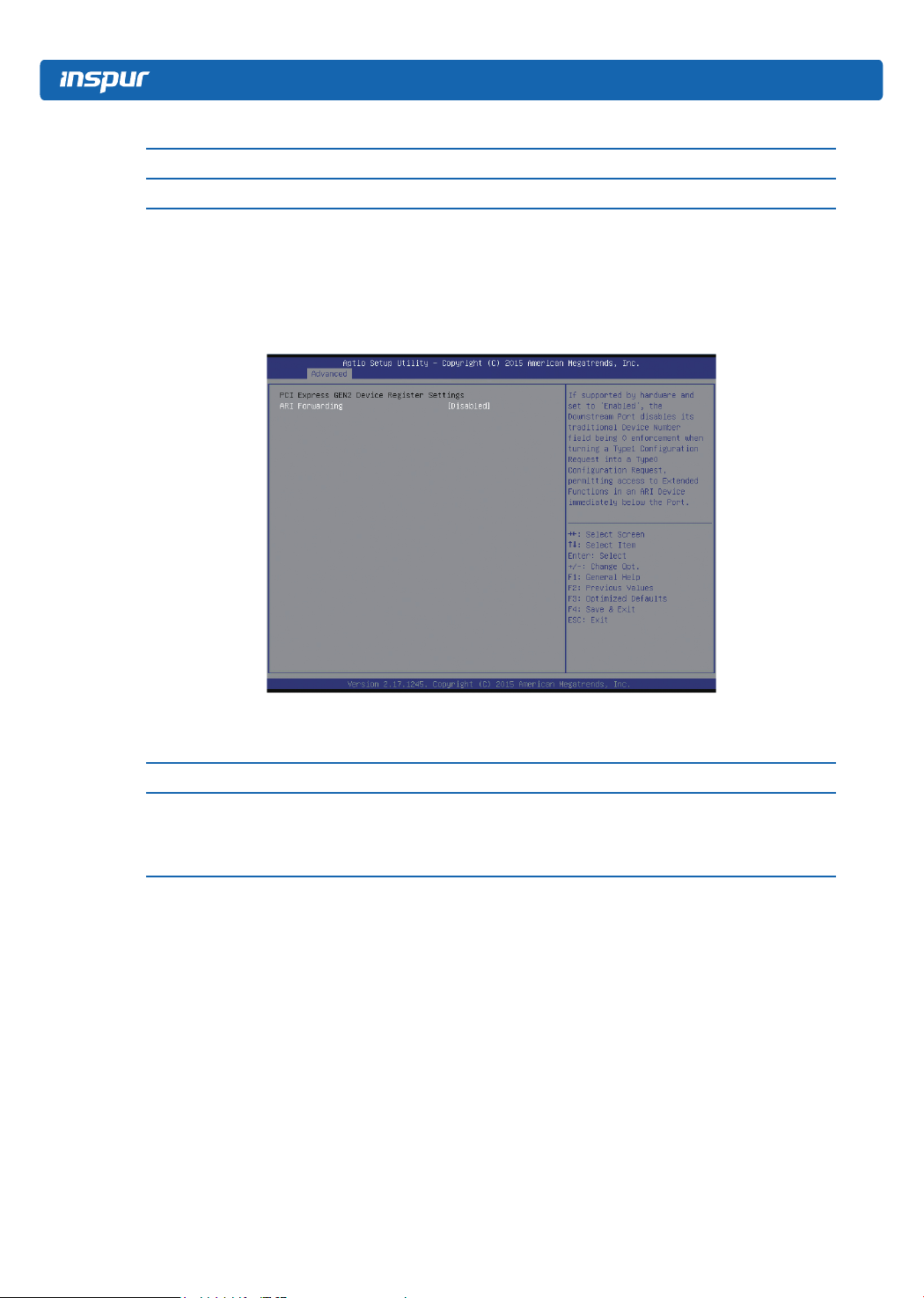
PCI Express GEN 2 Settings
PCI Express GEN 2 Settings interface is used to set the options related with PCIe
subsystem, as shown below:
Parameter description of PCI Express GEN 2Settings interface:
Parameters Function description
On-off setting of ARI forwarding function. If enabled, there is only one
ARI Forwarding
device in one bus, the device ID will be ignored, so that one device can
have 256 functions.
3.2.2.4 Network Stack Configuration
Network Stack Conguration interface is used to set the options related with network
module, as shown below:
16
 Loading...