

Inspur NF5180M4 User Manual

INSPUR SERVER USER MANUAL
NF5180M4
V1.0

Copyright Introduction
Document version: V1.0
Date: 13
th
April. 2015
Document Introduction: The 1st formal issuance.
Abstract
The manual introduces issues closely related to maintenance such as specification,
hardware operation, software conguration, service terms, fault diagnosis etc. of the server.
Readers of this guide will be deemed to have abundant knowledge about the server
product, and will not cause any personal injury or product damage during operation and
maintenance, for sufcient trainings received by them.
Target Audience
This manual mainly adapts to the following personnel:
● Technical support engineers
● Product maintenance engineers
It is suggested that server maintenance operation shall be carried out by professional
engineers with related server knowledge via referring to this manual.

Warning:
This manual introduces this server’s technical features and system installation and
setup, which helps you to particularly understand and expediently use this server.
①
Please do not disassemble the server’s components arbitrarily. Please do not
extend conguration or connect other peripheral devices arbitrarily. If needed,
please be sure to conduct it with our authorization and guidance.
②
Before disassembling the server’s components, please be sure to disconnect all
the power cords connected to the server.
③
BIOS and BMC setup is signicant to the conguration of your server. If there
are no special requirements, you are suggested to use the default value and not
alter the parameter settings arbitrarily.
Advertencia:
Este manual describe las características técnicas de este servidor, y la conguración
e instalación del sistema, le ayudará a la comprensión más detallada y fácil al uso del
servidor.
①
Por favor, no desmonte los componentes del servidor, no amplie o conecte
arbitrariamente otros dispositivos equipados. Cuando necesita hacer algún
operación, asegúrese hacerla bajo nuestra autorización y orientación.
②
Antes del desmontaje del componente del servidor, asegúrese de desconectar
todos los cables conectados al servidor.
③
Los ajustes de BIOS y BMC son muy importantes. Si no hay requisitos
especiales, por favor, utilice la configuración por defecto del sistema y no
cambie los parámetros de la conguración.

Table of Content
1 SAFETY INTRODUCTION ...................................................................................................... 1
2 PRODUCT SPECIFICATION INTRODUCTION ................................................................. 6
2.1 Introduction ......................................................................................................................... 6
2.2 Features and Specication .................................................................................................. 7
2.3 Front Panel .......................................................................................................................... 9
2.4 Rear Panel ........................................................................................................................... 11
2.5 Mainboard Layout ............................................................................................................... 12
2.6 Mainboard Jumper Introduction ......................................................................................... 14
3 BIOS CONFIGURATION ......................................................................................................... 15
3.1 System BIOS Conguration Methods ................................................................................ 15
3.2 BIOS Conguration ............................................................................................................ 16
3.3Firmware Update ................................................................................................................. 47
4 BMC CONFIGURATION ........................................................................................................... 51
4.1 Introduction ......................................................................................................................... 51
4.2 Functional Modules ............................................................................................................ 52
4.3 Web Interface Introduction ................................................................................................. 53
4.4 Remote Control ................................................................................................................... 57
4.5 Power Supply and Heat Radiation ...................................................................................... 58
4.6 BMC Conguration ............................................................................................................ 59
4.7 Logs .................................................................................................................................... 63
4.8 Fault Diagnosis ................................................................................................................... 64
4.9 System Maintenance ........................................................................................................... 65
4.10 Command Line Function Introduction ............................................................................. 66
4.11 Time Zone Table ............................................................................................................... 71

5 HARDWARE MAINTENANCE ............................................................................................... 73
5.1 Tool Preparation .................................................................................................................. 73
5.2 Parts Replacement ............................................................................................................... 73
6 FREQUENT FAULTS, DIAGNOSIS AND TROUBLESHOOTING ..................................... 82
6.1 Frequent Faults ................................................................................................................... 82
6.2 Diagnosis and Exclusion Instructions ................................................................................. 83
7 SPECIFICATIONS ...................................................................................................................... 86
7.1 USA FCC Statement ........................................................................................................... 86
7.2 CE Statement of EU ............................................................................................................ 86
7.3 China CCC .......................................................................................................................... 86
7.4 China Environmental Symbols ........................................................................................... 87

1
Safety Introduction
1 Safety Introduction
Warning: the following warnings show that there are potential dangers that may cause
property loss, personal injury or death:
1. The power supply equipment in the system may generate high voltage and dangerous
electrical energy and thus cause personal injury. Please do not dismount the cover of
the host or to dismount and replace any component in the system by yourself, unless
otherwise informed by Inspur; only maintenance technicians trained by Inspur have the
right to disassemble the cover of the host, dismount and replace the internal components.
2. Please connect the equipment to appropriate power supply, and the power should
be supplied by external power supply which is indicated on the rated input label. To
prevent your equipment from damages caused by momentary spike or plunge of the
voltage, please use relevant voltage stabilizing equipment or uninterruptible power
supply equipment.
3. If extended cables are needed, please use the three-core cables matched with correct
earthed plug, and check the ratings of the extended cables to make sure that the sum of
rated current of all products inserted into the extended cables do not exceed 80% of the
limits of the rated currents of the extended cables.
4. Please be sure to use the supplied power supply component, such as power lines, power
socket (if supplied with the equipment) etc. For the safety of equipment and the user, do
not replace randomly power cables or plugs.
5. To prevent electric shock dangers caused by leakage in the system, please make sure
that the power cables of the system and peripheral equipment are correctly connected
to the earthed power socket. Please connect the three-core power line plug to the three-
core AC power socket that is well earthed and easy to access, be sure to use the earthing
pin of power lines and do not use the patch plug or the earthing pin unplugged with
cables. In case of the earthing conductors not installed and it is uncertain whether there
are appropriate earthing protections, please do not operate or use the equipment. Contact
and consult with the electrician.
6. To avoid short circuit of internal components and re or electric shock hazards, please
do not ll any object into the open pores of the system.

2
7. Please place the system far away from the cooling plate and at the place with heat
sources, and be sure not to block the air vents.
8. Be sure not to scatter food or liquid in the system or on other components, and do not
use the product in humid and dusty environment.
9. CAUTION: Risk of Explosion if Battery is replaced by an Incorrect Type. Dispose of
Used Batteries According to the Instructions.
ATTENTION: risque d'explosion si la batterie est remplacée par un type incorrect. Jetez
les piles usagées selon les instructions.
The replacement of batteries with those of incorrect model may cause explosion. When
replacement of batteries is required, please consult rst the manufacturer and choose
batteries of the same or a similar model recommended by the manufacturer. Do not
dismount, extrude and pink the batteries or make the external connection point short
circuit, and do not expose them in the environment over 60°C. Never throw them into
re or water. Please do not try to open or repair the batteries, and be sure to reasonably
deal with the at batteries and do not put the at batteries, the circuit boards that may
include the batteries and other components with other wastes. For relevant battery
recovery, please contact the local waste recovery and treatment mechanism.
10. Before installing equipment in the chassis, please install front and side supporting feet
on the independent chassis; for cabinet connecting with other chassis, it shall install
the front supporting foot rst. If you fail to install correspondingly the supporting foot
before installing equipment in the chassis, it may cause the cabinet to turn over in some
cases, and thus may cause personal injury. Therefore, it is necessary to install supporting
feet before installing equipment in the chassis. After installing the equipment and other
components in the chassis, it can only pull out one component from the cabinet through
its sliding component at one time. Pulling out several components at the same time may
lead the cabinet to turn over and cause serious personal injury.
11. Please do not move the chassis independently. Considering the height and weight of the
chassis, at least two people are needed to complete its movement.
12. Please do not carry out direct contact operation on power copper busbar when the
cabinet is powered on, and it is prohibited to carry out direct short circuit of power
copper busbar.
13. The product is Grade A product, and in the living environment, it may cause radio
interference. In such case, it may need the user to take feasible measures for the interference.

3
Safety Introduction
14. Equipment intended for installation in Restricted Access Location.
équipement conçu pour une installation dans Emplacement à accès restraint.
Note: In order to help you use the equipment, the following considerations can help avoid the
occurrence of problems that may damage the components or cause data loss etc.
1. In case of the following cases, please unplug the power line plug of products from the
power socket and contact customer service department of Inspur:
1) The power cables, extended cables or power plugs are damaged.
2) The products get wet by water.
3) The products have fallen off or been damaged.
4) Objects fall into the products.
5) When operating according to the operation instructions, the products cannot
function normally.
2. If the system becomes damp, please dispose according to the following steps:
1) Switch off the power supplies of the system and the equipment, disconnect them
with the power socket, wait for 10 to 20 minutes, and then open the cover of the
host.
2) Move the equipment to the ventilation place to dry the system at least for 24 hours
and make sure that the system is fully dried.
3) Close the cover of the host, re-connect the system to the power socket, and then
start the equipment.
4) In case of operation failure or abnormal situation, please contact Inspur and get
technical support.
3. Pay attention to the position of the system cables and power cables, wire them in places
not to be stepped on or knocked down and ensure not to place other objectives on the
cables.
4. Before dismounting the cover of host or contacting the internal components, you shall
cool down the equipment rst; to avoid damaging the main-board, please power off the
system and wait for 5 seconds, and then dismount the components from the main-board
or disconnect the connection of peripheral equipment of the system.
5. If there are modulator-demodulator, telecommunication or local area network options in
the equipment, please pay attention to the following matters:

4
1) In case of thunder and lightning weather, please do not connect or use the
modulator-demodulator. Otherwise, it may be subject to lightning strike.
2) Never connect or use modulator-demodulator in moist environment.
3) Never insert the modulator-demodulator or telephone cables to the socket of
network interface controller (NIC).
4) Before unpacking the product package, contacting or installing internal components
or contacting un-insulated cables or jacks of the modulator-demodulator, please
disconnect the modulator-demodulator cables.
6. In order to prevent the electrostatic discharge from damaging the electronic components
in the equipment, please pay attention to the following matters:
1) You shall conduct off the static electricity on the body before dismounting or
contacting any electronic component in the equipment. You can conduct off the
static electricity on the body by contacting the metal earthing objects (such as the
unpainted metal surface on the chassis) to prevent the static electricity on the body
from conducting itself to the sensitive components.
2) For electrostatic sensitive components not ready to be installed for application,
please do not take them out from the antistatic package materials.
3) During the work, please touch the earthing conductor or the unpainted metal surface
on the cabinet regularly to conduct off the static electricity on the body that may
damage the internal components.
7. When dismounting the internal components with the approval of Inspur, please pay
attention to the following matters:
1) Switch off the system power supply and disconnect the cables, including
disconnecting any connection of the system. When disconnecting the cables, please
grab the connector of cables and plug it out, and never pull the cables.
2) Before dismounting the cover of cabinet or touching the internal components, the
products need to be cooled down.
3) Before dismounting and touching any electronic component in the equipment,
you shall conduct off the static electricity on the body by touching the metal
earthingobjectives.
4) During the dismounting process, the operation shall not be too big, so as to prevent
damage to the components or scratching of the arms.
5) Carefully deal with the components and plug-in cards, and please never touch, the

5
Safety Introduction
components or connection points on the plug-in cards. When taking the plug-in
cards or components, you should grab the edges of the plug-in cards or components
or their metal xed supports.
8. During the process of cabinet installation and application, please pay attention to the
following matters:
1) After the installation of cabinet is nished, please ensure that the supporting feet
have been xed to the rack and supported to the ground, and all weight of the rack have been
fell onto the ground.
2) It shall install into the cabinet according to the sequences from the bottom to the
top, and rst install the heaviest component.
3) When pulling out the components from the cabinet, it shall apply force slightly to
ensure the cabinet to keep balance and stabilization.
4) When pressing down the release latch of the sliding rail of components and sliding
in or out, please be careful, as the sliding rail may hurt your gures.
5) Never make the AC power branch circuit in the cabinet overload. The sum of
cabinet load shall not exceed 80% of the ratings of branch circuits.
6) Ensure that components in the cabinet have good ventilation.
7) When repairing components in the cabinet, never step on any other components.
6
2. Product Specication Introduction
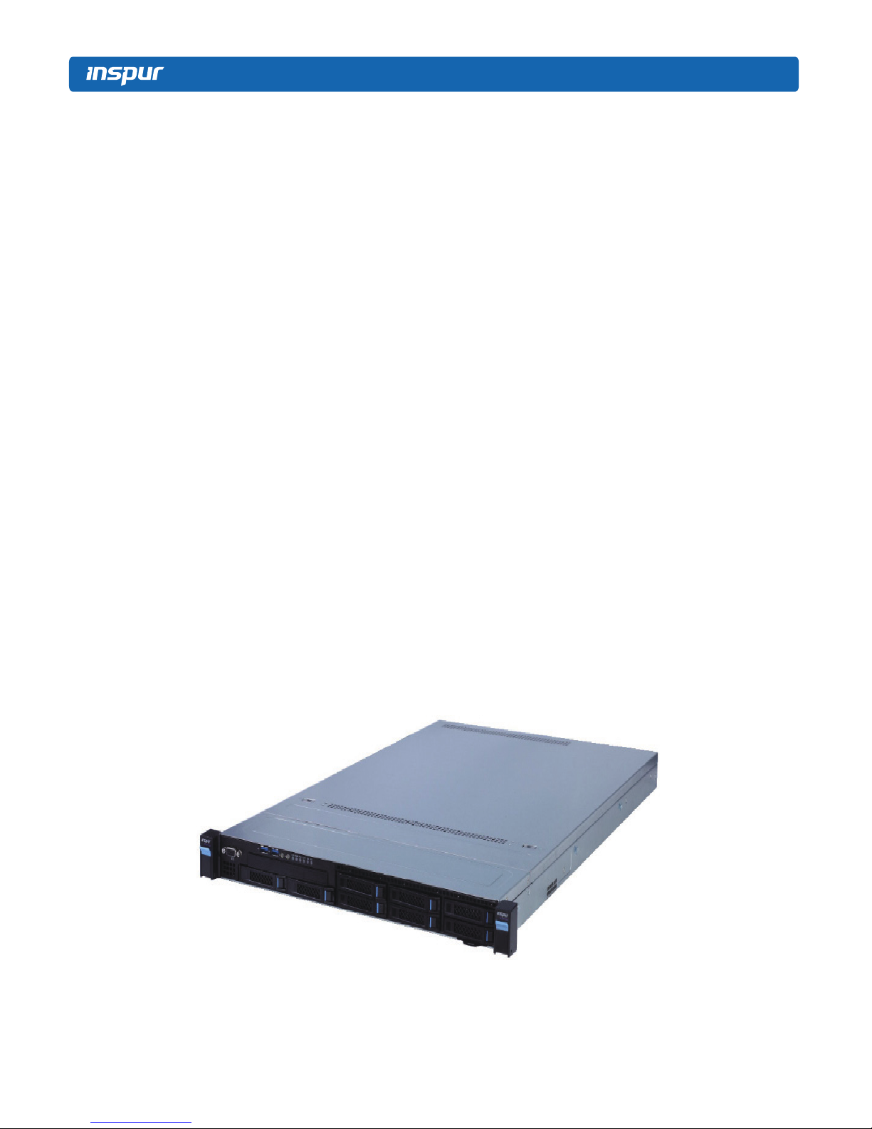
2.1 Introduction
This type is a kind of server product developed independently. It adopts Intel Grantley-
EP platform, and uses Wellsburg chip set. It supports two mainstream Intel Xeon E5-26**
V3 series processors. It supports 24 DIMM DDR4 memory, up to 2133MHz. It supports
ECC Registered and multiple senior memory redundancy functions. It supports up to 2.5”
x8 SAS/SATA/SSD hot-plugging hard disks or 3.5” x4 SAS/SATA/SSD hot-plugging hard
disks. Mainboard integrates a Gigabit net card of high performance, and supports network
advanced features. Mainboard integrates BMC/KVM chips. 7 PCI-Express expansion slots
are available.
Supports SAS 3.0 (12Gb/s) or SAS Raid cards, and implements flexible SAS/SAS
RAID solutions. Modular design on components such as structure, storage, PCI expansion,
power supply and fan etc. Energy-saving and noise reduction design, equipped with PMbus
power supply of high efciency, supports DPNM function, and implements energy saving
and consumption reducing.
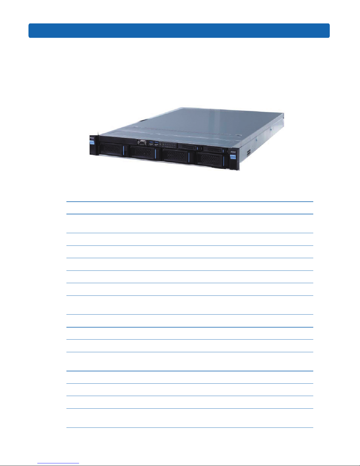
●
2.5”×8 conguration (i.e. full conguration)
It supports 8 front set 2.5” SAS/SATA/SSD hard disks, and the related appearance is as
shown in the following gure.
7
Product Specication Introduction
●
3.5”×4 conguration (i.e. full conguration)
It supports 4 front set 3.5/2.5” SAS/SATA/SSD hard disks, and the related appearance is
as shown in the following gure.
Note: 3.5” hard disk bracket could hold 3.5”/2.5” hard disks.
2.2 Features and Specication
Processor
Processor Type
Intel dual-way Xeon E5-26XX V3 Series (supports up to two
145W)
Interface Two Socket-R3 slots.
Chip Group
Chip Group Type PCH C610(Wellsburg)
Memory
Memory Type DDR4 ECC RDIMM/LRDIMM memory
Single Inline Memory
Module Qty.
24
Memory Volume It supports up to 1536GB (64GB for single)
I/O Interface
USB Interface 2 rear set USB 3.0 interfaces, and 2 built-in USB 3.0 interfaces
Display Interface
1 front set VGA interface
1 rear set VGA interface
Serial Interface 1 built-in serial port
ID Indicator Interface 1 ID indicator (blue) and its press button
Display Controller
Controller Type
A speed 2400 integrated in chip, with max. resolution supporting
1280*1024

8
SAS Backplane
SAS3.0 backplane It supports hog-plugging SAS/SATA/SSD hard disks.
Network Card
Network Card ontroller
The mainboard integrates 1 Intel I350 dual Gigabit network card,
providing two 1000M adaptive RJ45 network ports.
It supports 1 network sub-card.
Management Chip
Management Chip
It integrates 1 independent 1000Mbps network interface, which is
used in IPMI remote management.
PCI Extension Slot
● There’re 2 onboard PCI Express 3.0 x24 slots on the mainboard
(used to support PCI-E Riser card)
● Riser card supports horizontal cards and full-height cards.
● Standard conguration:
PCIE0 slot (from CPU0) installed with a Riser card could support 1
PCI Express 3.0x8 slots.
● Full conguration :
PCIE0 slot (from CPU0) installed with a Riser card could support 1
PCI Express 3.0x8 slots;
PCIE1 slot (from CPU1) installed with a Riser card could support 1
PCI Express 3.0x8 slots.
Hard Disk
Hard Drive Type
Front set 2.5/3.5 inches SAS, SATA and SSD hard disks. (Subject
to actual type you purchased)
Front set 2.5/3.5 inch SAS, SATA and SSD hard disks; (Subject to
actual type you purchased)
External Storage Driver
CD Driver
It supports Slim SATA interface DVD driver (9.5 mm)
External USB drive.
Drive U Disk Optional drive U disk.
Power Supply
Specication
Output power of sing/Double power 550W/800W and above; 1+1
redundancy; 2 power modules; it supports PMBus power supply,
and implements Node Manager 3.0 function.
Power Input Please refer to power input on nameplate tag of the host.
Physical Specication
External Dimension of
Package
635 width × 215 height × 955 depth (unit: mm)

9
Product Specication Introduction
Host Size 430 width × 44 height × 730 depth (unit: mm)
Product Weight
Gross weight: 26kg. (Gross weight includes: Host + Packing Box +
Rail + Parts Kit)
Environment
Parameters
Working Environment
Temperature
10℃-35
℃
Storage & Transportation
Temperature
-40℃-55
℃
Working Humidity 35%-80% relative humidity
Storage & Transportation
Humidity
20%-93%(40℃) relative humidity
2.3 Front Panel
2.3.1 2.5×8 Disk Position
No. Module Name
1 Server is xed with the cabinet
2 Front set VGA interface
3 Front set USB 3.0 interface
4 Server switch button
5 ID light and button
6 System fault indicator button
7 Front set hard disk slot
2.5×8 disk position hard disk sequence diagram
10
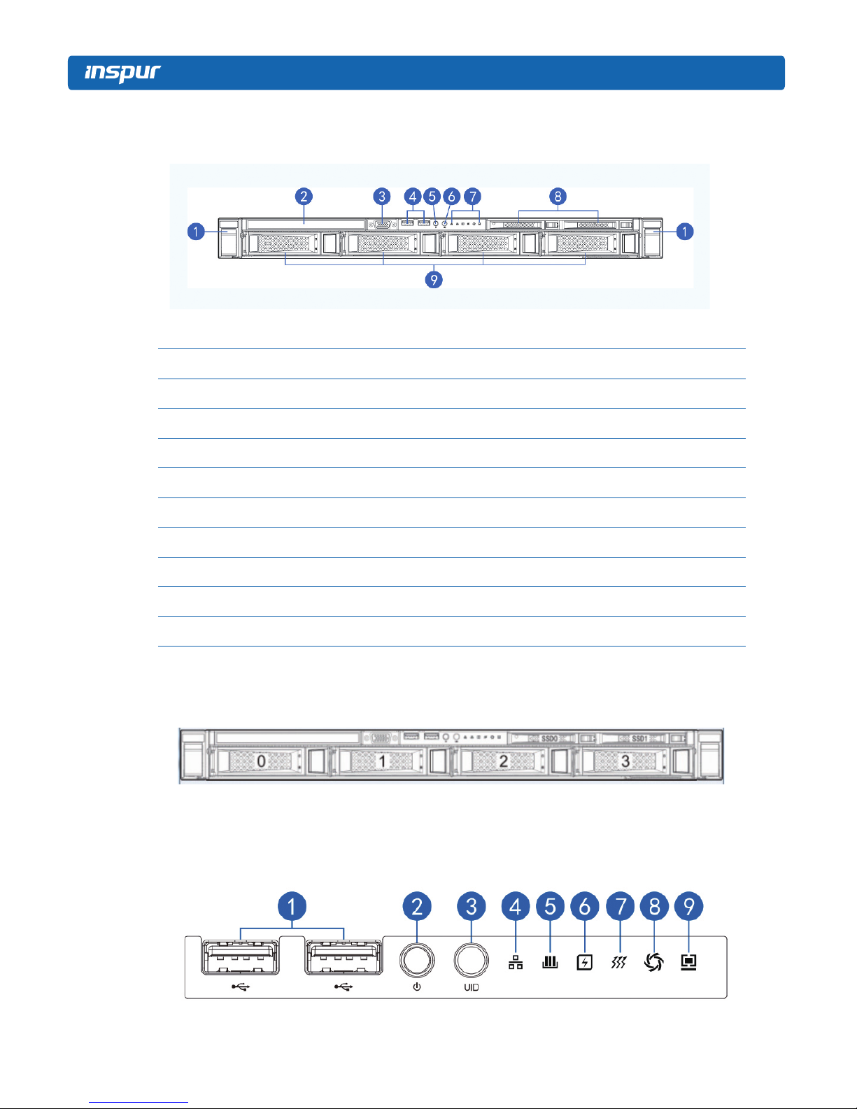
2.3.2 3.5×4 Disk Position
No. Module Name
1 Server is xed with the cabinet
2 CD Driver
3 Front set VGA interface
4 Front set USB 3.0 interface
5 Server switch button
6 ID light and button
7 System fault indicator button
8 Front set SSD hard disk slot
9 Front set hard disk slot
3.5×8 disk position hard disk sequence diagram
2.3.3 Front Control Panel Buttons and Indicators
11
Product Specication Introduction
No. Module Name
1 USB interface
2 Server switch button
3 ID light and button
4 Network status indicator
5 Memory fault indicator
6 Power fault indicator
7 System overheating indicator
8 Fan fault indicator
9 System fault indicator
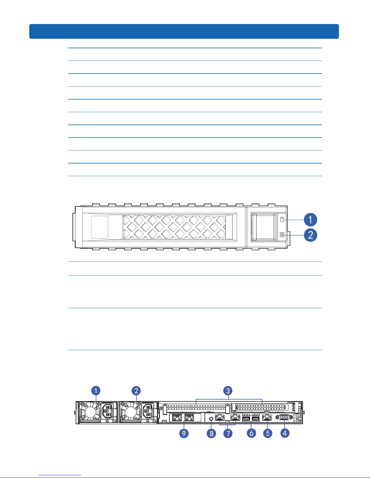
2.3.4 Indicators on Hard Disk Bracket
Number Module Name Description
1 Hard disk activity status indicator
Constant green: Normal
Flashing green: Hard disk is reading and
writing
2 Hard disk fault alarming indicator
Constant red: Hard disk fault
Constant blue: Hard disk positioning
Constant blue: In coordination with RAID
rebuilding
2.4 Rear Panel
12
No. Module Name
1 Power supply 0
2 Power supply 1
3 PCIE slot 0-1
4 VGA interface
5 IPMI management interface
6 USB 3.0 interface
7 Gigabit network port
8 ID light and button
9 Network sub card slot
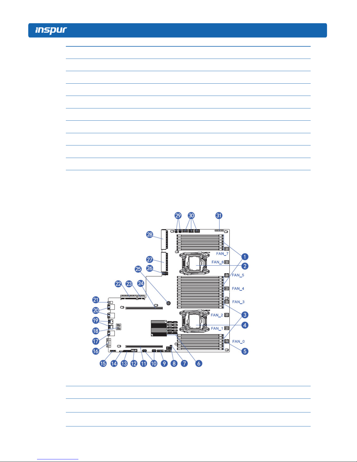
2.5 Mainboard Layout
No. Module Name
1 Memory slot (corresponding with CPU1)
2 CPU1

13
Product Specication Introduction
No. Module Name
3 Memory slot (corresponding with CPU0)
4 CPU0
5 System fan interfaces (8 interfaces in all)
6 SATA interface
7 CMOS clear jumper
8 CPU0 supply interface
9 Front set USB interface
10 Built-in USB interface
11 PCIE Riser card interface (corresponding with CPU0)
12 Built in serial ports
13 TPM interface
14 IPMB interface
15 Front set VGA interface
16 Rear set VGA interface
17 IPMI management interface
18 Debug light
19 Rear set USB interface
20 Gigabit network port
21 ID light and button
22 Network sub-card data interface
23 Network sub-card management interface
24 PCIE Riser card interface (corresponding with CPU1)
25 Mainboard xing catch
26 CPU1 supply interface
27 Power 1 Interface
28 Power 2 Interface
29 Rear set hard disk backplane power interface
30 Front set hard disk backplane power interface
31 Front control panel interface

14
2.6 Mainboard Jumper Introduction
2.6.1 Clear CMOS Jumper Introduction
See [2.5 Mainboard Layout] for jumper positions.
Jumper No. Function Description Jumper Functions
CLR_CMOS CMOS clear jumper
Short-circuit pin1-2, to restore normal status; short-
circuit pin2-3, to clear CMOS.
Note:It is required to shut down the system, as well as disconnect power supply during
CMOS cleaning, and hold for 5 seconds after short-circuiting Pin2-3; then short-circuit Pin1
and Pin2 of CLR_CMOS jumper with a jumper cap (the default status), to restore its original
status.
15
BIOS Conguration
3 BIOS Conguration
This chapter introduces BIOS function setup and mainboard jumper of the server. All
operations described in this section are only limited to operators or administrators with
system maintenance qualication.
BIOS is a basic input and output system. The system parameter and the hard drive
parameter can be adjusted through special set program. BIOS has great influence on the
system start and running so that setting parameters improperly may arose the conict among
the hardware resource, or fall down the system run performance. Hence understanding the
BIOS setup is signicant to the conguration of your server. If no especial requirement, you
are suggested to use the default value and not alter the parameters optionally.
1. Before the server BIOS setup is altered, please record the corresponding original setup. Hence
when there are operating problems in the system due to the option altered, the setup can revert.
2. Ordinarily the factory default system value is the optimized setup. Don’t try to alter the
parameters before you understand their denotations.
3. The common setup is introduced in detail in this paper. The less referred options in the
application procedure are simply explained or not.
4. The content of the BIOS is diverse based on the different congurations of the products; hence
the detailed introduction is elided.
3.1 System BIOS Conguration Methods
Power on the server, system starts to boot, when the following content appears below
The distributor logo on the screen:
“Press <DEL> to SETUP or <TAB> to POST or <F12> to PXE Boot.”, press [DEL]
button, when “Entering Setup...” appears on bottom right on the screen, it will enter system
BIOS conguration later, and you could select options using arrow buttons on BIOS main
menu to enter sub-menu.
Note: Options in grey are not available. Options with symbol “ ”, have a sub-menu.
16
Control key instruction table
Press Key Function
<Esc> Exit or return from sub-menu to main menu.
<←>or<→> Select a menu.
<↑>or<↓> Move the cursor up or down.
<Home>or<End> Move the cursor to top or bottom of the screen.
<+>or<->
Select the previous or next numerical value or setting of the
current one.
<F1> Help
<F2> Restore the last conguration.
<F9> Restore default conguration.
<F10> Save and exit
<Enter> execute commands or select a sub-menu.
3.2 BIOS Conguration
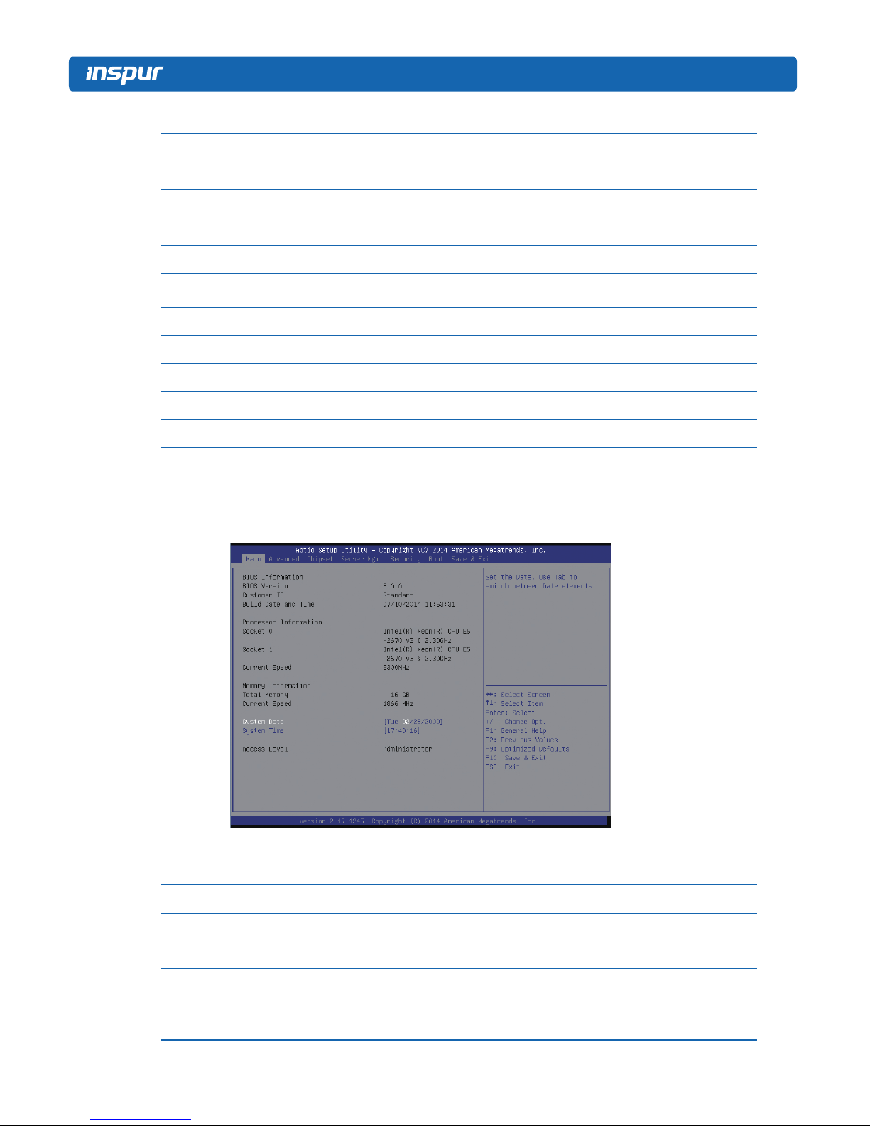
3.2.1 Main Menu
Main Menu Interface Instruction Table
Interface Parameters Function Description
BIOS Information Displays current BIOS information.
Processor Information Displays CPU information.
Memory Information Displays memory volume and current speed.
System Date(Day mm/dd/yyyy)
System Time (hh/mm/ss)
Displays system time.
Access Level Current access level
17
BIOS Conguration
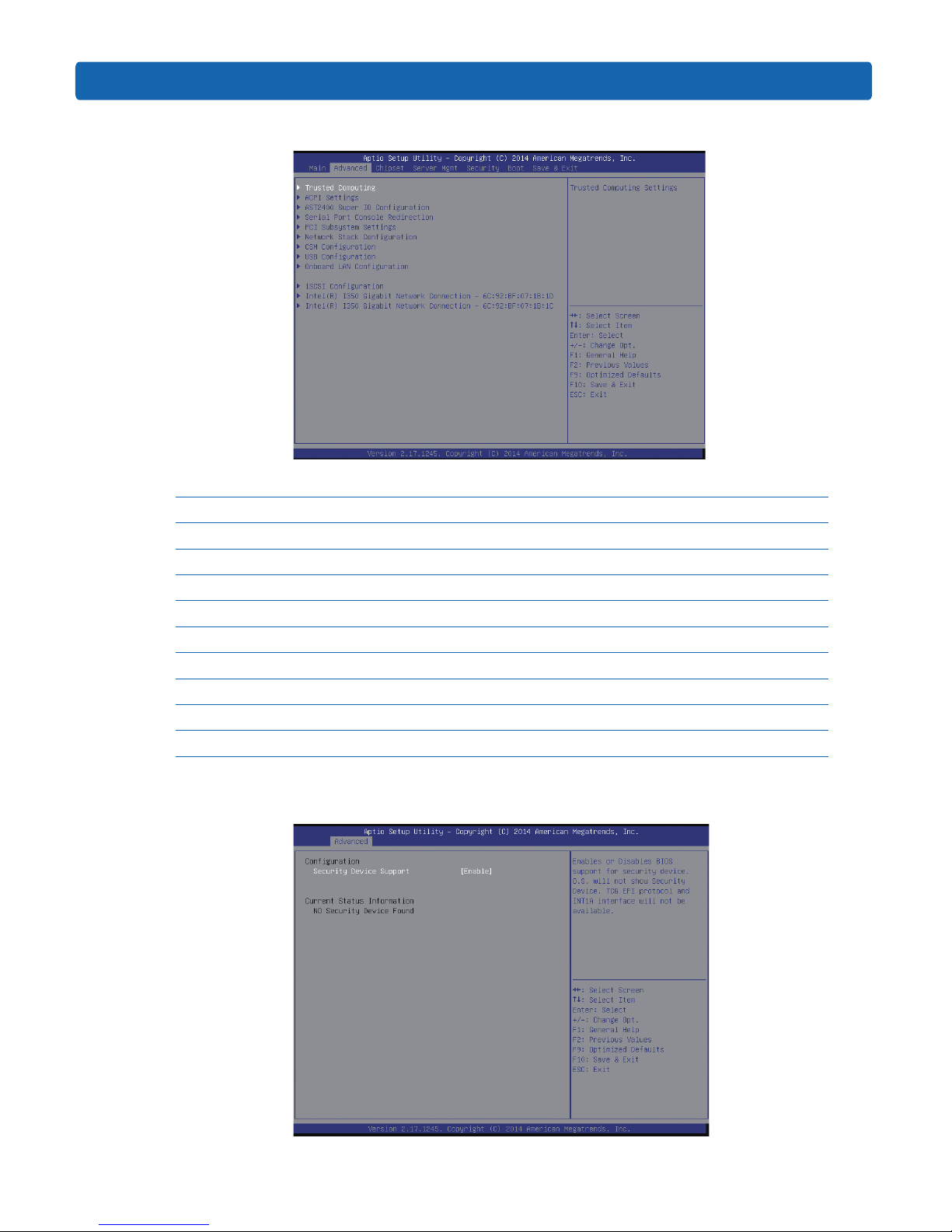
3.2.2 Advanced Menu
Advanced Menu Interface Instruction Table
Interface Parameters Function Description
Trusted Computing Trustable computing conguration
ACPI Settings Advanced conguration and power interface settings
AST2400 Super IO Conguration AST2400 I/O chip parameter conguration
Serial Port Console Redirection Serial port console redirection settings
PCI Subsystem Settings PCI subsystem settings
Network Stack Conguration Network stack conguration
CSM Conguration CMS conguration
USB Conguration USB conguration
Onboard LAN Conguration Onboard network card conguration
3.2.2.1 Trusted Computing
18
Trusted Computing Menu Interface Instruction Table
Interface Parameters Function Description
Security Device Support BIOS’s security device support settings
Current Status Information Status information of the current security device
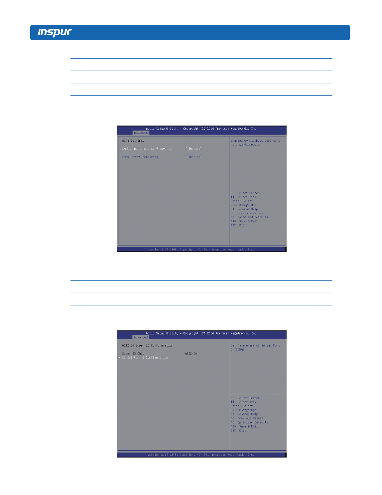
3.2.2.2 ACPI Settings
Advanced Menu Interface Instruction Table
Interface Parameters Function Description
Enable ACPI Auto Conguration To allow ACPI’s automatic conguration.
Lock Legacy Resources The locking legacy resources setting
3.2.2.3 AST2400 Super IO Configuration
19
BIOS Conguration
AST2400 Super IO Conguration Menu Interface Instruction Table
Interface Parameters Function Description
Super IO Chip The current I/0 chip
Serial Port 1 Conguration Serial port 1 conguration
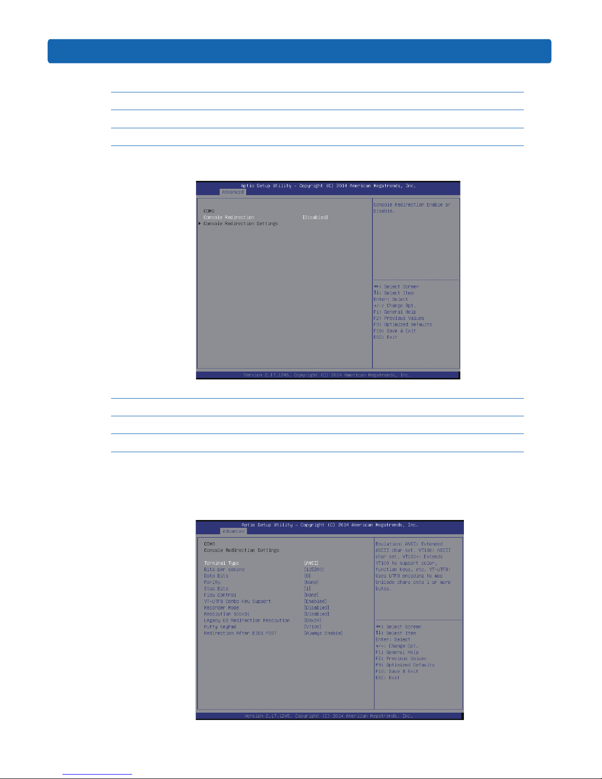
3.2.2.4 Serial Port Console Redirection
Serial Port Console Redirection Menu Interface Instruction Table
Interface Parameters Function Description
Console Redirection The console redirection switching settings
Console Redirection Settings The console redirection parameter settings
3.2.2.4.1 Console Redirection Settings
When the Console Redirection option is set to [Enabled], the Console Redirection
Settings menu is started.
20
Console Redirection Settings Menu Interface Introduction
Interface Parameters Function Description
Terminal Type Terminal type settings
Bits per second Baud rate settings
Data Bits Data bits settings
Parity Parity check settings
Stop Bits Stop bits settings
Flow Control Flow control settings
VT-UTF8 Combo Key Support VT-UTF8 Combo key support settings
Recorder Mode Recorder mode settings
Redirection 100×31 Expanded terminal resolution settings
Legacy OS Redirection Resolution Terminal resolution settings of legacy OS
Putty KeyPad Putty’s functional keys and keyboard settings
Redirection After BIOS POST Redirection after BIOS bootup settings
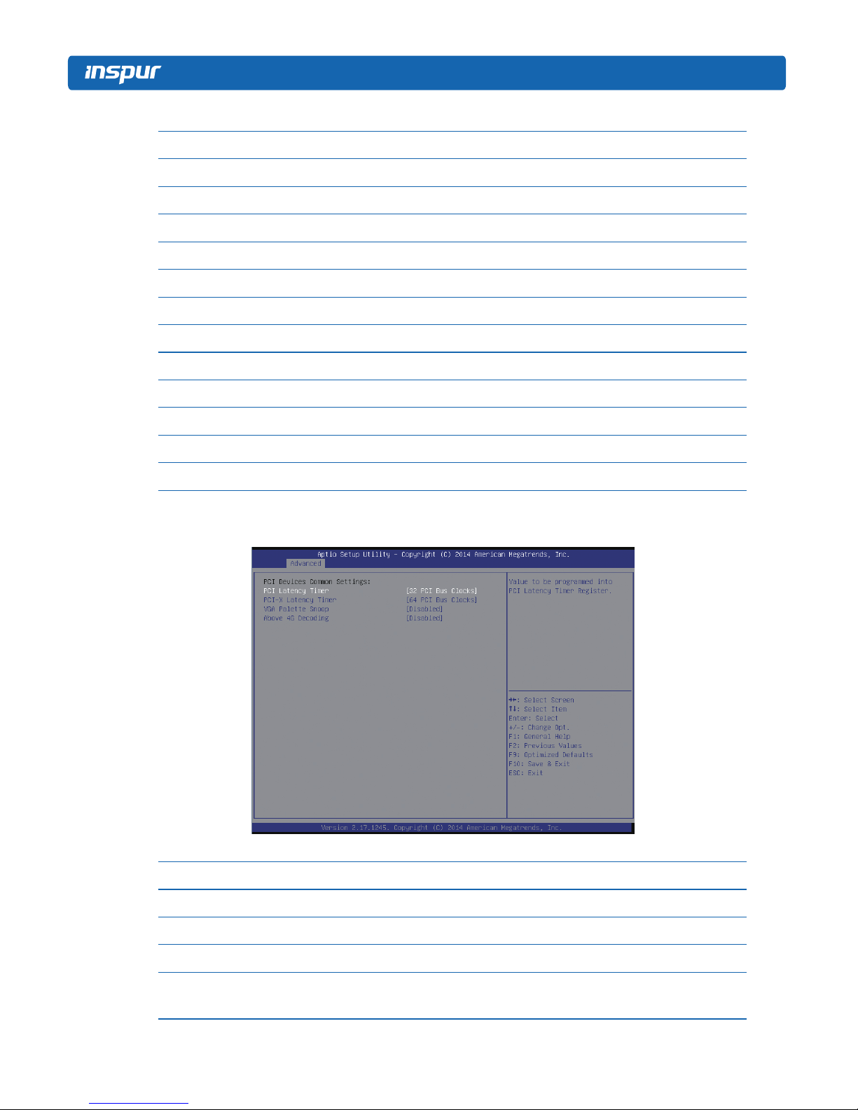
3.2.2.5 PCI Subsystem Settings
PCI Subsystem Settings Menu Interface Instruction Table
Interface Parameters Function Description
PCI Latency Timer PCI delay timer settings
PCI-X Latency Timer PCI-X delay timer settings
VGA Palette Snoop VGA color correction settings
Above 4G Decoding
64bit equipment’s decoding settings on address space
larger than 4G.
21
BIOS Conguration
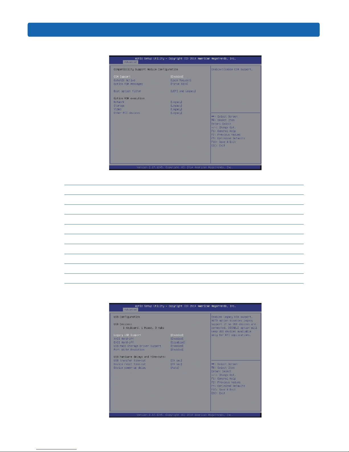
3.2.2.6 CSM Configuration
CSM Conguration Menu Interface Instruction Table
Interface Parameters Function Description
CSM Support CSM support settings
GateA20 Active A20 address line’s control mode settings
Option Rom Message Option Rom display mode settings
Boot option lter Boot option lter settings
Option ROM execution Option Rom execution method
Network Network card Option Rom execution method settings
Storage Storage device Option Rom execution method settings
Video Video device Option Rom execution method settings
Other PCI devices Other PCI devices Option Rom execution method settings
3.2.2.7 USB Configuration
22
USB Menu Interface Instruction Table
Interface Parameters Function Description
Legacy USB Support Legacy USB device settings
XHCI Hand-off
Expansible host controller interface settings, orienting to
USB 3.0.
EHCI Hand-off
Enhanced host controller interface settings, orienting to
USB2.0.
USB Mass Storage Driver Support USB mass storage driver support settings
Port 60/64 Emulation USB port 60/64h emulation settings
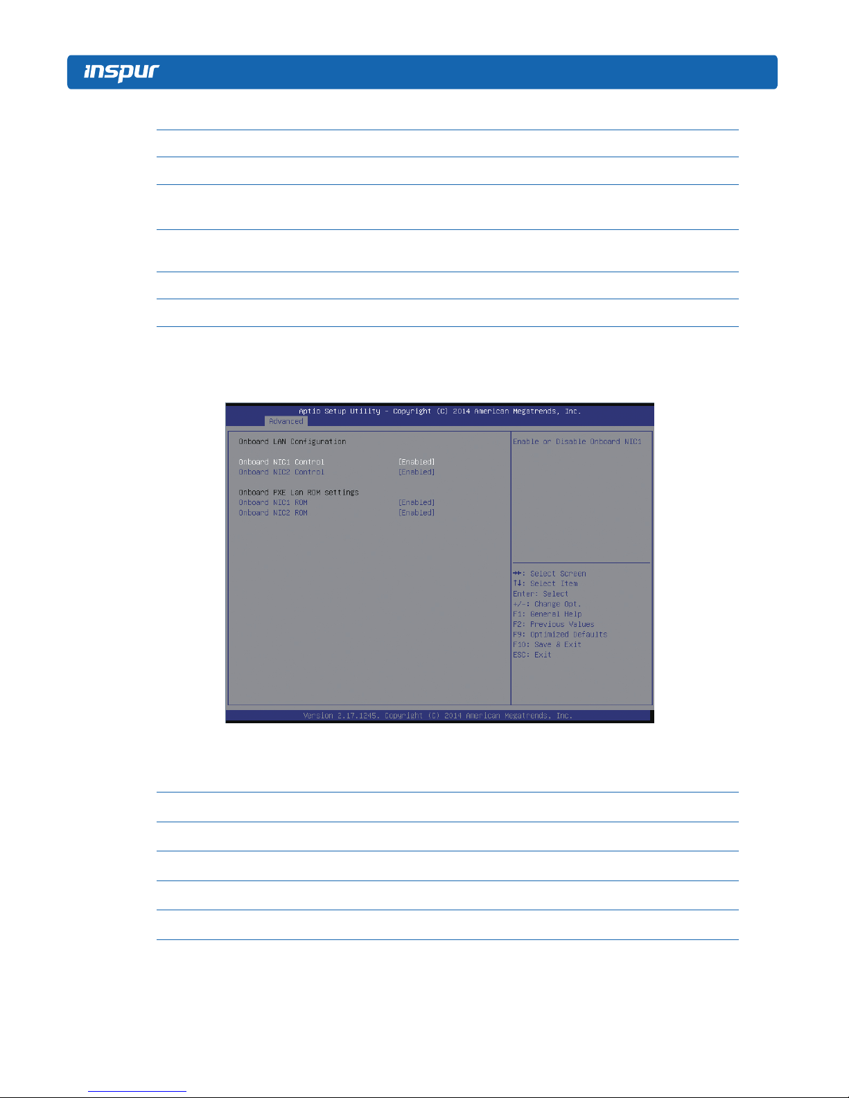
3.2.2.8 Onboard LAN Configuration
Onboard LAN Conguration Menu Interface Instruction Table
Interface Parameters Function Description
Onboard NIC1 Control Onboard network card NIC1 switching settings
Onboard NIC2 Control Onboard network card NIC2 switching settings
Onboard NIC1 ROM Onboard network card NIC1 PXE Oprom switching settings
Onboard NIC2 ROM Onboard network card NIC2 PXE Oprom switching settings
23
BIOS Conguration
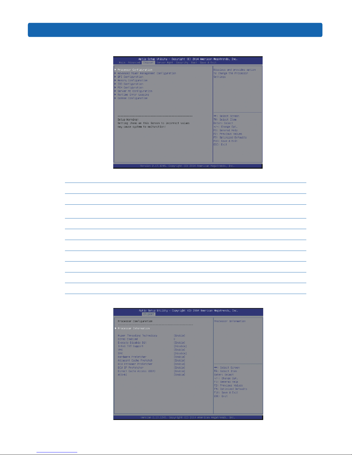
3.2.3 Chipset Menu
Chipset Menu Interface Instruction Table
Interface Parameters Function Description
Processor Conguration Processor conguration
Advanced Power Management
Conguration
Advanced power management conguration
QPI Conguration QPI conguration
Memory Conguration Memory conguration
IIO Conguration IIO conguration
PCH Conguration PCH conguration
Server ME Conguration Server ME conguration
Runtime Error Logging Runtime error log conguration
Common Conguration Common options conguration
3.2.3.1 Processor Configuration
 Loading...