

Inspur NF5166M4 User Manual

© Copyright Inspur 2016. All rights reserved.
No part of this document may be reproduced or transmitted in any form or by any
means without prior written consent of Inspur.
The information in this manual is subject to change without notice.
Inspur is the registered trademark of Inspur. All the other trademarks or registered
trademarks mentioned in this manual are the property of their respective holders.
Edition: 1
June 2016

Abstract
This manual contains technical information such as specications, hardware
operations, software conguration, fault diagnosis, etc. that are relevant to the
maintenance and operation of this server.
It is recommended that server installation, conguration, and maintenance to be
performed by experienced technicians only.
Target Audience
This manual mainly adapts to the following personnel:
● Technical support engineers
● Product maintenance engineers
It is suggested that server maintenance operation shall be carried out by professional
engineers with related server knowledge via referring to this manual.
Warnings:
TThis manual introduces the server’s technical features, system installation and
setup, which will help the user to understand how best to utilize the server and all its
functionalities.
1.For your safety, please do not disassemble the server’s components arbitrarily.
Please do not extend conguration or connect other peripheral devices arbitrarily. If
needed, please contact Inspur for our support and guidance.
2.Before disassembling the server’s components, please be sure to disconnect all
the power cords connected to the server.
3.BIOS and BMC setup is a signicant factor in correctly conguring your server. If
there are no special requirements, it is suggested to use the default values and not
alter the parameter settings arbitrarily.
4.Please use the driver shipped with the server or provided in Inspur ofcial website , if
you use non-Inspur driver, it may cause compatibility issues and affect the normal use of
the product, Inspur will not assume any responsibility or liability.
The manufacturer is not responsible for any damages, including loss of prots, loss of
information, interruption of business, personal injury, and/or any damage or consequential
damage without limitation, incurred before, during, or after the use of our products.

Table of Contents
1 Safety Instructions ........................................................................................... 1
2 Product Specications ..................................................................................... 6
2.1 Introduction ............................................................................................... 6
2.2 Features and Specications ...................................................................... 6
2.3 Front Panel ............................................................................................... 7
2.4 Rear Panel ................................................................................................ 8
2.5 Motherboard Layout .................................................................................. 9
2.6 CLR_CMOS Jumper Introductions............................................................ 10
3 BIOS Setup ...................................................................................................... 11
3.1 System BIOS Setup Methods ................................................................... 11
3.2 BIOS Settings ........................................................................................... 12
3.3 BIOS Update ............................................................................................. 62
4 BMC Settings ................................................................................................... 67
4.1 Introduction ............................................................................................... 67
4.2 Functional Modules ................................................................................... 68
4.3 Web Interface Introduction ........................................................................ 69
4.4 Command Line Introduction ...................................................................... 97
4.5 Time Zone Table ....................................................................................... 111
4.6 Key Features ............................................................................................. 113
5 Hardware Maintenance .................................................................................... 115
5.1 Tool Preparation ....................................................................................... 115
5.2 Parts Replacement ................................................................................... 115

6 Common Faults, Diagnosis and Troubleshooting ............................................ 126
6.1 Common Faults ......................................................................................... 126
6.2 Diagnosis and Troubleshooting Instructions ............................................. 127
7 Certications & Standards ............................................................................... 130
7.1 USA FCC Declaration ............................................................................... 130
7.2 CE Declaration of EU ................................................................................ 130
7.3 China CCC ................................................................................................ 131
7.4 China Environmental Labeling .................................................................. 131
Global Limited Warranty and Technical Support ................................................ 133
Hardware limited warranty .............................................................................. 133
How to obtain warranty service ...................................................................... 139
Types of warranty service ............................................................................... 140
Contacting Inspur ............................................................................................ 141

1 Safety Introduction
Warning: the following warnings show that there are potential dangers that may
cause property loss, personal injury or death:
1. The power supply equipment in the system may generate high voltage and
dangerous electrical energy and thus cause personal injury. Please do not
dismount the cover of the host or to dismount and replace any component in
the system by yourself, unless otherwise informed by Inspur; only maintenance
technicians trained by Inspur have the right to disassemble the cover of the
host, dismount and replace the internal components.
2. Please connect the equipment to appropriate power supply, and the power
should be supplied by external power supply which is indicated on the rated
input label. To prevent your equipment from damages caused by momentary
Safety Introduction
spike or plunge of the voltage, please use relevant voltage stabilizing equipment
or uninterruptible power supply equipment.
3. If extended cables are needed, please use the three-core cables matched with
correct earthed plug, and check the ratings of the extended cables to make sure
that the sum of rated current of all products inserted into the extended cables do
not exceed 80% of the limits of the rated currents of the extended cables.
4. Please be sure to use the supplied power supply component, such as power
lines, power socket (if supplied with the equipment) etc. For the safety of
equipment and the user, do not replace randomly power cables or plugs.
5. To prevent electric shock dangers caused by leakage in the system, please
make sure that the power cables of the system and peripheral equipment are
correctly connected to the earthed power socket. Please connect the three-
core power line plug to the three-core AC power socket that is well earthed and
easy to access, be sure to use the earthing pin of power lines and do not use
the patch plug or the earthing pin unplugged with cables. In case of the earthing
conductors not installed and it is uncertain whether there are appropriate
earthing protections, please do not operate or use the equipment. Contact and
consult with the electrician.
1

6. To avoid short circuit of internal components and re or electric shock hazards,
please do not ll any object into the open pores of the system.
7. Please place the system far away from the cooling plate and at the place with
heat sources, and be sure not to block the air vents.
8. Be sure not to scatter food or liquid in the system or on other components, and
do not use the product in humid and dusty environment.
9. The replacement of batteries with those of another model may cause explosion.
When replacement of batteries is required, please consult rst the manufacturer
and choose batteries of the same or a similar model recommended by the
manufacturer. Do not dismount, extrude and pink the batteries or make
the external connection point short circuit, and do not expose them in the
environment over 60°C. Never throw them into re or water. Please do not
try to open or repair the batteries, and be sure to reasonably deal with the at
batteries and do not put the at batteries, the circuit boards that may include
the batteries and other components with other wastes. For relevant battery
recovery, please contact the local waste recovery and treatment mechanism.
10. Before installing equipment in the chassis, please install front and side
supporting feet on the independent chassis; for cabinet connecting with
other chassis, it shall install the front supporting foot rst. If you fail to install
correspondingly the supporting foot before installing equipment in the chassis, it
may cause the cabinet to turn over in some cases, and thus may cause personal
injury. Therefore, it is necessary to install supporting feet before installing
equipment in the chassis. After installing the equipment and other components
in the chassis, it can only pull out one component from the cabinet through its
sliding component at one time. Pulling out several components at the same time
may lead the cabinet to turn over and cause serious personal injury.
11. Please do not move the chassis independently. Considering the height and
weight of the chassis, at least two people are needed to complete its movement.
12. Please do not carry out direct contact operation on power copper busbar when
the cabinet is powered on, and it is prohibited to carry out direct short circuit of
power copper busbar.
13. The product is Grade A product, and in the living environment, it may cause radio
interference. In such case, it may need the user to take feasible measures for the
2

Safety Introduction
interference.
Note: In order to help you use the equipment, the following considerations can help
avoid the occurrence of problems that may damage the components or cause data
loss etc.
1. In case of the following cases, please unplug the power line plug of products
from the power socket and contact customer service department of Inspur:
1) The power cables, extended cables or power plugs are damaged.
2) The products get wet by water.
3) The products have fallen off or been damaged.
4) Objects fall into the products.
5) When operating according to the operation instructions, the products cannot
function normally.
2. If the system becomes damp, please dispose according to the following steps:
1) Switch off the power supplies of the system and the equipment, disconnect
them with the power socket, wait for 10 to 20 minutes, and then open the
cover of the host.
2) Move the equipment to the ventilation place to dry the system at least for 24
hours and make sure that the system is fully dried.
3) Close the cover of the host, re-connect the system to the power socket, and
then start the equipment.
4) In case of operation failure or abnormal situation, please contact Inspur and
get technical support.
3. Pay attention to the position of the system cables and power cables, wire them
in places not to be stepped on or knocked down and ensure not to place other
objectives on the cables.
4. Before dismounting the cover of host or contacting the internal components, you
shall cool down the equipment rst; to avoid damaging the main-board, please
power off the system and wait for 5 seconds, and then dismount the components
from the main-board or disconnect the connection of peripheral equipment of
the system.
5. If there are modulator-demodulator, telecommunication or local area network
options in the equipment, please pay attention to the following matters:
3

1) In case of thunder and lightning weather, please do not connect or use the
modulator-demodulator. Otherwise, it may be subject to lightning strike.
2) Never connect or use modulator-demodulator in moist environment.
3) Never insert the modulator-demodulator or telephone cables to the socket of
network interface controller (NIC).
4) Before unpacking the product package, contacting or installing internal
components or contacting un-insulated cables or jacks of the modulator-
demodulator, please disconnect the modulator-demodulator cables.
6. In order to prevent the electrostatic discharge from damaging the electronic
components in the equipment, please pay attention to the following matters:
1) You shall conduct off the static electricity on the body before dismounting
or contacting any electronic component in the equipment. You can conduct
off the static electricity on the body by contacting the metal earthing objects
(such as the unpainted metal surface on the chassis) to prevent the static
electricity on the body from conducting itself to the sensitive components.
2) For electrostatic sensitive components not ready to be installed for
application, please do not take them out from the antistatic package
materials.
3) During the work, please touch the earthing conductor or the unpainted metal
surface on the cabinet regularly to conduct off the static electricity on the
body that may damage the internal components.
7. When dismounting the internal components with the approval of Inspur, please
pay attention to the following matters:
1) Switch off the system power supply and disconnect the cables, including
disconnecting any connection of the system. When disconnecting the
cables, please grab the connector of cables and plug it out, and never pull
the cables.
2) Before dismounting the cover of cabinet or touching the internal
components, the products need to be cooled down.
3) Before dismounting and touching any electronic component in the
equipment, you shall conduct off the static electricity on the body by
touching the metal earthingobjectives.
4) During the dismounting process, the operation shall not be too big, so as to
4

Safety Introduction
prevent damage to the components or scratching of the arms.
5) Carefully deal with the components and plug-in cards, and please never
touch, the components or connection points on the plug-in cards. When
taking the plug-in cards or components, you should grab the edges of the
plug-in cards or components or their metal xed supports.
8. During the process of cabinet installation and application, please pay attention
to the following matters:
1) After the installation of cabinet is nished, please ensure that the supporting
feet have been xed to the rack and supported to the ground, and all weight
of the rack have been fell onto the ground.
2) It shall install into the cabinet according to the sequences from the bottom to
the top, and rst install the heaviest component.
3) When pulling out the components from the cabinet, it shall apply force
slightly to ensure the cabinet to keep balance and stabilization.
4) When pressing down the release latch of the sliding rail of components and
sliding in or out, please be careful, as the sliding rail may hurt your gures.
5) Never make the AC power branch circuit in the cabinet overload. The sum
of cabinet load shall not exceed 80% of the ratings of branch circuits.
6) Ensure that components in the cabinet have good ventilation.
7) When repairing components in the cabinet, never step on any other
components.
5

2 Product Specications
2.1 Introduction
NF5166M4 is a 1U high-density storage server, supporting up to 2 Intel XEON E526**V4 processors, 16 DDR4 DIMMs, 12 3.5-inch hot-plug SAS/SATA hard disks,
4 2.5-inch hot-plug SSDs, and 2 M.2 SSDs of 2280 specication; there are 2 1GbE
network ports on the motherboard; supporting OCP NIC slot; the system uses 700W
1+1 redundant power supply.
2.2 Features and Specications
Processor
Processor type Intel 2-socket XEON E5-2600V4 series (up to 2 135w processors)
Processor interface Socket-R3 (2)
Chipset
Chipset type PCH C612 (Wellsburg)
Memory
Memory type DDR4 ECC RDIMM/LRDIMM
Memory slot Qty. 16
Total memory capacity Support up to 512GB (32G per DIMM)
I/O interface
USB interface 2 rear USB 2.0 interfaces, 1 front USB 2.0 interface
Display interface 1 rear VGA interface
Serial Interface 1 rear serial interface
ID LED interface 1 ID LED (blue) and button
Display controller
Controller type Integrated in Aspeed2400 chip, support up to 1280*1024 resolution
SAS backplane
SAS backplane
Management chip
Management chip
NIC
NIC controller
6
The internal SAS backplane supports hot-plug SAS/SATA HDDs.
The front SAS backplane supports hot-plug SSD HDDs.
Integrate 1 independent 1000Mbps network interface, special for
IPMI remote management.
1 onboard Intel I350 dual-port Gigabit NIC, provide 2 1000M
adaptive RJ45 network interfaces; support 1 external network
daughter card.
PCI expansion slot
Product Specications
PCI expansion slot
HDD
HDD type
External memory driver
USB drive Optional USB drive
Power supply
Specications
Power input Please refer to the nameplate label on the host
Physical specications
Package size W(width)721mm; H(height)279mm; D(depth)1168mm
Host size W(width)447mm; H(height)43mm; D(depth)900mm
Weight
2 onboard PCI Express 3.0 x8 slots (non-standard interfaces,
used for supporting network daughter card and SAS card)
Support up to 4 front 2.5-inch SSD HDDs, 12 internal 3.5-inch
SAS/SATA HDDs or 2.5-inch SAS HDDs, and 2 M.2 SSD HDDs.
700W and above output power; 1+1 redundancy; 2 power
modules; support PMBus power supply, realize Node Manager
3.0 function
Full conguration
Host weight: 30kg
Gross weight:41kg (it includes: Host + Packing box + Rail +
Parts box)
Environment parameter
Operating environment
temperature
Storage and transport
temperature
Operating humidity 35%-80% relative humidity
Storage and transport
humidity
10℃-35
-40℃-55
20%-93% (40℃) relative humidity
℃
℃
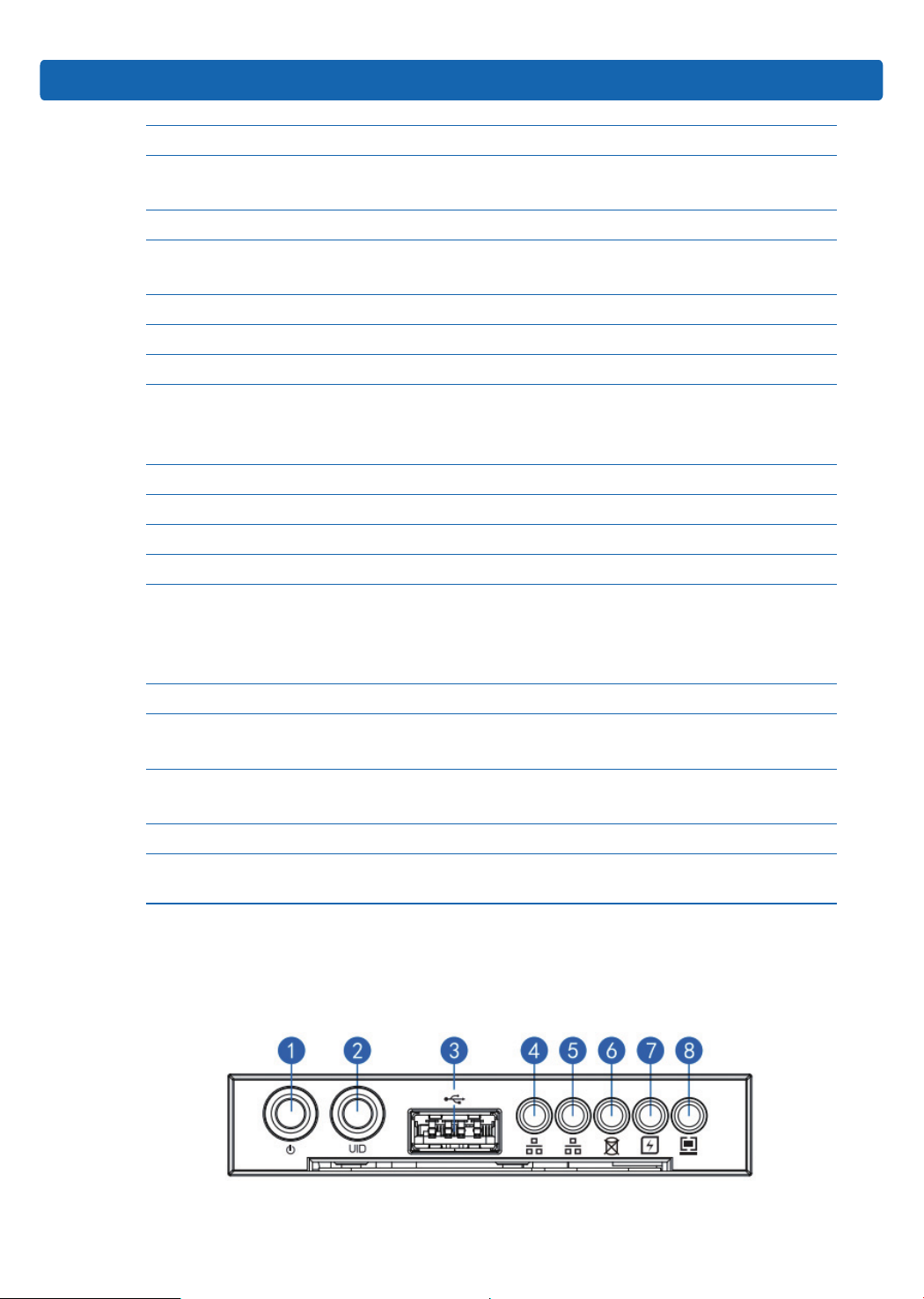
2.3 Front Panel
2.3.1 Buttons and LEDs on the Front Panel
7
No. Name
1 Server switch button
2 ID light and button
3 USB interface
4 NI0 status LED
5 NI1 status LED
6 HDD fault LED
7 Power fault LED
8 System fault LED
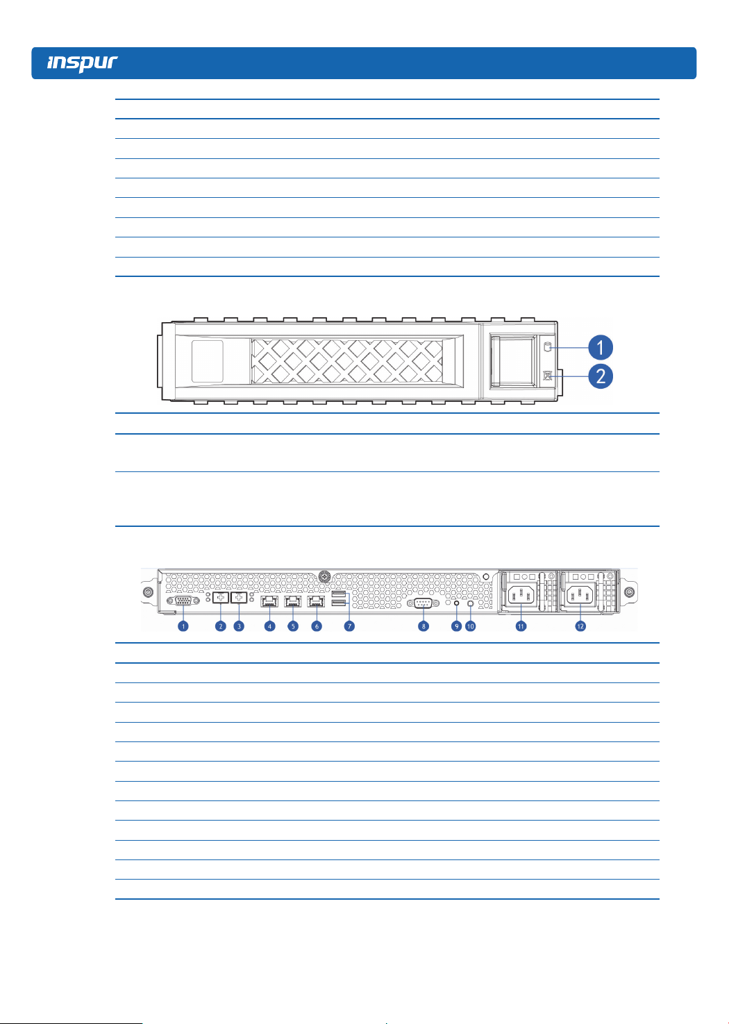
2.3.2 LEDs on the HDD Bracket
No. Name Description
1 HDD activity status LED
2 HDD fault alarm LED
Steady green: normal
Blinking green: HDD is going on read-write activity
Steady red: HDD fails
Steady blue: HDD locating
Steady blue: RAID Rebuilding
2.4 Rear Panel
No. Name
1 VGA interface
2 10 GbE port 1
3 10 GbE port 0
4 IPMI management interface
5 GbE port 0
6 GbE port 1
7 USB port
8 Serial interface
9 BMC reset button
10 UID LED and button
11 PSU1
12 PSU0
Note: according to system settings, the external 10 Gigabit NIC has a higher priority
than Gigabit NIC.
8
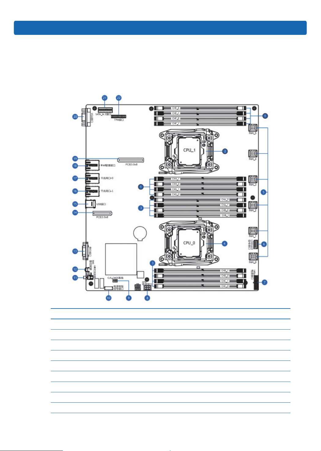
For example: if the server is congured with an external dual-port 10 Gigabit NIC,
the priority is 10 GbE port0> 10 GbE port1> GbE port0> GbE port1.
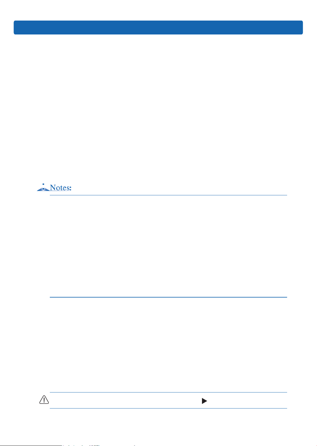
2.5 Motherboard Layout
Product Specications
No. Name
1 DIMMs (corresponding to CPU1)
2 CPU1
3 DIMMs (corresponding to CPU0)
4 CPU0
5 System fan interface (6)
6 Linkboard signal interface
7 14pin power interface
8 6pin power interface
9 CLR_CMOS jumper
9

No. Name
10 Power backplane signal interface
11 UID LED and button
12 BMC Reset button
13 Serial interface
14 PCIE3.0 X8 slots
15 USB port (2)
16 GbE port 1
17 GbE port 0
18 IPMI management port
19 PCIE3.0 X8 slots
20 VGA interface
21 SATA_M.2 interface
22 TPM interface
2.6 CLR_CMOS Jumper Introductions
See [2. 5 Motherboard Layout] for jumper positions.
Jumper No. Name Jumper Functions
CLR_CMOS CMOS clear jumper
Short-circuit pin1-2, normal status; short-circuit
pin 2-3, clear CMOS.
Note:
It is required to shut down the system, as well as disconnect power supply during
CMOS clearing, keep for 5 seconds after short-circuiting Pin2-3; then short-circuit
Pin1 and Pin2 of CLR_CMOS jumper (the default status) with a jumper cap, to
restore to its original status.
10
3 BIOS Setup
This chapter introduces how to congure BIOS. All operations described in this
section are only limited to operators or administrators with system maintenance
qualication.
BIOS is a basic input and output system. The system parameters and hardware
parameters can be adjusted through special setup procedure. BIOS has a great
impact on the system booting and running, setting parameters improperly may cause
conicts among hardware resources, or degrade the system running performance.
Hence understanding the BIOS setup is signicant to the conguration of your
server. If no especial requirement, you are suggested to use the default value and
not alter the parameters arbitrarily.
1. Before changing the BIOS setup, please record the corresponding original setup.
BIOS Setup
Hence when there are operating problems in the system due to the option altered,
the setup can revert to the previous state.
2. Ordinarily the factory default settings are the optimal settings. Don’t try to alter the
parameters before you understand their denotations.
3. The common settings are introduced in detail in this chapter. The less referred
options during using are simply explained or not.
4. The BIOS content varies according to different congurations of the products;
hence the detailed introduction is elided.
3.1 System BIOS Setup Methods
Power on the server, system starts to boot, when the following content appears
below Inspur logo on the screen:
“Press <DEL> to SETUP or <TAB> to POST or <F12> to PXE Boot.”, press [DEL]
button; when “Entering Setup...” appears in the lower right corner, it will enter system
BIOS conguration later, and you could select options in BIOS main menu using
arrow buttons to enter sub-menu.
Note: Options in grey are not available. Options with symbol “ ” have a sub-menu.
11
Control key instruction table
Press Key Function
<Esc> Exit or return from sub-menu to main menu
<←> or <←> Select a menu
<←> or <←> Move the cursor up or down
<Home> or <End> Move the cursor to the top or bottom of the screen
<+> or <->
<F1> Help
<F2> Restore to the last conguration
<F9> Restore to default conguration
<F10> Save and exit
<Enter> Execute commands or select a sub-menu
3.2 BIOS Settings
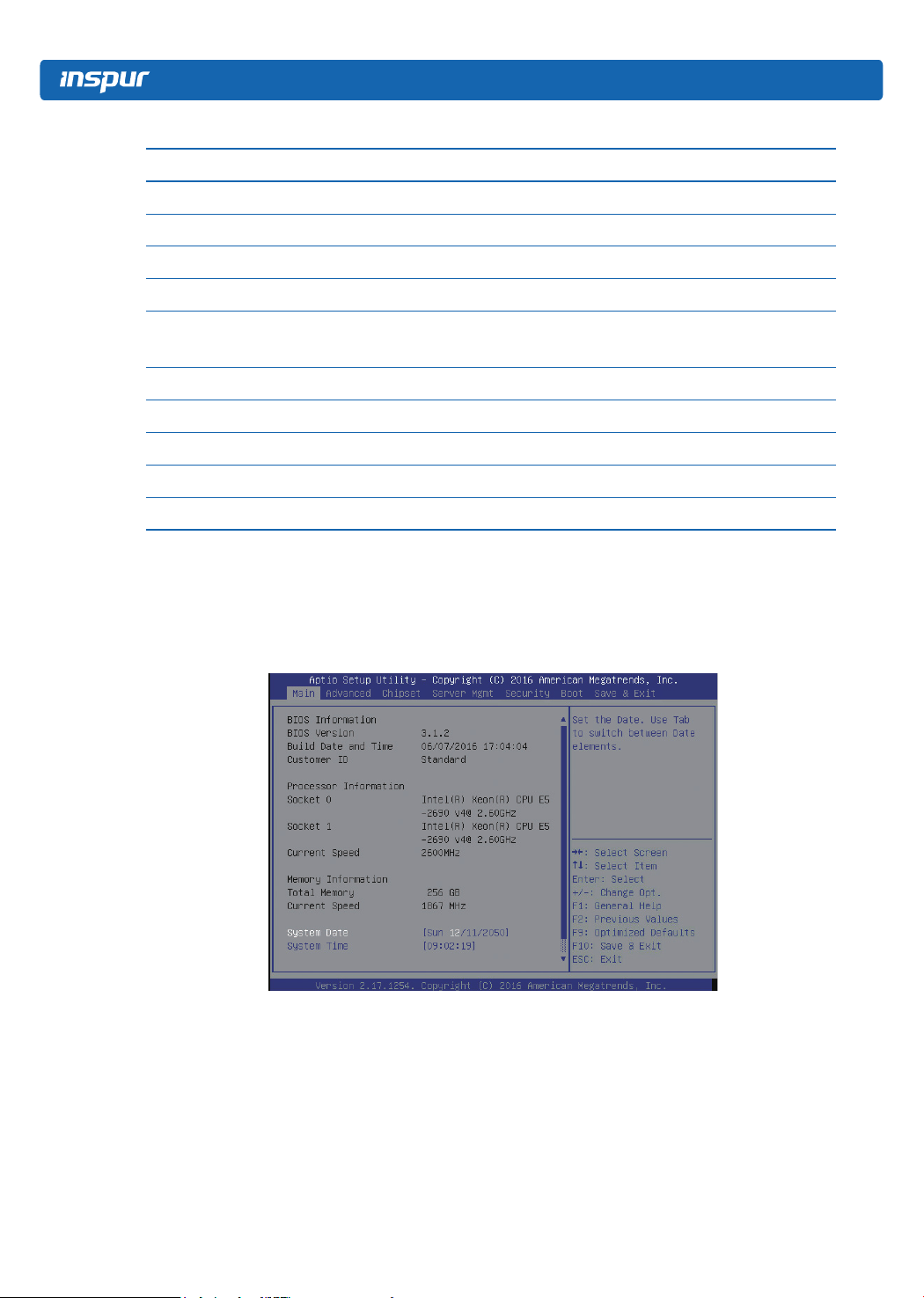
3.2.1 Main Menu
Select the previous or next numerical value or setting of the
current one
12
Main Interface Instruction Table
Interface Parameters Function Des cription
BIOS Information BIOS information
BIOS Version BIOS version information
Build Date and Time BIOS build date and time
Customer ID Customer ID
Processor Information Processor information
Socket 0 CPU0 model information
Socket 1 CPU1 model information
Current Speed CPU current speed
Memory Information Memory information
Total Memory Memory total memory
Current Speed Memory current speed
Display and set system date
Use <Tab> or <Enter> to switch between options of the
System Date
system date and time, directly input the number or use +/keys to change the value (press + key once, the value will
increase by 1, press - key once, the value will decrease by 1)
BIOS Setup
System Time
3.2.2 Advanced Menu
Display and set system time
Use <Tab> or <Enter> to switch between options of the
system date and time, directly input the number or use +/keys to change the value (press + key once, the value will
increase by 1, press - key once, the value will decrease by 1)
13
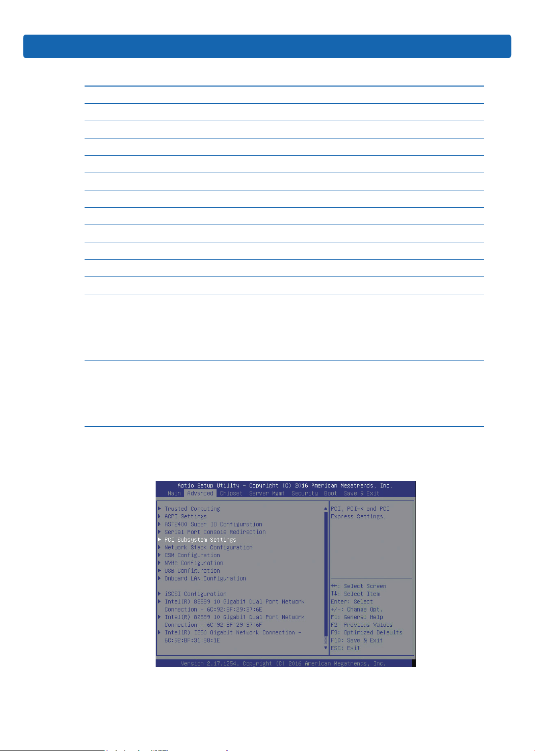
Advanced Interface Instruction Table
Interface Parameters Function Description
Trusted Computing Trusted computing conguration
ACPI Settings
AST2400 Super IO Conguration AST2400 I/O chip parameter conguration
Serial Port Console Redirection Serial port console redirection settings
PCI Subsystem Settings PCI subsystem settings
Network Stack Conguration Network stack conguration
CSM Conguration CMS conguration
NVMe Conguration NVMe conguration
USB Conguration USB conguration
Onboard LAN Conguration Onboard network card conguration
iSCSI Conguration iSCSI conguration
Intel® I350 Gigabit Network
Connection
Advanced conguration and power interface
settings
Intel® I350 GbE NIC connection settings
3.2.2.1 Trusted Computing
14
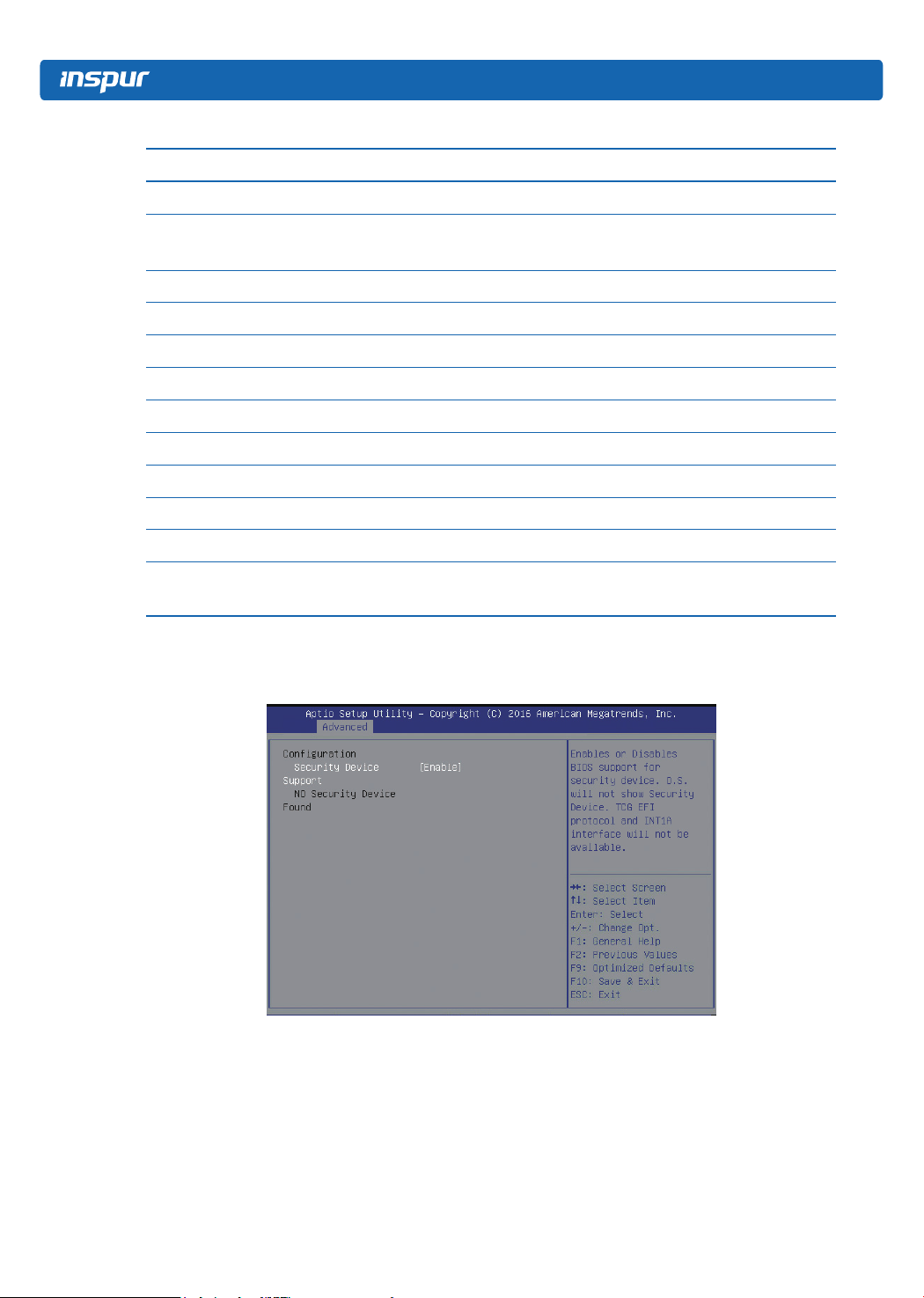
Trusted Computing Interface Instruction Table
Interface Parameters Function Description
Security device support on/off settings,
option parameters:
Enabled
Disabled
Security Device Support
BIOS supports TPM TCG version 1.2/2.0.
BIOS supports TPM module through TPM
software binding, if the software binding
validation fails, BIOS will record the error to
the SEL.
3.2.2.2 ACPI Settings
BIOS Setup
Default
Enabled
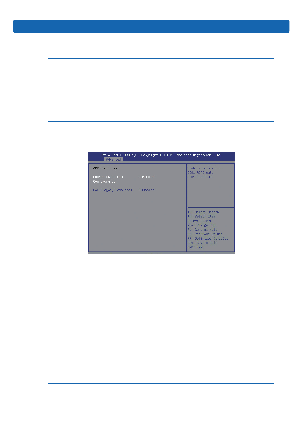
Advanced Interface Instruction Table
Interface Parameters Function Description
ACPI auto conguration on/off settings, option
parameters:
Enable ACPI
Auto Conguration
Lock Legacy Resources
Enabled
Disabled
If enabled, the Lock Legacy Resources will be
hidden, and manual modication is not allowed.
Lock legacy resources on/off settings, option
parameters:
Enabled
Disabled
If enabled, OS will lock the device’s legacy
resources.
Default
Disabled
Disabled
15
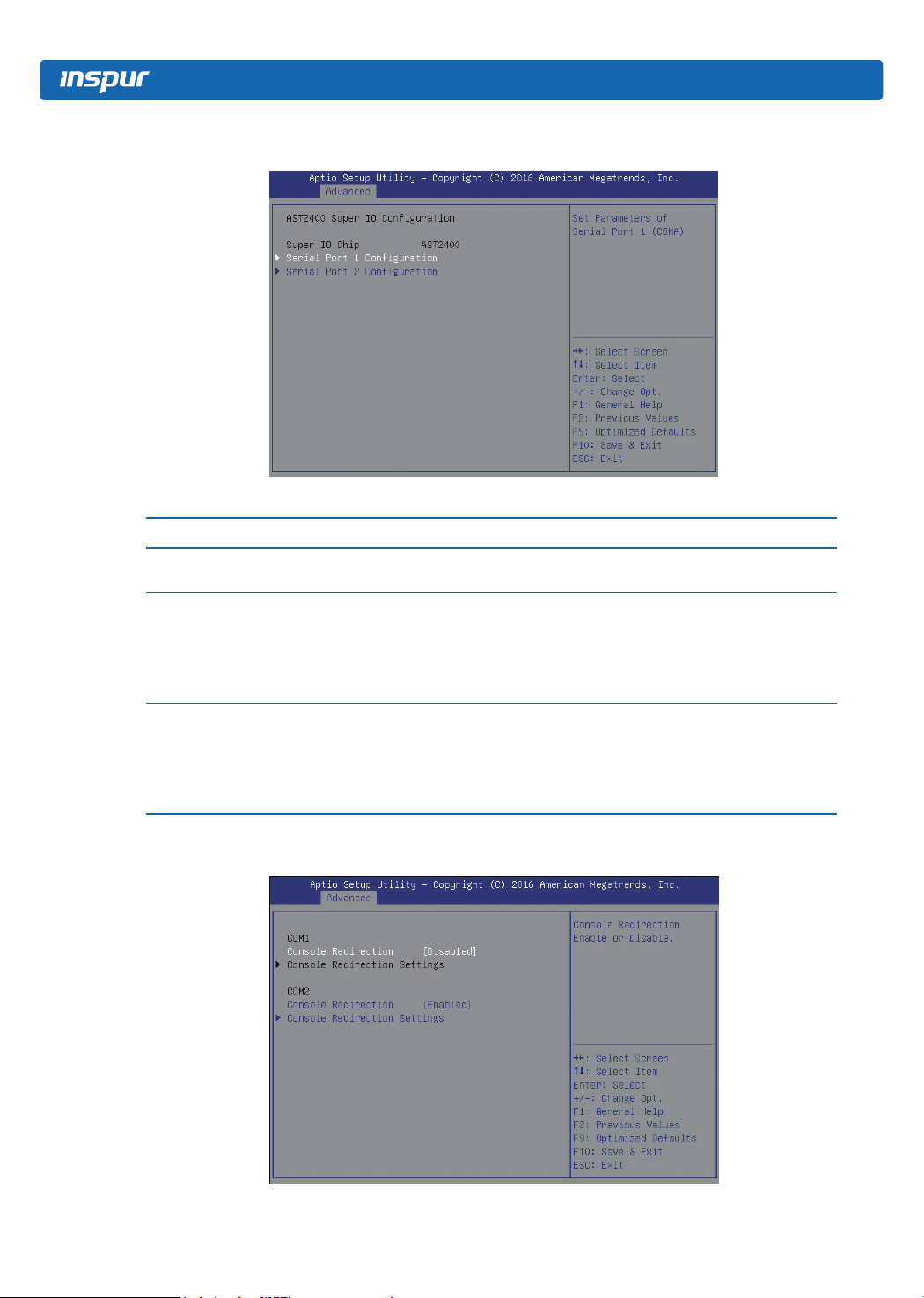
3.2.2.3 AST2400 Super IO Configuration
AST2400 Super IO Conguration Interface Instruction Table
Interface Parameters Function Description
Super IO Chip
Serial Port 1 Conguration
Serial Port 2 Conguration
Display the super I/O chip that the motherboard uses
currently
Serial port 1 conguration, the conguration interface
provides this serial port on/off control and resource
adjustment functions. The resource adjustment function
can manually adjust the IO PORT and IRQ number that
COM PORT uses.
Serial port 2 conguration, the conguration interface
provides this serial port on/off control and resource
adjustment functions. The resource adjustment function
can manually adjust the IO PORT and IRQ number that
COM PORT uses.
3.2.2.4 Serial Port Console Redirection
16

Serial Port Console Redirection Interface Instruction Table
Interface Parameters Function Description
Console redirection on/off settings, option
Console Redirection
Console Redirection Settings Console redirection parameter settings
parameters : Enabled
Disabled
3.2.2.4.1 Console Redirection Settings
BIOS Setup
Default
Disabled
--
When the Console Redirection option is set to [Enabled], the Console Redirection
Settings menu will appear.
Console Redirection Settings Interface Introduction
Interface Parameters Function Description Default
Terminal type settings, option parameters:
VT100
Terminal Type
Bits per second
VT100+
VT-UTF8
ANSI
Bits per second settings, option parameters:
9600
19200
38400
57600
115200
ANSI
115200
17

Data Bits
Parity
Stop Bits
Flow Control
Data bits width settings, option parameters:
7
8
Parity settings, option parameters:
None (no parity)
Even (even parity)
Odd (odd parity)
Mark (odd-even check)
Space (memory parity check)
Stop bits settings, option parameters:
1
2
Flow control settings, option parameters:
None
Hardware RTS/CTS
8
None
1
None
VT-UTF8 Combo Key
Support
VT-UTF8 combo key support settings Enabled
Recorder Mode Recorder mode on/off settings Disabled
Resolution 100×31
Extension terminal resolution 100×31 on/off
settings
Disabled
Legacy OS redirection resolution settings,
Legacy OS Redirection
Resolution
option parameters:
80×24
80×24
80×25
Putty function keys and keyboard settings,
option parameters:
VT100
Putty KeyPad
LINUX
XTERMR6
VT100
SCO
ESCN
VT400
Redirection settings after BIOS post, option
Redirection After BIOS
POST
parameters:
Always Enabled
Always
Enabled
BootLoader
18
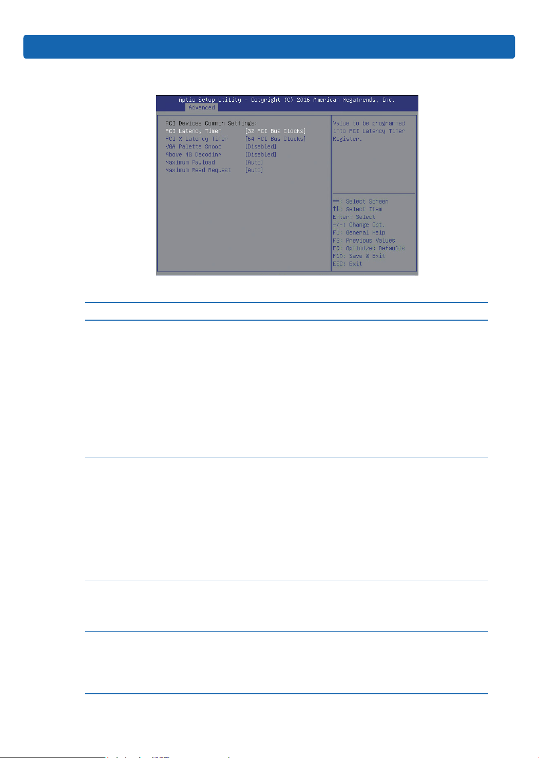
3.2.2.5 PCI Subsystem Settings
PCI Subsystem Settings Interface Instruction Table
Interface Parameters Function Description
PCI device latency timer settings, this is used
to set the time that each PCI device can
occupy the bus, option parameters:
32 PCI Bus Clocks
64 PCI Bus Clocks
PCI Latency Timer
PCI-X Latency Timer
VGA Palette Snoop
Above 4G Decoding
96 PCI Bus Clocks
128 PCI Bus Clocks
160 PCI Bus Clocks
192 PCI Bus Clocks
224 PCI Bus Clocks
248 PCI Bus Clocks
PCI-X device latency timer settings, option
parameters:
32 PCI Bus Clocks
64 PCI Bus Clocks
96 PCI Bus Clocks
128 PCI Bus Clocks
160 PCI Bus Clocks
192 PCI Bus Clocks
224 PCI Bus Clocks
248 PCI Bus Clocks
VGA palette snoop on/off settings, option
parameters:
Enabled
Disabled
4G above memory access control on/off
settings, option parameters:
Enabled
Disabled
Enable or disable above 4G decoding function
BIOS Setup
Default
32 PCI Bus
Clocks
64 PCI Bus
Clocks
Disabled
Disabled
19
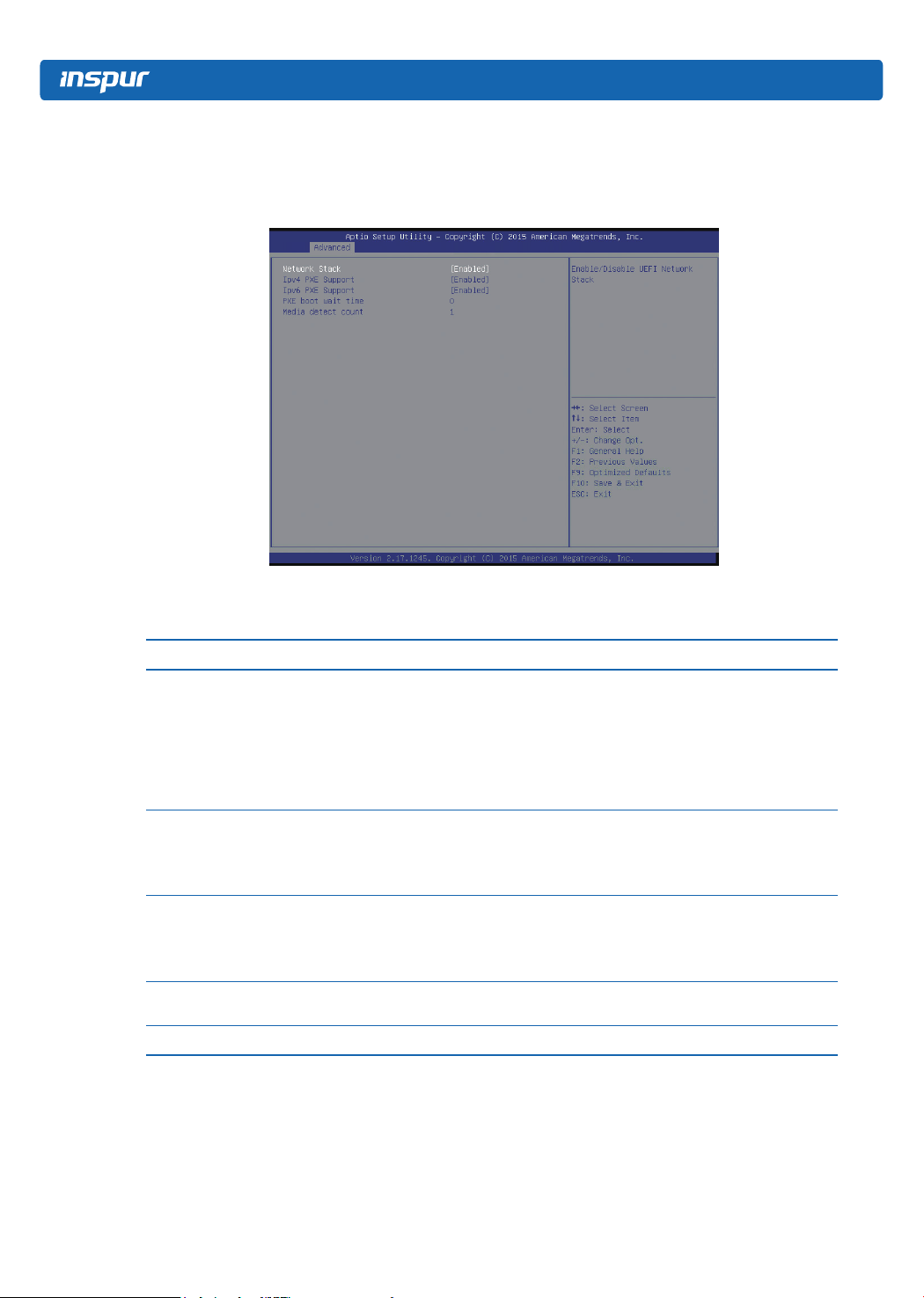
3.2.2.6 Network Stack Configuration
Network Stack Conguration interface is used to set the related options of UEFI pre-
boot network.
Network Stack Conguration Interface Instruction Table
Interface Parameters Function Description
Network stack on/off settings, option parameters:
Enabled
Network Stack
IPv4 PXE Support
IPv6 PXE Support
PXE boot wait time
Media detect count Set PXE media detect count
Disabled
The following options are controlled by this option,
only this option is enabled, the following options will
be displayed and settable.
IPv4 PXE support on/off settings, option
parameters:
Enabled
Disabled
IPv6 PXE support on/off settings, option
parameters:
Enabled
Disabled
Set wait time, pressing ESC key can suspend PXE
boot.
Default
Disabled
Enabled
Enabled
0
1
3.2.2.7 CSM Configuration
CSM Conguration interface is used to set the related options of compatible module.
20
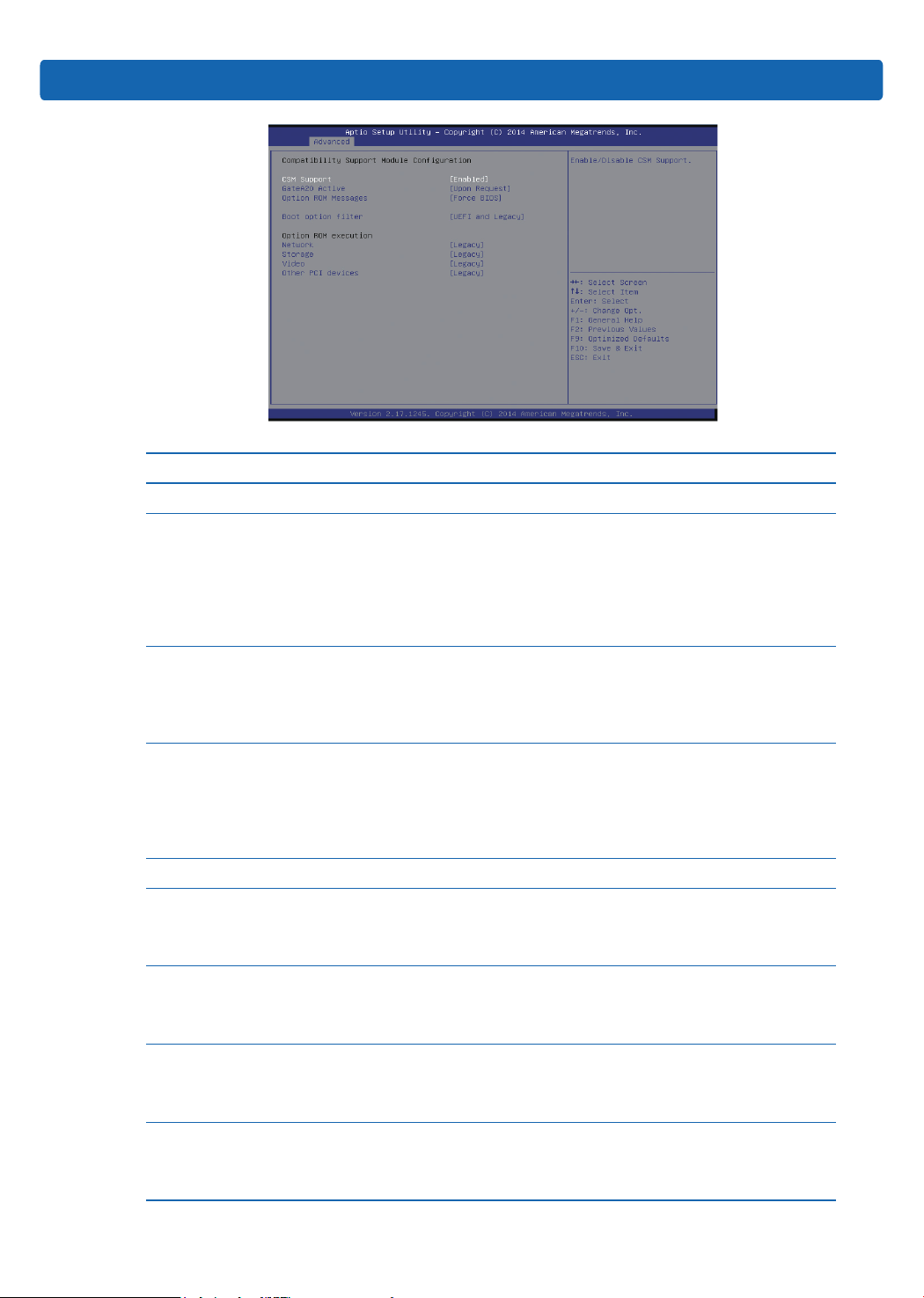
CSM Conguration Interface Instruction Table
Interface Parameters Function Description
CSM Support CSM support on/off settings
A20 address wire control mode settings,
option parameters:
Upon Request
GateA20 Active
Option Rom Messages
Boot option lter
Option ROM execution Option Rom execution mode
Network
Storage
Video
Other PCI devices
Always
A20 is an address wire, which can control the
system how to access memory spaces that
are more than 1MB.
Option Rom messages display mode settings,
option parameters:
Force BIOS: forced display BIOS information
Keep Current: keep current state
Option Rom: no information displayed
Boot option lter settings, to control Legal
and UEFI Option Rom’s boot strategy, option
parameters:
UEFI and Legacy
UEFI only
Legacy only
NIC Option Rom execution mode settings,
option parameters:
Legacy
UEFI
Storage device Option Rom execution mode
settings, option parameters:
Legacy
UEFI
Video device Option Rom execution mode
settings, option parameters:
Legacy
UEFI
Other PCI devices Option Rom execution
mode settings, option parameters:
Legacy
UEFI
BIOS Setup
Default
Enabled
Upon Request
Force BIOS
UEFI and
Legacy
---
Legacy
Legacy
Legacy
Legacy
21
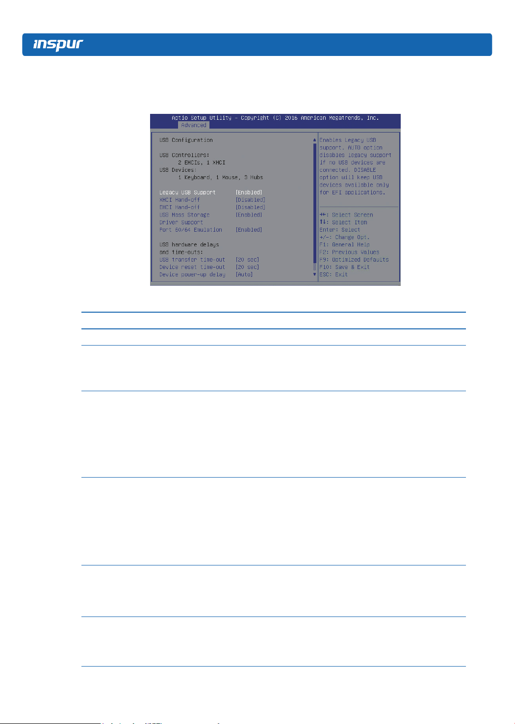
3.2.2.8 USB Configuration
USB Conguration interface is used to set USB related options.
USB Interface Instruction Table
Interface Parameters Function Description
USB Devices Current USB devices information
Legacy USB support on/off settings, option
Legacy USB Support
XHCI Hand-off
EHCI Hand-off
USB Mass Storage
Driver Support
Port 60/64 Emulation
parameters:
Enabled
Disabled
Enable or disable XHCI hand-off function, option
parameters:
Enabled
Disabled
For the operating systems that do not support
XHCI (USB3.0) function, enabling XHCI hand-off
function can realize the support for XHCI.
Enable or disable EHCI hand-off function, option
parameters:
Enabled
Disabled
For the operating systems that do not support
EHCI (USB2.0) function, enabling EHCI hand-off
function can realize the support for EHCI.
USB mass storage driver support on/off settings,
option parameters:
Enabled
Disabled
USB port 60/64 emulation on/off settings, option
parameters:
Enabled
Disabled
Default
--
Enabled
Enabled
Disabled
Enabled
Enabled
22
BIOS Setup
USB Hardware Delay
and Time-outs
USB Transfer Timeout
Device Reset Time-
out
Device Power-up
Delay
Device Power-up
Delay in Seconds
USB hardware delay and time-outs settings --
USB transfer time-out settings, option parameters:
1 sec
5 sec
10 sec
20 sec
USB high-capacity devices reset time-out settings,
option parameters:
10 sec
20 sec
30 sec
40 sec
Device power-up delay settings, option
parameters:
Auto
Manual
Only when the Device power-up delay option is
set to Manual, this option will be displayed and
it is used to set device power-up delay time, set
range is 1-40s.
20 sec
20 sec
Auto
5
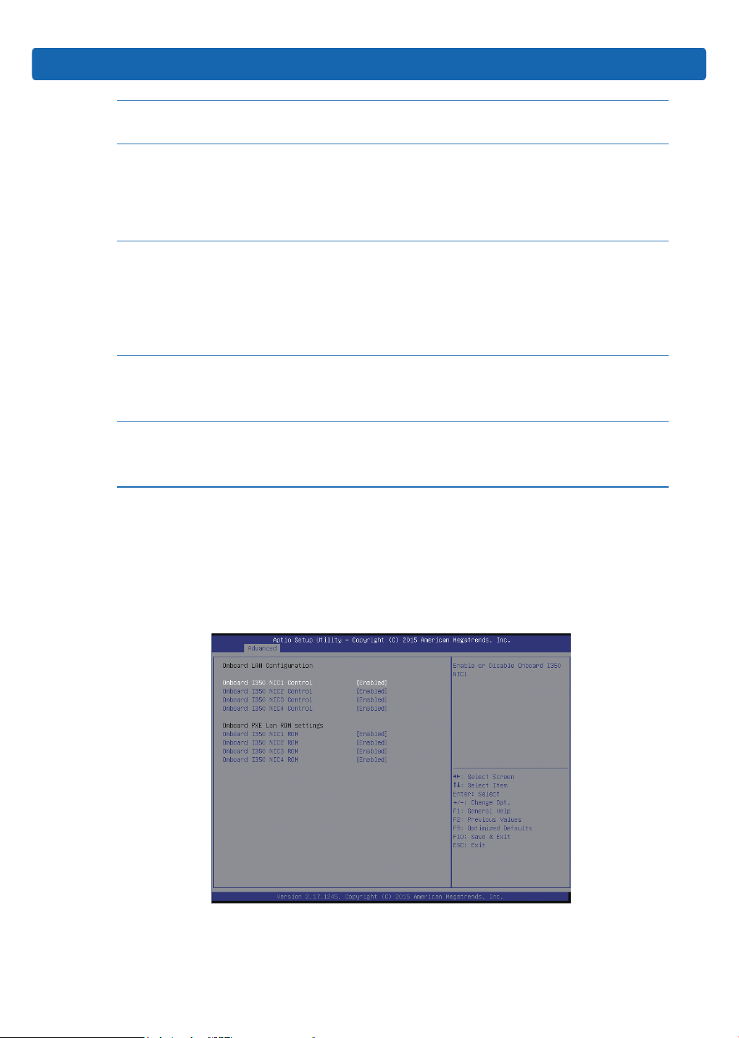
3.2.2.9 Onboard LAN Configuration
Onboard LAN Conguration is used to set the related options of onboard NIC. The
options on this interface vary with different onboard NICs, the specic model will
prevail.
23
Onboard LAN Conguration Interface Instruction Table
Interface Parameters Function Description
Onboard NIC1 on/off settings, option parameters:
Onboard NIC1 Control
Onboard NIC2 Control
Onboard NIC3 Control
Onboard NIC4 Control
Onboard NIC1 ROM
Onboard NIC2 ROM
Onboard NIC3 ROM
Onboard NIC4 ROM
Enabled
Disabled
Onboard NIC2 on/off settings, option parameters:
Enabled
Disabled
Onboard NIC3 on/off settings, option parameters:
Enabled
Disabled
Onboard NIC4 on/off settings, option parameters:
Enabled
Disabled
Onboard NIC1 PXE Oprom on/off settings, option
parameters:
Enabled
Disabled
Onboard NIC2 PXE Oprom on/off settings, option
parameters:
Enabled
Disabled
Onboard NIC3 PXE Oprom on/off settings, option
parameters:
Enabled
Disabled
Onboard NIC4 PXE Oprom on/off settings, option
parameters:
Enabled
Disabled
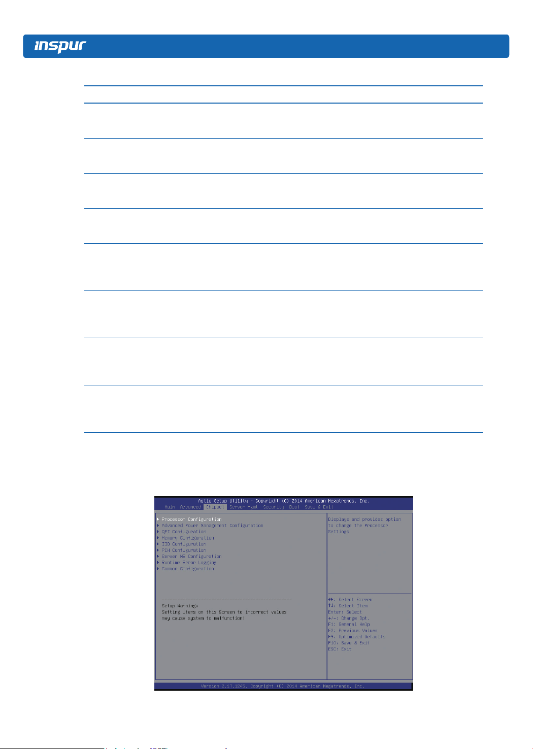
3.2.3 Chipset
Default
Enabled
Enabled
Enabled
Enabled
Enabled
Enabled
Enabled
Enabled
Chipset interface includes the information of CPU, QPI, memory, PCH, ME and other
devices. Users can manage these devices through this interface.
24
Chipset Interface Instruction Table
Interface Parameters Function Description
Processor Conguration Processor conguration
Advanced Power Management Conguration
QPI Conguration QPI conguration
Memory Conguration Memory conguration
IIO Conguration IIO conguration
PCH Conguration PCH conguration
Server ME Conguration Server ME conguration
Runtime Error Logging Runtime error logging conguration
Common Conguration Common options conguration
Advanced power management
conguration
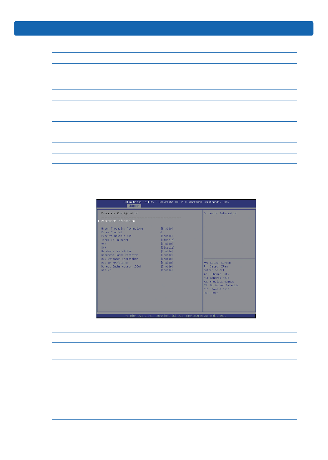
3.2.3.1 Processor Configuration
Processor Conguration is used to set the related options of processor.
BIOS Setup
Processor Conguration Interface Instruction Table
Interface Parameters Function Description Default
Processor
Information
Hyper Threading
Technology
Core Enabled
Processor information submenu, display processor
detailed information.
Hyper threading technology settings, option parameters:
Enabled
Disabled
Number of CPU cores settings, input the number of
CPU cores to be enabled. The default valued is 0,
which means enabling all CPU cores.
--
Enabled
0
25

Execute Disable Bit
Intel TXT Support
VMX
SMX
Hardware Prefetcher
Adjacent Cache
Prefetch
DCU Streamer
Prefetcher
DCU IP Prefectcher
Direct Cache Access
(DCA)
AES-NI
Execute Disable Bit on/off settings, option parameters:
Enabled
Disabled
Intel TXT support on/off settings, option parameters:
Enabled
Disabled
Intel VMX on/off settings, option parameters: Enabled
Disabled
SMX on/off settings, option parameters: Enabled
Disabled
Hardware prefetcher on/off settings, option parameters:
Enabled
Disabled
Before CPU processing instructions or data, it will
prefetch these instructions or data from memory to L2
cache, to shorten the amount of time reading memory
takes, to help eliminate potential bottlenecks, to
improve system performance.
Adjacent cache prefetch on/off settings, option
parameters:
Enabled
Disabled
If this function is enabled, when computer reading
data, it will intelligently consider the adjacent data is
needed as well, and it will prefetch these data during
processing, to speed up the reading process.
DCU streamer prefetcher on/off settings, option
parameters:
Enabled
Disabled
This function can prefetch CPU data to shorten the data
reading time.
DCU IP prefectcher on/off settings, option parameters:
Enabled
Disabled
This function can judge from the history whether there
is data to prefetch, to shorten the data reading time.
Direct cache access on/off settings, option parameters:
Enabled
Disabled
DCA is a system-level driver, it can directly put the data
from IO device into CPU cache to improve the network
IO performance.
AES instruction on/off settings, option parameters:
Enabled
Disabled
This menu is mainly used to control whether CPU
supports AES instructions, which are used to support
fast and secure encryption and decryption.
Enabled
Disabled
Enabled
Disabled
Enabled
Enabled
Enabled
Enabled
Enabled
Enabled
26
 Loading...