

Inspur AS1100H User Manual

Inspur Storage System
AS1100H
User Manual v1.0
Inspur

Dear users of Inspur storage system:
Sincerely thank you for selection of Inspur storage system!
This manual introduces the technical characteristics and system installation, setup and usage
of Inspur storage system, and helps you to particularly understand and expediently use this storage
system.
Please deliver the package of our product to the waste recycling station for recycling, in favor
of pollution prevention and humankind’s benefit.
This manual is the property of Inspur.
This User Manual is not to be copied by any group or person in any manner without the
consent of Inspur. The Inspur reserves the right of revising this manual momentarily.
Any alteration about the content of this manual will not be noticed. We suggest that the user
shall read this manual before using Inspur storage system, so as to avoid any mistake during
operation.
Please forgive any insufficiency in details, point out and give directions for us in time.
Please contact Inspur, if you have any questions or advice about this manual.
Inspur
May. 2014
“Inspur ” is a registered trademark of the Inspur Group Co., Ltd.
Other trademarks belong to other corresponding registered companies.

Statement
Please read the following statement before you use this storage system formally. Only when
you have read this statement hereinafter and agreed the following terms, you can formally use this
storage system. If you have any questions about the following terms, please contact our supplier or
us directly. If you have no questions about these terms and start to use this system, it acquiesces
that you have agreed the following terms.
1. We must call your attention that you must not alter any other parameters in the main board
BIOS of this storage system at any time, except for the parameters which we promote that you can
alter.
2. If there are any hardware problems when you use this storage system, or you wish to
upgrade the hardware, please feed back the detail hardware configuration of your computer to our
Customer Service. Don’t disassemble the storage system case or any hardware components in the
case by yourself.
3. Memory, CPU, board card, BBU, fan, disk tray and hard disk etc. of this storage system
are of special specification; please do not use them with equipment of any other type.
4. When you have any software problems during the application of this storage system, we
hope that you firstly contact the corresponding software supplier and then he will contact us in
favor of communication so as to solve your problem together, especially the software problems
about the database, the installation and running of the network management software or other
networking products.
5. Please read quick installation guide in this manual carefully before installing this storage
system. Inspur is engaged in constantly improving product function and performance, which may
cause part of functions different from description in this manual, but not impact usage, if you have
any doubt on usage, please contact our customer service center.
6. We must call your attention that in the application process, you should pay attention to do
necessary backup of your file.
7. This is a Grade A product, and this product may induce radio jamming. In this case, users
need to adopt feasible measures to the interference.
8. Please carefully read and comply with safety rules in this manual.
9. The copyrights of the markers and names of the software and hardware product referred in
this manual are the property of corresponding companies.
In the above statement, “us” indicates Inspur. Inspur holds the right of final explanation
about the above statement.

Safety Rules
1. The power supply equipment in the system may generate high voltage and dangerous
electrical energy and thus cause personal injury. Please do not dismount the cover of the host or to
dismount and replace any component in the system by yourself, unless otherwise informed by
Inspur, only maintenance technicians trained by Inspur have the right to disassemble the cover of
the host, dismount and replace the internal components.
2. Please connect the equipment to appropriate power supply, and the power should be
supplied by external power supply which is indicated on the rated input label. To prevent your
equipment from damages caused by momentary spike or plunge of the voltage, please use relevant
voltage stabilizing equipment or uninterruptible power supply equipment.
3. If extended cables are needed, please use the three-core cables matched with correct
earthed plug, and check the ratings of the extended cables to make sure that the sum of rated
current of all products inserted into the extended cables do not exceed 80% of the limits of the
rated currents of the extended cables.
4. Please be sure to use the supplied power supply component, such as power lines, power
socket (if supplied with the equipment) etc. For the safety of equipment and the user, do not
replace randomly power cables or plugs.
5. To prevent electric shock dangers caused by leakage in the system, please make sure that
the power cables of the system and peripheral equipment are correctly connected to the earthed
power socket. Please connect the three-core power line plug to the three-core AC power socket
that is well earthed and easy to access, be sure to use the earthing pin of power lines and do not
use the patch plug or the earthing pin unplugged with cables. In case of the earthing conductors
not installed and it is uncertain whether there are appropriate earthing protections, please do not
operate or use the equipment. Contact and consult with the electrician.
6. To avoid short circuit of internal components and fire or electric shock hazards, please do
not fill any object into the open pores of the system.
7. Please place the system far away from the cooling plate and at the place with heat sources,
and be sure not to block the air vents.
8. Be sure not to scatter food or liquid in the system or on other components, and do not use
the product in humid and dusty environment.
9. The replacement of batteries with those of another models may cause explosion. When
replacement of batteries is required, please consult first the manufacturer and choose batteries of
the same or a similar model recommended by the manufacturer. Do not dismount, extrude and
pink the batteries or make the external connection point short circuit, and do not expose them in
the environment over 60°C. Never throw them into fire or water. Please do not try to open or
repair the batteries, and be sure to reasonably deal with the flat batteries and do not put the
exhausted batteries, the circuit boards that may include the batteries and other components with
other wastes. For relevant battery recovery, please contact the local waste recovery and treatment
mechanism.

Contents
Statement........................................................................................................................................... 3
Chapter I Installation Preparations .................................................................................................... 8
1.1 Key terminology ................................................................................................................. 8
1.2 Necessary parts ................................................................................................................... 8
1.3 Hardware overview ............................................................................................................. 9
Chapter II Install HBA Card ........................................................................................................... 12
2.1 Key terminology ............................................................................................................... 12
2.2 Notes for installing HBA cards ......................................................................................... 12
2.3 Install HBA card................................................................................................................ 12
Chapter III Configure Switches ...................................................................................................... 13
Chapter IV Quick Installation Guide .............................................................................................. 14
4.1 Cabinet preparation ........................................................................................................... 14
4.2 Storage system guide rail suite .......................................................................................... 14
4.3 Install guide rail to cabinet ................................................................................................ 15
4.4 Install the equipment into cabinet ..................................................................................... 17
Chapter V Connect Controller and Host ......................................................................................... 19
5.1 Key terminology ............................................................................................................... 19
5.2 Host connection notes ....................................................................................................... 19
5.3 Steps to connect host ......................................................................................................... 20
5.4 Host channel connection topology .................................................................................... 20
5.4.1 Direct connection topology .................................................................................... 20
5.4.2 Switch connection topology ................................................................................... 21
5.4.3 Mixed connection topology .................................................................................... 21
5.5 Management method topology .......................................................................................... 22
5.5.1 In-band management .............................................................................................. 22
5.5.2 Out-of-band management ....................................................................................... 23
Chapter VI Connect Extension Cabinet .......................................................................................... 24
6.1 Key terminology ............................................................................................................... 24
6.2 Connection notes ............................................................................................................... 24
6.2.1 Disk channels ......................................................................................................... 24
6.2.2 Extension cabinet connection notes ....................................................................... 24
6.3 Extension cabinet connection steps ................................................................................... 25
6.4 Disk array extension illustration ....................................................................................... 25
Chapter VII Connect Power Supply ................................................................................................ 28
7.1 Power line connection notes.............................................................................................. 28
7.2 Power line connection steps .............................................................................................. 28
Chapter VIII System Power-on and Check ..................................................................................... 29
8.1 System power-on steps ...................................................................................................... 29

8.2 Disk array indicator description ........................................................................................ 29
8.3 Part repair indicator ........................................................................................................... 30
Chapter IX Install Storage Management Software ......................................................................... 31
9.1 Key terminology ............................................................................................................... 31
9.2 Installation introduction .................................................................................................... 31
9.3 Operating system special introduction .............................................................................. 31
9.4 Installation environment requirement ............................................................................... 32
9.5 Disk space requirement ..................................................................................................... 33
9.6 Software installation steps................................................................................................. 33
9.7 STRMGR management software module introduction ..................................................... 33
9.8 Software module selection reference ................................................................................ 34
9.9 Install RDAC under Linux ................................................................................................ 34
Chapter X Configure HBA Cards ................................................................................................... 35
10.1 Configure HBA Cards in Windows Server 2003 ............................................................ 35
10.2 Configure HBA Cards in Windows Server 2008............................................................. 35
10.3 Configure HBA cards in Linux ....................................................................................... 35
Chapter XI Start Management Software ......................................................................................... 36
11.1 Management software startup ......................................................................................... 36
11.2 Enterprise Management Window (EMW) and Array Management Window (AMW) .... 36
Chapter XII Add a Storage Array ................................................................................................... 38
Chapter XIII Name the Storage Array ............................................................................................ 39
13.1 Naming notes .................................................................................................................. 39
13.2 Naming steps ................................................................................................................... 39
Chapter XIV Troubleshooting......................................................................................................... 40
Chapter XV Configure Controllers Manually ................................................................................. 41
15.1 Configuration notes ......................................................................................................... 41
15.2 Configuration steps ......................................................................................................... 41
Chapter XVI Set a Password ........................................................................................................... 43
16.1 Password setting notes .................................................................................................... 43
16.2 Password setting steps ..................................................................................................... 43
Chapter XVII Configure Email and SNMP Alarm ......................................................................... 44
17.1 Configuration notes ......................................................................................................... 44
17.2 Alert notification configuration steps .............................................................................. 44
17.3 Mail server tab ................................................................................................................ 44
17.4 Email tab ......................................................................................................................... 44
17.5 SNMP tab ........................................................................................................................ 45
Chapter XVIII Cache Setting .......................................................................................................... 46
18.1 Cache setting notes.......................................................................................................... 46
18.2 Modify cache setting ....................................................................................................... 46

18.3 Modify volume cache setting .......................................................................................... 47
Chapter XIX Add a Host ................................................................................................................. 48
19.1 Key terminology ............................................................................................................. 48
19.2 Adding host notes ............................................................................................................ 48
19.3 Define a host group ......................................................................................................... 48
19.4 Storage partition usage notes........................................................................................... 48
19.5 Adding a host steps ......................................................................................................... 50
Chapter XX Configure Storage System .......................................................................................... 51
20.1 Key terminology ............................................................................................................. 51
20.2 Capacity allocating notes ................................................................................................ 51
20.3 Volume group, DDP and volume creating notes ............................................................. 52
20.4 Host to volume mapping and storage partition notes ...................................................... 52
20.5 Hot spare disk usage notes .............................................................................................. 52
20.6 Storage configuration steps ............................................................................................. 52
Hazardous Substances or Elements Name and Content Table – Storage System ........................... 54

Chapter I Installation Preparations
This chapter mainly describes preparations for installing AS1100H storage system.
1.1 Key terminology
Controller main cabinet
Controller main cabinet contains one or two controllers, power modules and fan modules etc.,
controller main cabinet provides interfaces for storage disk arrays and the host, and 12 hard disks
could be inserted into controller main cabinet.
Extension cabinet
Hard disks could be installed into extension cabinet, not including controller, it contains
environment services monitor (ESM), power module and fan module etc. Extension cabinet is
usually connected to the back of controller main cabinet, and could be connected to other
extension cabinets, so as to meet expansion of disk array volume.
SFP
SFP is a kind of equipment communicating with fiber optical equipment, SFP could be used
on HBA cards and controllers.
1.2 Necessary parts
Hardware
Cabinet Make sure cabinet complies with AS1100H specification, and
power supply could provide sufficient power.
Guide rail
support and
screws
Used for installation of storage AS1100H.
Cables
Power lines Power lines installed together with storage could be used to
connect an external power supply, if your cabinet is equipped
with special power lines, these could be replaced.
Optical fiber
lines
Use optical fiber lines to connect storage arrays and the host or
optical switches.
Ethernet cables Used to connect storage arrays to carry out out-of-band
management.
Other tools
Screwdrivers One slotted screwdriver and one Phillips screwdriver.
Antistatic
equipment
To avoid static damages.
Label paper Used to mark positions.
1.3 Hardware overview
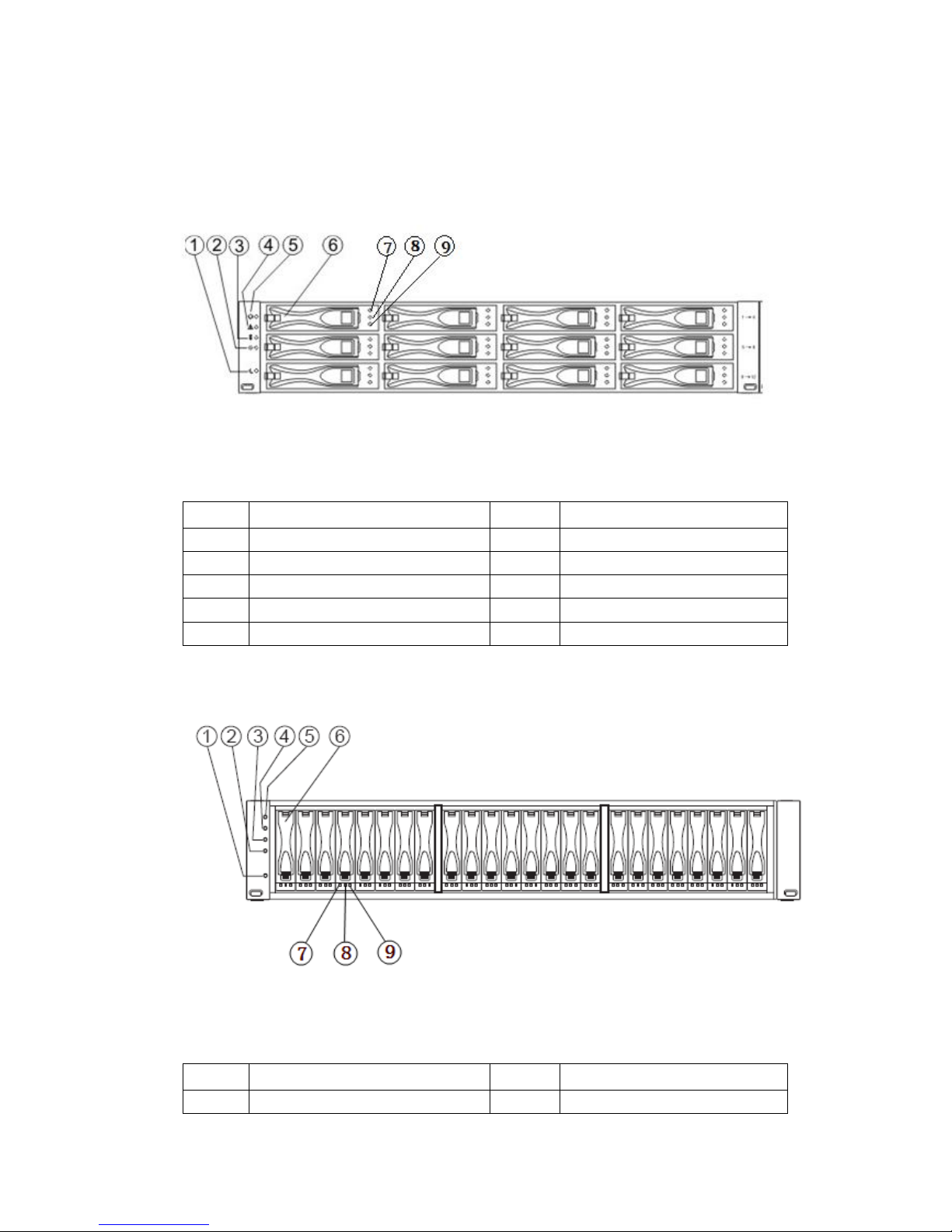
Front view of AS1100H (12 hard disks configuration) is as shown in the following Figure
1-1.
Figure 1-1 Front View of AS1100H
Hard disk sequence, the first row (1-4), the second row (5-8), the third row (9-12).
Number
Name Number
Name
1 Backup power indicator 6 Disk driver module
2 Power indicator 7 Maintainable
3 Temperature alarm indicator 8 Disk fault indicator
4 Service operation indicator 9 Disk power indicator
5 Position indicator
Front view of AS1100H (24 hard disks configuration)is as shown in the following Figure 1-2.
Figure 1-2 Front View of AS1100H
Hard disk sequence, 1 to 24.
Number
Name Number
Name
1 Backup power indicator 6 Disk drive module
2 Power indicator 7 Maintainable
3 Temperature alarm indicator 8 Disk fault indicator
4 Service operation indicator 9 Disk power indicator
5 Position indicator
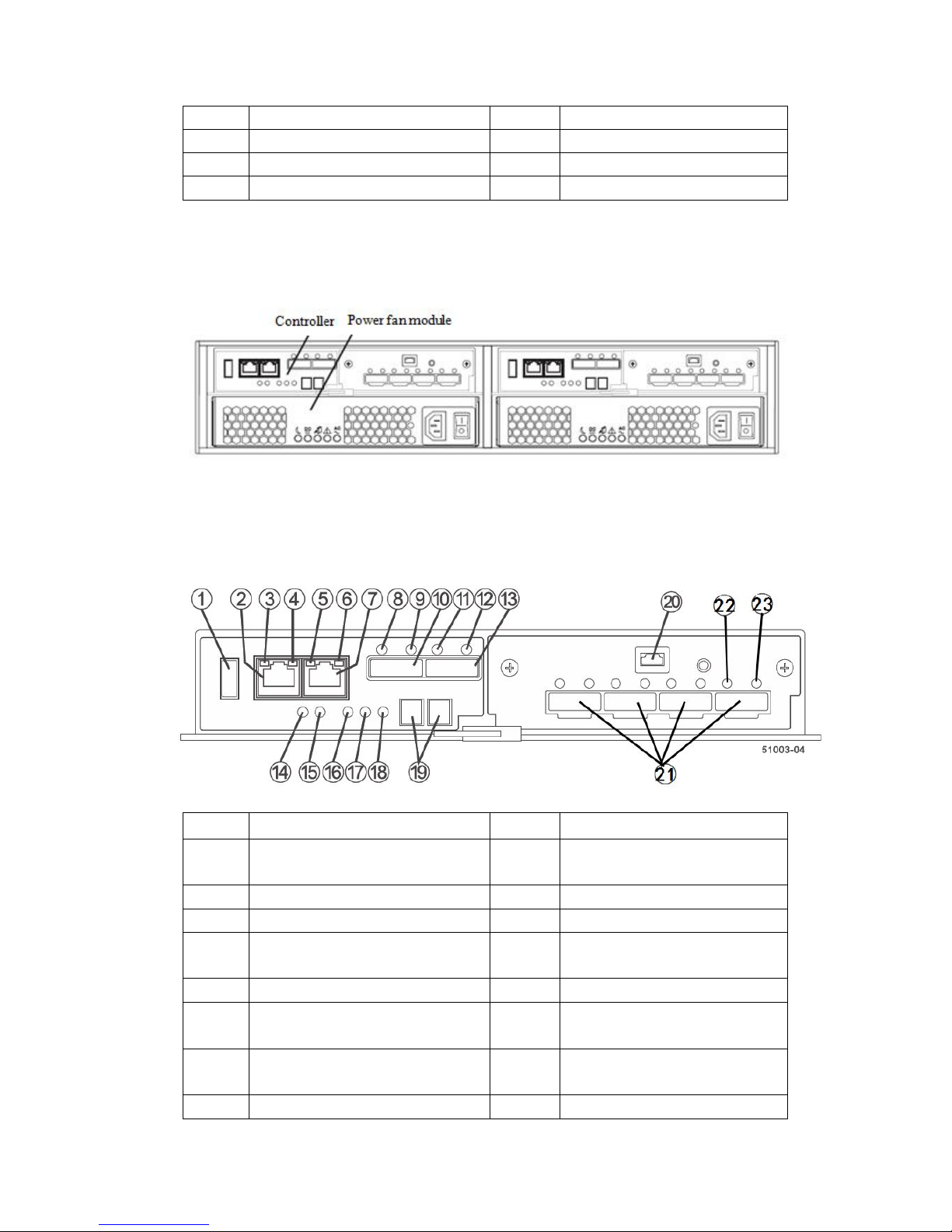
Rear view of AS1100H (configured with SAS HIC card) is as shown in the following Figure
1-3:
Figure 1-3 Rear View of AS1100H
AS1100H controller (configured with SAS HIC card) is as shown in the following figure:
Number
Name Number
Name
1 USB interface 13 SAS (SFF-8088) extension
interface 2
2 Network interface 1 14 Backup power indicator
3 Network connection fault indicator 15 DC power indicator
4 Network interface connection
indicator
16 Power fan module permit
maintenance indicator
5 Network connection fault indicator 17 Power fan module alarm indicator
6 Network interface connection
indicator
18 AC power indicator
7 Network interface 2 19 DC power indicator
seven-segment digital display
8 SAS extension connection fault 20 Serial interface

indicator
9 SAS extension connection indicator
21 HIC card host channel interface
10 SAS (SFF-8088) extension interface
1
22 SAS host channel connection
fault indicator
11 SAS extension connection fault
indicator
23 SAS host channel connection
indicator
12 SAS extension connection indicator
The rear view of AS1100H may be different on host interface types because of different HIC
cards.

Chapter II Install HBA Card
2.1 Key terminology
HBA card (host bus adapter)
Host bus adapter, physical card installed on the host, providing data IO transmission between
the host and storage controller.
Host port of HBA card
Physical and electrical interface in the host for HBA card to connect storage, most HBA cards
have one or two host ports. Each HBA card has a unique WWID number, and host port of each
HBA card has a unique WWID number.
2.2 Notes for installing HBA cards
Host channel of AS1100H is FC, and FC HBA card needs to be used on the host, while FC
switch needs to be used on switch, and the speed shall match either.
In order to provide the maximum hardware redundancy, 2 HBA cards need to be installed on
one host, and doubleport HAB card provides 2 host ports, rather than redundancy feature.
In order to achieve the maximum performance, it is better to use 16Gb storage host channel
with a 16Gb HBA card, if an 8Gb HBA card is used, data transmission rate will be kept at 8Gb.
When host operating system is VMware, mixed connection will not be supported in one
partition.
Windows operating system does not support mixed connection in one partition, when a host
uses multiple partitions to connect the same storage array, no repeated lun number shall be used.
Mixed connection from a host to a storage array is not supported by other operating systems.
2.3 Install HBA card
1. Make sure the HAB card in use is compatible with storage.
2. Install HBA cards according to documents provided by manufacturer.
3. Restart the host.
4. During self-checking of the host, pay attention to prompt messages about entering HBA
card BIOS, enter HBA card BIOS according to these messages.
5. Record the following information: Host name, HBA card on the host, host port WWID on
each HBA card.

Chapter III Configure Switches
This chapter briefly introduces the configuration and use of switches.
1. Make sure the switch in use is compatible with this storage array.
2. Install the switch according to documents provided by switch manufacturer.
3. Visit website of optical switch manufacturer, obtain the latest Firmware and management
software, and update optical switch Firmware, you may need to shut down the switch to restart.
4. If a Brocade or Cisco optical switch is used, it is required to use configuration management
of the switcher to open IOD (In-Order Delivery) option.
5. According to your needs, you can divide zone of the switch under the direction of engineer.
6. For more instructions, please consult the switch manufacturer.

Chapter IV Quick Installation Guide
This part mainly introduces quick installation of the equipment, according to the following
description, you could complete installation of the equipment in the shortest time, in the safest
way.
Note
Threaten brought by static electricity – Static electricity is a fatal threaten to electronic
equipment, for static electricity may puncture some electronic parts, causing failure of the whole
equipment, and bringing along huge losses unconsciously. So, during operation on equipment,
make sure to carry out electrostatic protection, which will not be noted in the following sections.
4.1 Cabinet preparation
Cabinet leveling: Cabinet must be placed firmly, adjust four legs at the bottom, make the cabinet
be placed on the ground firmly. Meanwhile, dismantle cabinet door and side panel
for guide rail installation.
Cabinet grounding: In order to avoid electric shock risk, it is required to install an earthing device
inside the cabinet. If power line of this equipment is inserted into power socket as
part of the cabinet, proper earthing must be provided for the cabinet. If power line
of storage system is inserted into power socket on the wall, earthing device inside
power socket only provides earthing for this equipment, it is required to provide
proper earthing protection for the cabinet as well as other equipment inside it. It is
suggested that you shall use the cabinet specially designed for Inspur storage system.
If you’re using an Inspur storage cabinet, and all parts inside the cabinet are
grounded, Please do not change any of earthing connections inside the cabinet.
Temperature: If storage equipment is installed inside the cabinet, operating and working
temperature of storage system shall not be lower than 5 , nor higher than 35 .℃ ℃
Ventilation: Cabinet used by storage equipment shall provide sufficient wind flow for front and
rear parts of the system, and shall guarantee a 4100Btu heat discharge per hour,
while above 1m space shall also be kept in front and rear.
4.2 Storage system guide rail suite
Articles contained in guide rail suite for this equipment are as shown in Table 4-1.
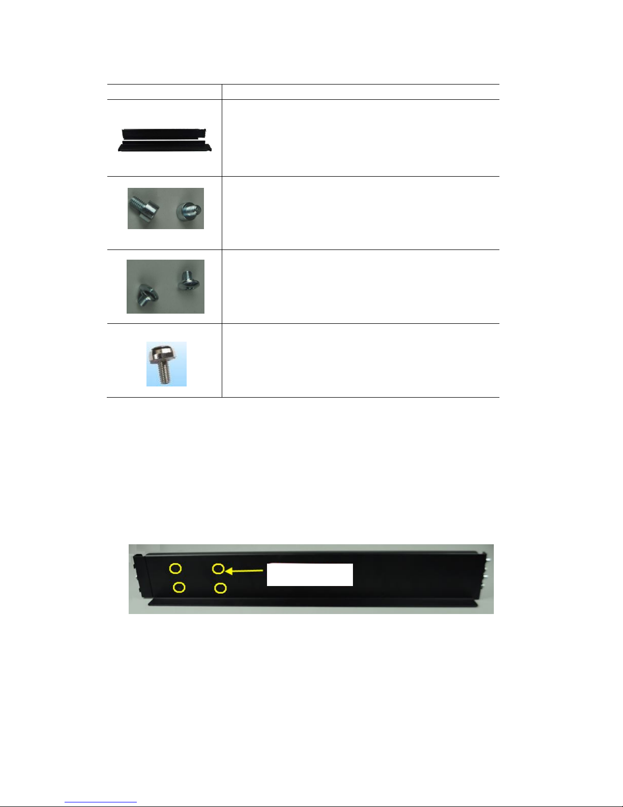
Table 4-1 Guide Rail Suite
Illustration Description
L type guide rail (one piece on left and right)
This guide rail adopts the design of rear-hang, flexible probe
and free of nuts, greatly simplifying installation process.
This guide rail applies to installation of 2U, 3U and 4U
equipment, and can reach a 65kg bearing.
Front position columns (2 for each, 4 in all)
Usually attached to the front rail.
Fix the position column on front rail, install it into the angle
rail hole, to undertake gravity.
Round head screws (M5×6, 2 screws for each, 4 screws in all)
Usually 1 screw is attached to front and rear rail respectively.
During usage, fix guide rail onto angle rail, to fix and
undertake gravity.
Crown screws (M5×16, 1 screws for each, 2 screws in all)
Usually attached to the front rail.
During usage, fix screws onto angle rail, to fix and aovid
falloff.
4.3 Install guide rail to cabinet
1. Length of front and rear rail could extend freely when pulled, in order to guarantee
guide rail bearing, a certain friction is required during extension, otherwise, both front and
rear rails will become too loose; on the contrary, if too tight, front and rail rails will not be
able to extend, it is required to loosen four turnbuckle screws as shown in Figure 4-1
according to situation.
Figure 4-1
2. Extend front and rear guide rails, to make its length equivalent to front and rear
distance of cabinet angle rail.
3. Confirm installation position of the equipment, generally, a height scale is marked
on cabinet angle rail, and introduction will be given in below taking 32U position installation
as an example.
4. On rear guide rail, there’re two connectors, align the lower connector with the
Turnbuckle screw

second hole above the starting point of 32U scale on angle rail, the upper connector with the
second hole above the starting point of 33U scale, insert the connector through the hole, and
then press it down, to connect it to angle rail, now L-shaped part of guide rail shall be leveled
with the starting point of 32U scale, and rear rail fixing holes shall display in the center of the
third hole above the starting point of 32U, as shown in Figure 4-2.
Figure 4-2
5. Adopt guide rail standard configuration of M5×6 round head screws, screw in rear
rail fixing holes, to fix guide rail.
6. Adjust fixing positions of two fixing columns of front guide rail as required, so as to
leave corresponding positions for front fixing holes of the equipment, place guide rail to a
horizontal position, align lower edge with 32U starting point, extend fixing columns into
angle rail fixing holes, and fix them with round head M5×6 screws, as shown in Figure 4-3,
while fixing positions of round head M5×6 screws are also required to be ascertained
according to corresponding positions of front fixing holes of the equipment, so as to avoid.
Rear rail fixing hole
Keep level
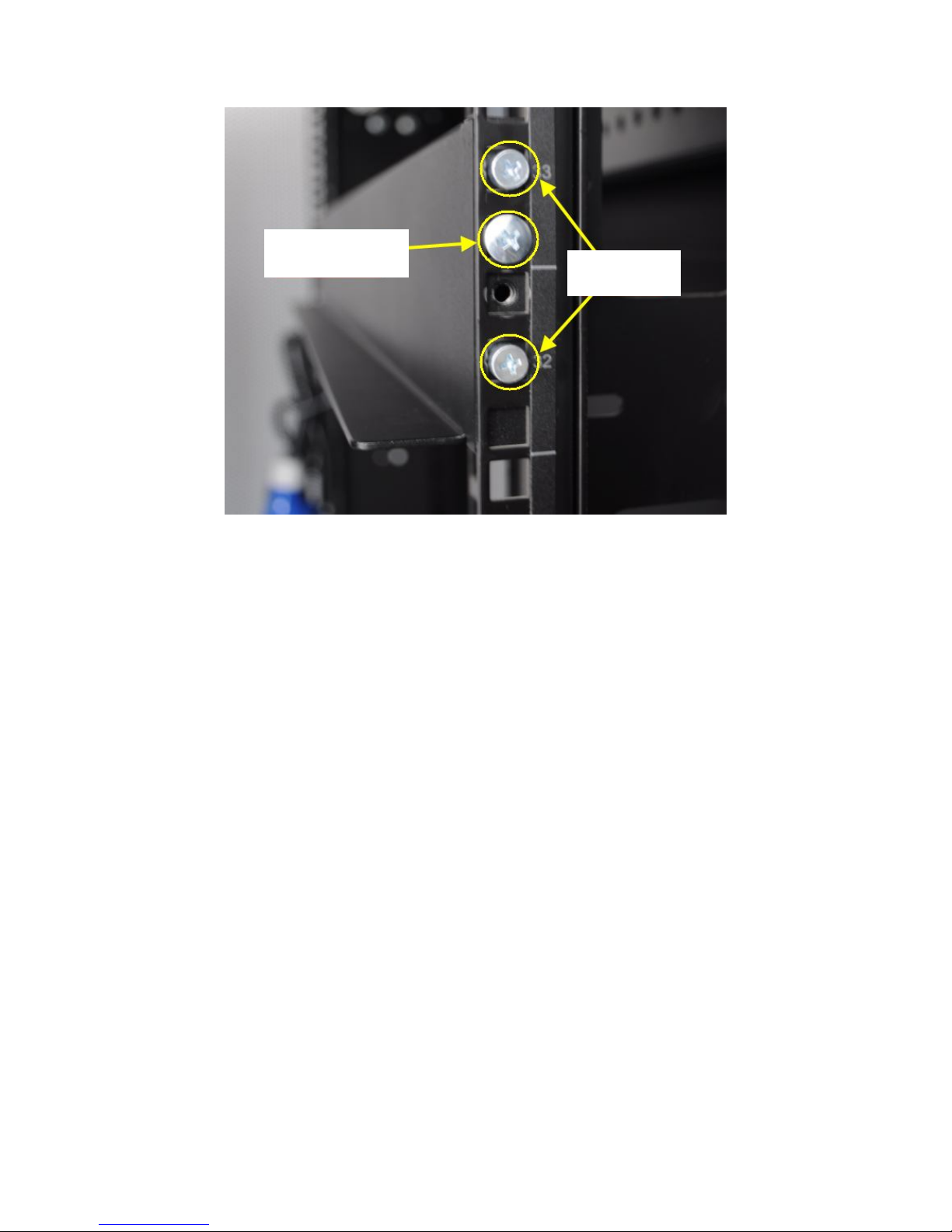
Figure 4-3
7. Fasten four fixing screws between front and rear rails.
8. Install guide rail on the other side of the cabinet, according to the above steps, be
noted that guide rails on both sides shall be leveled, that is on the same height.
4.4 Install the equipment into cabinet
Note:
For storage equipment is heavy, in order to guarantee safety, when installing storage
equipment into the cabinet, at least 4 persons are needed to move the storage system.
1. Lift the storage equipment, make it close to guide rail, and align lower angles on both
sides in front of the storage system, with angles of L-shaped rails on left and right sides.
2. To keep the storage system leveled, place the front of storage system on L-shaped guide
rail (now persons in the front shall support it to guarantee safety), push it into the
cabinet steadily, after entering about 1/3, the number of persons could be reduced to two,
finally, push the equipment into the cabinet completely, as shown in Figure 4-4.
Round head screw
Fixing column
 Loading...