


USER MANUAL – EN
IN 16187 Elliptical Trainer inSPORTline Avalor ET

2
CONTENTS
SAFETY INSTRUCTIONS ....................................................................................................................... 3
EXPLODED DRAWINGS ........................................................................................................................ 4
PARTS LIST ............................................................................................................................................ 6
PRODUCT DESCRIPTION ..................................................................................................................... 9
TECHNICAL SPECIFICATION ................................................................................................................ 9
HARDWARE LIST ................................................................................................................................. 10
ASSEMBLY INSTRUCTIONS ............................................................................................................... 12
EXERCISING INSTRUCTIONS ............................................................................................................ 15
CONSOLE OPERATION INSTRUCTION ............................................................................................. 16
LCD DISPLAY SCREEN .................................................................................................................... 16
FUNCTION DESCRIPTION ............................................................................................................... 16
MAIN FUNCTION DESCRIPTION ..................................................................................................... 17
OPERATION DESCRIPTION ................................................................................................................ 21
TERMS AND CONDITIONS OF WARRANTY, WARRANTY CLAIMS ................................................. 31

3
SAFETY INSTRUCTIONS
• Read this manual carefully before first using and keep it for future reference.
• Assemble, use and maintain it only according to this manual and for intended purpose.
• Never do any improper modification to avoid an injury.
• Keep children and pets away from this device. Never let them unattended near it.
• Regularly check all bolts and nuts. They must fit well. Regularly check it for wearing or
damage. Never use damaged or won product.
• Put it only on a flat, clean and solid surface and keep a clearance of at least 0.6 m for higher
safety. To protect floor, use a mat.
• Use it only indoors and protect it from water, humidity and dust. Assure proper ventilation.
Never use it in an airless place.
• Don’t put any sharp object on or around this device.
• Wear appropriate sports clothes and shoes. Avoid too loose clothes.
• Keep your hands away from moving parts to avoid crushing. No adjustable part should
protrude and obstruct user movements.
• Only one person can use it at time.
• Control your workout and exercise reasonably. If you feel faintly, stop using immediately.
Before starting some workout program, ask your physician for advice. It is especially required,
if you are older than 35 years, pregnant or if you suffer from some problems.
• Don’t use it, if you are pregnant or if you have some health problems such as: leg pain, waist
pain, neck pain, hand pain, arthritis, anamorphic, rheumatic, gout, osteoporosis, heart
disease, blood abnormality, hypertension, respiratory problems, oncology problems,
thrombus, diabetes, skin irritation, trauma, hyperpyrexia, bone pain, catamenia, dizziness
etc.).
• Flywheel: Inside magnet, two-way, ø450, 8 kg
• Weight limit: 150 kg
• Category: SC (according to EN957 norm) suitable for semi-commercial, hotel and club using.
• WARNING! The heart rate frequency monitoring may not be completely accurate.
Overexertion during training can lead to a serious injury or even death. If you start to feel faint,
stop the exercise immediately.
4
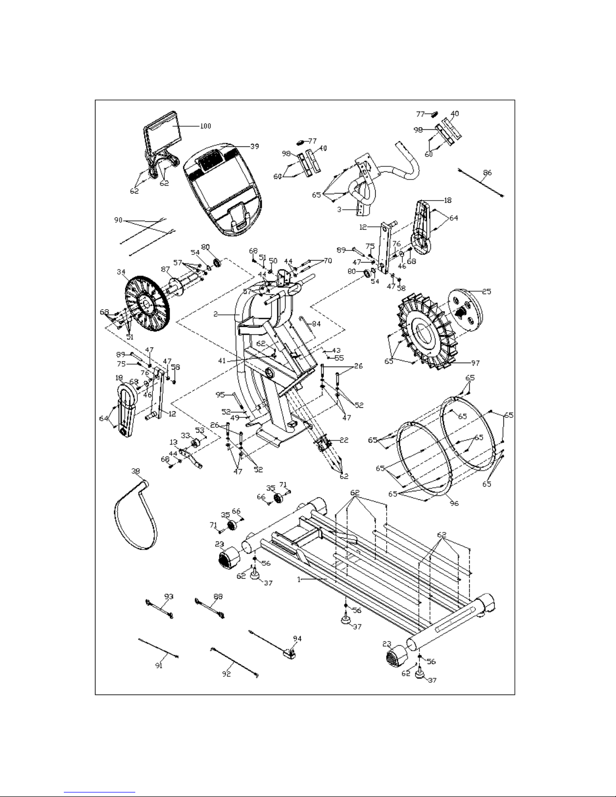
EXPLODED DRAWINGS

5

6
PARTS LIST
No.
Description
Specification
Qty. 1 Basic frame
1
2
Main frame
1 3 Console fix frame
1 4 Upper swing arm-left
1 5 Upper swing arm-right
1 6 Bottom swing arm-left
1 7 Bottom swing arm-right
1
8
Pedal group-left
1
9
Pedal group-right
1
10
Pedal connection leg-left
1
11
Pedal connection leg-right
1
12
Crank
2
13
Tension wheel fixer
1
14
Out cover-left
1
15
Out cover-right
1
16
Top cover-left
1
17
Top cover-right
1
18
Crank cover
2
19
Handlebar cover 1
2
20
Handlebar cover 2
2
21
Air outlet cover
1
22
Magnet control motor
1
23
Tube cover
4
24
Out cover decoration strip
2
25
Inside magnet flywheel
1
26
Allen cylinder head half-thread bolt
M10x70x20
4
27
Bottom wing arm cover-left
2
28
Bottom wing arm cover-right
2
29
Wheel cover
2
30
Crank axle screw cover
1
31
Pedal-left
1
32
Pedal-right
1
33
Tensioning wheel
1
34
Belt pulley
1
35
Wheel
2

7
36
Pulley
4
37
Feet pad
5
38
Motor belt
1
39
Console group
1
40
Hand pulse top cover
2
41
Magnet sensor fixer
1
42
Sliding rail aluminium sheet
670x29.5x11.2
4
43
Flat washer
Ø6xØ20xt2.0
1
44
Flat washer
Ø8.5xØ20xt1.5
11
45
Flat washer
Ø8.2xØ25xt2.0
4
46
Flat washer
Ø32xØ8.5xt2.0
2
47
Flat washer
Ø10xØ22xt2.0
8
48
Flat washer
Ø12.5xØ22xt2.0
4
49
Curved washer
Ø10.5xR100xt2.0
2
50
Curved washer
Ø8.5xR25xt2.0
7
51
Spring washer
Ø8
11
52
Spring washer
Ø10
6
53
Spring washer
Ø10
1
54
Spring washer
Ø25
2
55
Allen nut
M6
1
56
Allen nut
M10
5
57
Hex self-locking nut
M8
16
58
Hex self-locking nut
M10
2
59
Hex self-locking nut
M12
2
60
Philips CKS self-tapping screw
ST3x30
4
61
Philips CKS self-tapping screw
ST4x10
10
62
Philips CKS self-tapping screw
ST4x16
43
63
Philips CKS self-tapping screw
ST4x20
4
64
Philips CKS full thread bolt
M5x10
4
65
Philips CKS full thread bolt
M5x15
33
66
Allen pan-head full thread bolt
M6x12
4
67
Allen pan-head full thread bolt
M6x50x20
6
68
Allen pan-head full thread bolt
M8x20
12
69
Allen pan-head full thread bolt
M8x40x20
6
70
Allen pan-head full thread bolt
M8x60x20
4
71
Allen CKS hollow bolt
Ø8x33xM6x15
2
72
Allen CKS hollow screw
Ø9.4x23.5-M6/M6x12
2
73
Allen cylinder head full thread bolt
M8x15
4

8
74
Allen cylinder head full thread bolt
M12x105x15
2
75
Allen full thread bolt
M6x20
1
76
Flat key
8x10x18
1
77
Tube cap
BLF82/ø39xø30x27.5
1
78
Deep groove ball bearing
6201-ZZ
2
79
Deep groove ball bearing
6004-ZZ
2
80
Deep groove ball bearing
6005-ZZ
81
Bushing
E12/ø16xø12x6.3
82
Tube cap
Ø32x11.5
83
Foam
Ø30xt.3.0x350
84
Hook
103x Ø26xM6x50
85
Roll wheel position stopper
Ø17x Ø8.5x47
86
Brake line
L-450xØ5xØ1.2xM5
87
Crank axle group
Ø25x220
88
Communication line
L1300 mm
89
Allen half-thread bolt
M10x72x20
90
Hand pulse communication line
L650 mm
2
91
Magnet sensor
2P female connector/L300 mm
1
92
MP3 communication line
L400 mm
1
93
Power communication line
L400 mm
1
94
Power adapter
Two round plugs/240V
1
95
Allen cylinder head half-thread bolt
M10x90x20
2
96
Flywheel weight stack
6
97
Wind wheel group
Ø450x62
1
98
Hand pulse bottom cover
2
99
Pedal tape
2
100
I-pad holder
1
101
Air outlet bottom cover
1
102
Hinge
4
103
Sliding wheel hinge
1
104
Hinge fix plate
1
9
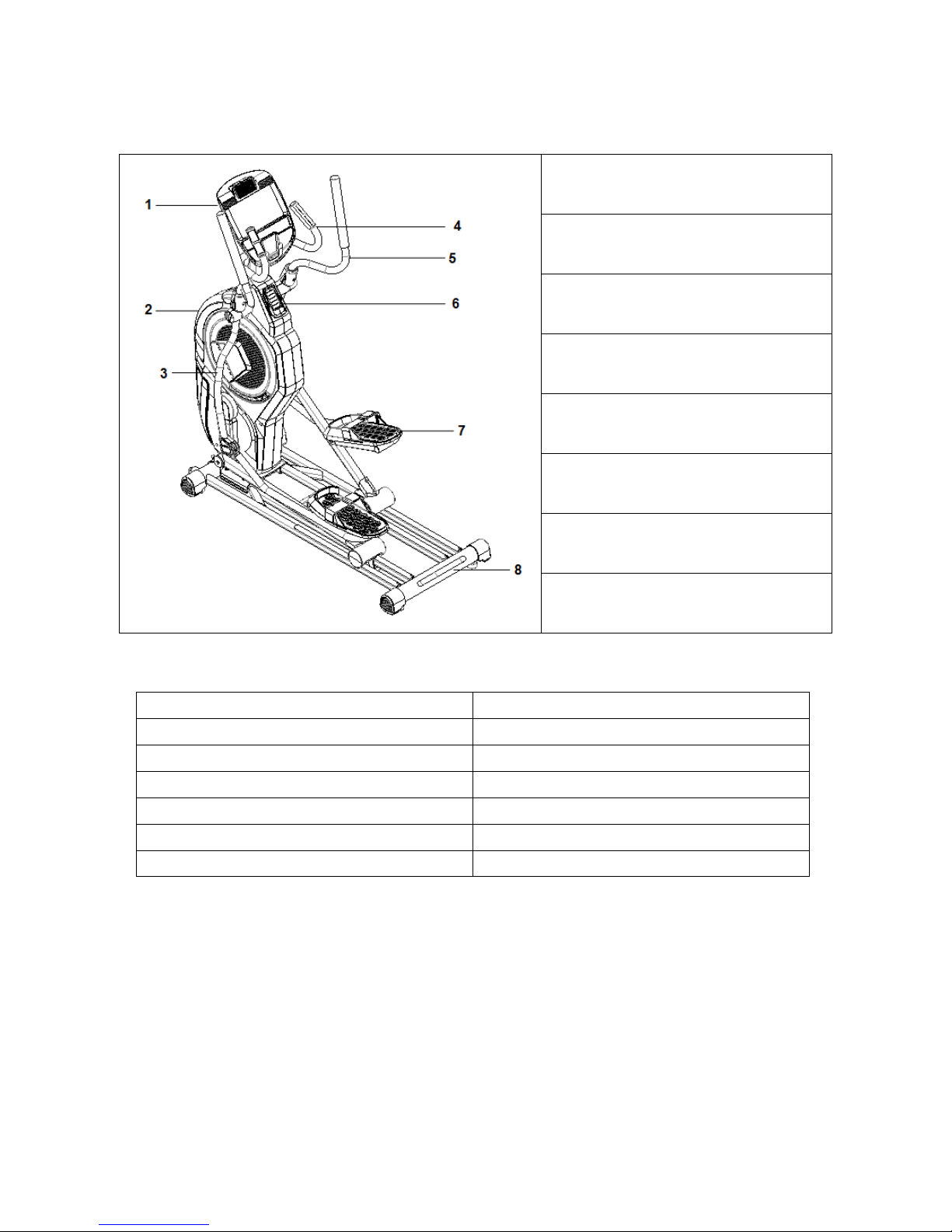
PRODUCT DESCRIPTION
1) Console
2) Main frame
3) Arm
4) Handlebar
5) Arm top
6) Air outlet
7) Pedal
8) Basic frame
TECHNICAL SPECIFICATION
Model No.
E15
Dimensions (unfolded)
1600x650x1770 mm
Max. user weight
150 kg
Speed ratio
8.8
Flywheel
Inside magnet, two-way, ø450, 8 kg
Resistance level
1-24
Stride length
520x240
NOTE: The producer reserves the right to amend this product without prior notice.

10
HARDWARE LIST
No.
Description
Specification
Qty.
26
Allen cylinder head half-thread bolt
M10x70x20
4
44
Flat washer
Ø8.5xØ20xt1.5
4
45
Flat washer
Ø8.2xØ25xt2.0
4
47
Flat washer
Ø10xØ22xt2.0
4
49
Curved washer
Ø10.5xR100xt2.0
2
50
Curved washer
Ø8.5xR25xt2.0
7
51
Spring washer
Ø8
3
52
Spring washer
Ø10
6
57
Hex self-locking nut
M8
10
62
Philips CKS self-tapping screw
ST4x16
10
65
Philips CKS full thread bolt
M5x15
12
66
Allen pan-head full thread bolt
M6x12
2

11
67
Allen pan-head full thread bolt
M6x50x20
6
68
Allen pan-head full thread bolt
M8x20
5
69
Allen pan-head full thread bolt
M8x40x20
6
70
Allen pan-head full thread bolt
M8x60x20
4
72
Allen CKS hollow screw
Ø9.4x23.5-M6/M6x12
2
95
Allen cylinder head half-thread bolt
M10x90x20
2
TOOLS:
L Wrench
5x80x80S
1
L Wrench
5x35x85S
1
L Wrench
6x40x120
1
L Wrench
8x45x145
1
Philips wrench
14x17x75
1
Open end wrench
15&17
1
12
ASSEMBLY INSTRUCTIONS
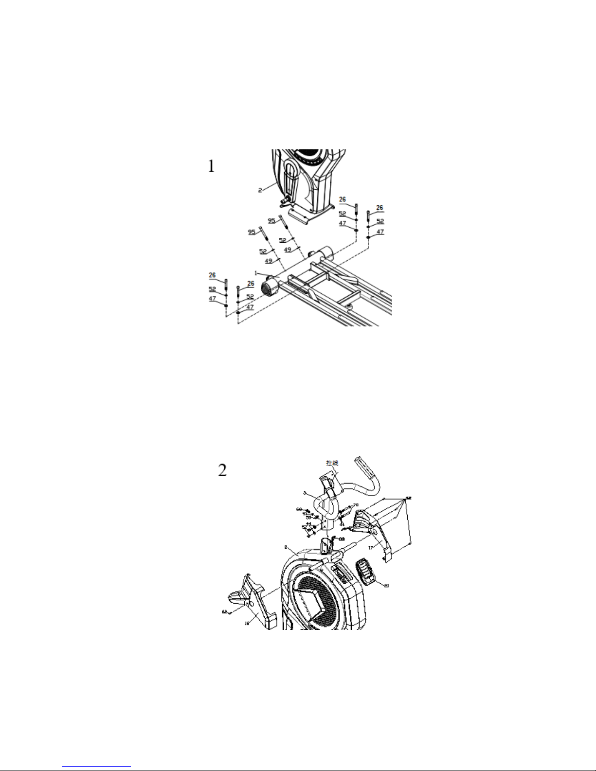
STEP 1
• Place the main frame (2) on the basic frame (1), secure with two Allen cylinder head halfthread screws (95), two spring washers (52), two curved washers (49), four Allen cylinder
head half-thread screws (26), four spring washers (52) and four flat washers (47).
STEP 2
• Pull out the communication line (88) from hole of the console fix group (3).
• Assemble the console fix group (3) on the main frame (2). Secure with one curved washer
(50), one spring washer (51), one Allen pan head full-thread bolt (68), four flat washers (44),
two hex self-locking nuts (57), two Allen pan head half-thread bolts (70).
• Attach the left top cover (16), right top cover (17) and the air outlet cover (21). Secure with six
Phillips CKS self-tapping screws (62).
• WARNING! After the communication line is connected, insert all lines into the upright post to
avoid line clamping. First put all bolts and washers onto the frame holes and secure them.

13
STEP 3
• Assemble the bottom swing arm (6) to the main body and secure with one Allen pan head fullthread bolt (68), one spring washer (51), one flat washer (45).
• Assemble the top swing arm (4) onto the bottom swing arm (6) and secure with three Allen
pan head full-thread bolts (69), three curved washers (50) and three hex self-locking nuts (57).
• Secure the handlebar cover (19) and the handlebar cover (20) at the top of the bottom wing
arm connection using four Phillips CKS full-thread bolts (65).
• Assemble the right side following the same steps above.
STEP 4
• Secure the left pedal (31) using one Allen pan head full thread bolt (66) and three Allen pan
head full-thread bolts (67) on the left pedal connection leg (10).
• Assemble the right side following the same steps.
STEP 5
• Assemble the left pedal group (8) on the railway and secure with one flat washer (45), one
crank axle screw cover (30) and one Allen pan head full-thread bolt (68).
• Connect left pedal connection leg (10) with bottom wing arm (6) and secure with one Allen
CKS hollow screw (72).
• Attach the left bottom swing arm cover (27) and the right bottom swing arm cover (28) on the
left swing arm (6). Secure with two Philips CKS self-tapping screws.
• Assemble the right side following the same steps.

14
STEP 6
• Assemble one roll wheel position stopper on the left pedal connection leg (10) and secure with
one Allen pan head full-thread bolt (70) and one hex self-locking nut (57).
• Assemble the right side following steps above.
STEP 7
• Connect the communication line (88), the hand pulse communication line (90) with the console
communication line together.
• Insert the communication line into the hole on the console fix frame and secure with four
Philips CKS full-thread bolts (65).

15
STEP 8
• Place the I-pad holder (100) onto the console assembly (39) and secure with four Philips CKS
self-tapping screws (62).
• WARNING! This step is needed if you want to buy an I-pad. Otherwise you can leave this step
out.
EXERCISING INSTRUCTIONS
A successful workout begins with warm-up exercises and ends with cool-down (relaxing) exercises.
The warm-up exercises should make your body ready for the main workout. The cool-down phase
should protect your muscles from injuries and cramps. Do warm-up and cool-down exercises as
shown in the chart below.
Touching your toes
Slowly bend your back from hips. Keep your back and arms relaxed while
stretching downwards to your toes. Do it as far as you are able and hold the
position for 15 seconds. Bend your knees slightly.
Upper thigh
Lean against a wall with one hand. Reach down and behind you. Lift up your
right or left foot to your buttock as high as possible. Keep for 30 seconds and
repeat twice for each leg.
Hamstring stretched
Sit and outstretch your right leg. Rest the sole of your left foot against the inside
of your right tight. Stretch out your right arm along your right leg as far as you
can. Hold for 15 seconds and relax. Repeat all with your left leg and left arm.
Inside upper thigh
Sit on the floor and place your feet together. Knees are pointed outwards. Pull
your feet as close as possible to your groin. Press your knees carefully
downwards. Keep this position for 30-40 seconds if possible.
Calves and Achilles tendon
Lean against a wall with your left leg in front of the right one and your arms
forward. Stretch out your right leg and keep your left foot on the floor. Bend your
left leg and lean forwards by moving your right hip in the direction of the wall.
Hold for 30-40 seconds. Keep your leg stretched and repeat exercising with
other leg.

16
CONSOLE OPERATION INSTRUCTION
LCD DISPLAY SCREEN
FUNCTION DESCRIPTION
1. Manual: adjustable manual mode
2. Program: 12 profiles (P1~P12) for automatic load level adjusting
3. WATT: Displaying the power consumption during training.
4. HRC (heart rate): Set 55%/ 75%/ 90%. It adjusts the load level base of the heartbeat
automatically.
5. User program: self-selected load level for exercising.
6. Recovery: recovery heart rate test.
7. Body fat: testing the body fat of the user.
8. User data: set user information. Possible to choose the UX (X=1~4)
9. Music speaker
10. USB charging function

17
MAIN FUNCTION DESCRIPTION
FUNCTION
DISPLAY
RANGE
SETTING
RANGE
MEMORIZE
RETURN TO
ZERO STATE
DESCRIPTION
TIME
0:00~99:59
min.
0~99
circulation
(+/- 1 min.)
yes
yes
• Counting up without
preset target. The
time will count up from
0:00.
• Count down – with
preset target value,
the time will be
counted down from
the preset value to “0”.
Thereafter it stops.
The indicator light of
the TIME flashes and
the system alarm
gives sounds every
second. To stop it,
push any button.
SPEED
0.0~99.9 km/h
(0.0~99.9 MLH)
It cannot be
preset.
no
yes
In the START mode:
a) With sensor input,
screen displays
training speed in 3
seconds.
b) Without sensor input
for 4.6 second the
SPEED value is 0.
c) SPEED and RPM
value will display for 6
seconds by turn in the
same window.
RPM
0~999
It cannot be
preset.
no
yes
In the START mode:
a) With the sensor input
the screen displays
training RPM in 3
seconds.
b) Without sensor input
for 4.6 second the
RPM value is 0.
c) SPEED and RPM
value will display for 6
seconds by turning
into the same window.

18
DISTANCE
0.0~99.99 km
(ml)
0.0~99.90
(+/-0.1)
yes
yes
a) Count up – no preset
target. The distance
will count up from 0.0.
b) Count down – with
preset target the
distance will count
down from the preset
value to 0 and then it
stops. The indicator
light of the DISTANCE
flashes and the
system alarm 8
seconds with 4
sounds in every
second. Push any key
to stop it.
CALORIES
0~9999 cal
0~9990 cal
(+/-10)
yes
yes
a) Count up – no preset
target. The
CALORIES will count
up from 0.
b) Count down – with
preset target the
CALORIES will count
down from preset
value to 0. Then it
stops. The indicator
light of calories
flashes and system
alarm 8 seconds with
4 sounds in every
second. Push any key
to stop the alarm.
PULSE
P-30~230 BPM
0-30~230
(+/-1) BPM
circulation
yes
yes
a) With pulse input the
screen display the
initial value in 7.5
seconds.
b) Without any pulse
input in 6 seconds, the
PULSE value is 0.
c) If pulse exceeds the
preset target, the
console will remind wit
sound Bi-Bi.
WATT
0~999
It cannot be
preset.
yes
yes
a) With sensor input the
screen displays WATT
value in 3 seconds.
b) Without any sensor
input for 4.6 seconds
the WATT value is 0.
AGE
1~99
1~99
yes
yes
The indicator light flashes
while waits for preset. The
screen display default
value is 25.

19
RECOVERY
F1~F6
It cannot be
preset.
no
no
To display the PULSE
input value.
MANUAL
1~24 levels
yes
yes
a) Press key to
preset the level.
b) CPU adjust the
resistance base on
LEVEL preset value.
PROGRAM
(P1~P12)
(P1~P12)
yes
yes
a) Pres key to
preset PROGRAM.
When you select the
indicator light flashes.
Press MODE to
confirm your selection.
b) CPU adjusts the
resistance base on
LEVEL preset value.
USER
16X*8Y
yes
yes
a) When you select the
indicator light flashes.
Push MODE to
confirm the selection.
b) USER can preset one
PROGRAM.
H.R.C.
55%, 75%,
90%, TAG
yes
yes
a) When you select, the
indicator light flashes.
Press MODE to
confirm your selection.
b) Before preset it, you
should set in your
AGE first.
WATT
CONSTANT
(10~350, +/-
5) circulation
yes
yes
a) When you select, the
indicator light flashes.
Push MODE to
confirm your selection.
b) The default value is
120. After the preset is
finished, push the
START to conduct this
WATT CONSTANT
function.
WHEEL
It cannot be
preset.
yes
yes
Select by OPTION.
LEVEL
Display 1~24
1~24
no
no
Screen displays LEVEL
value when you select
and adjust this function.
SEX
Male or female
Male or
female
yes
no
Select male or female.

20
HEIGHT
100~200 cm
100~200 (+/1 cm), 40~80
(+/-1) inch
yes
yes
a) Set the height of the
user as the calculation
parameter of the
exercise. The preset
value is 160 cm (60
inch).
b) When you select the
indicator light of the
WT flashes.
WEIGHT
20~150 kg
20-150 kg
(+/-1 kg),
40~350 lb
(+/-1)
yes
yes
a) Set the weight of the
user as the calculation
parameter of exercise
preset value is 50 kg
(100 lb).
b) When you select the
indicator light of WT
flash.
BODY FAT
5.0%~50%
It cannot be
preset
no
no
LED display.
BMI
0~50
It cannot be
preset.
yes
no
LED display.

21
OPERATION DESCRIPTION
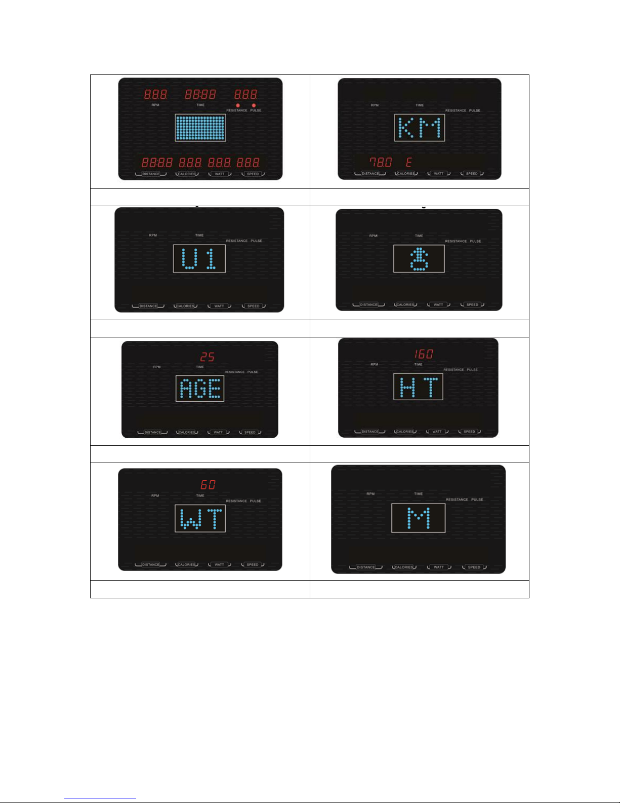
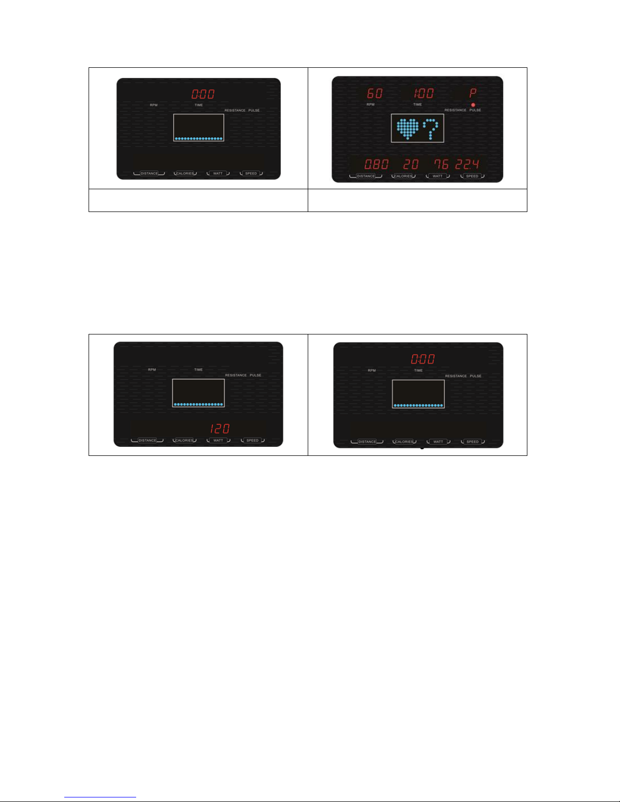
POWER ON
1. When plug in adapter (or when step RPM>15, self-power generation), buzzer sounds for 1
second and LED will full display for 2 seconds (Pic. 1). Then it displays KM or ML in center of
screen.
2. Enter USER setting mode (with FAT function), input user information U1~U4. Select one user
drawing (Pic. 3). Push MODE key to select SEX (Pic. 4), AGE (Pic. 5), HEIGHT (Pic. 6),
WEIGHT (Pic. 7). When you select, the window shows the default value or previous record.
Press UP/DOWN key to adjust the value. Then go to main function window (Pic. 8). MANUAL
PROGRAM, USER PROGRAM, HRC, WATT FUNCTION. Finish all settings and press
START/STOP to exercise.
SLEEP: If SM and SE is without any RPM information input within 4 minutes, the console will enter
the sleep mode. The console will wake up if any RPM information input.
SR system without any RPM information input 90 seconds, the console will be in the sleep mode.
The console will wake up when the sensor input > 15 RPM.
22
Pic. 1
Pic. 2
Pic. 3
Pic. 4
Pic. 5
Pic. 6
Pic. 7
Pic. 8
Function circulation: MANUAL – PROGRAM – USER – WATT

23
Pic. 9
Pic. 10
Pic. 11
Pic. 12
Pic. 13
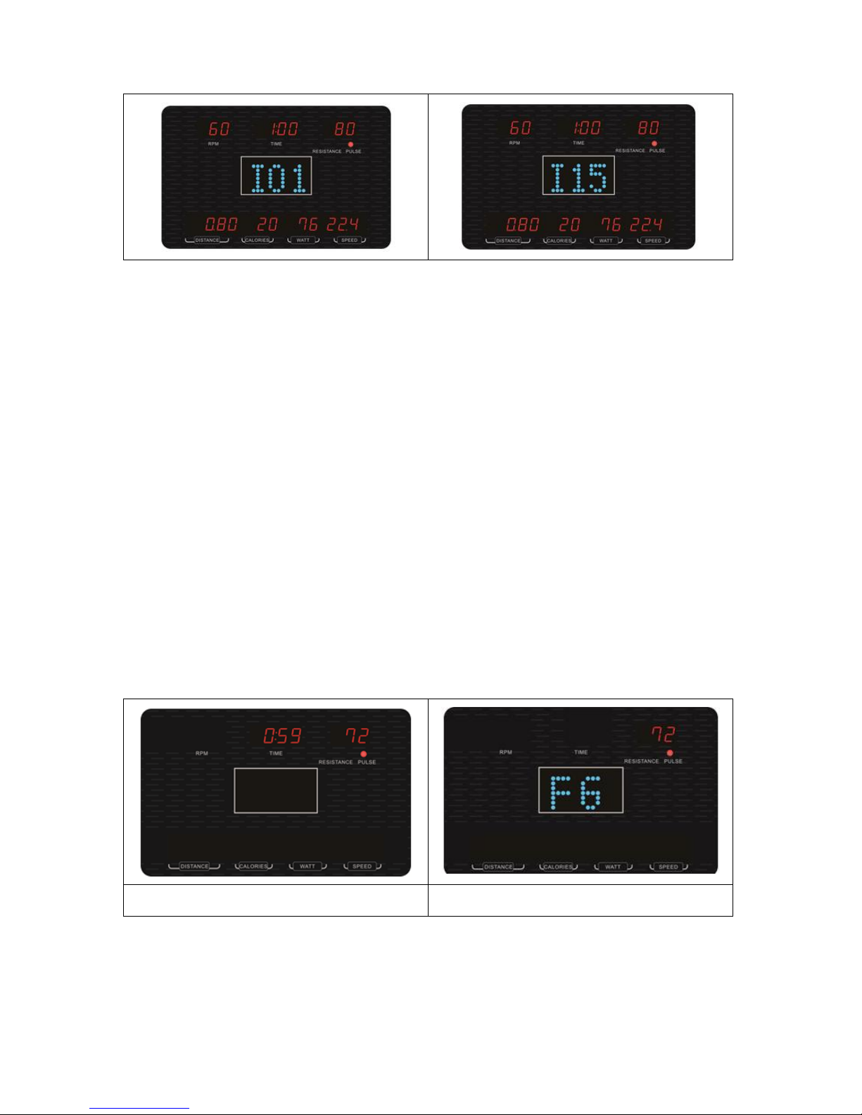
MANUAL MODE (PRESS START/STOP KEY)
A. Select MANUAL mode to adjust the setting value. Use MODE key to select. Press UP/DOWN
to select the value. TIME (Pic. 14), DISTANCE (Pic. 15), CALORIES (Pic. 16), PULSE (Pic.
17).
B. Push START/STOP key to start exercising. Press UP or DOWN key to adjust the resistance
during exercising. Re-press START/STOP key and the console will pause. Press RESET to
enter main function selection window.

24
Pic. 14
Pic. 15
Pic. 16
Pic. 17
PROGRAM MODE
A. Select PROGRAM mode, push UP/DOWN to select P1~P2 (Pic. 18 – 29).
B. Enter time window, push UP/DOWN key to adjust it (Pic. 30).
C. Press START/STOP key to start exercising. Press UP or DOWN key to adjust resistance
during exercising.
D. Repress START/STOP key and console will pause. Press RESET to enter main function
selection window.
Pic. 18
Pic. 19

25
Pic. 20
Pic. 21
Pic. 22
Pic. 23
Pic. 24
Pic. 25
Pic. 26
Pic. 27

26
Pic. 28
Pic. 29
Pic. 30
Pic. 31
Pic. 32
Pic. 33
USER MODE
A. Select USER mode. Push UP/DOWN key to set the USER PROGRAM (Pic. 34). Push MODE
key 2 seconds to skip this setting (keep previous record or keep as LOAD 1 if no setting
before).
B. Enter the time window. Press UP/DOWN key to adjust it (Pic. 35).
C. Press START/STOP key to start exercising. Press UP or DOWN key to adjust resistance
during exercising.
D. Repress START/STOP key and the console will pause. Press RESET to enter the main menu
function selecting window.

27
Pic. 34
Pic. 35
HRC MODE
A. Enter HRC mode and press UP/DOWN key to select 55% (107), 75% (146), 90% (175) TAG
(100) (Pic. 36-39).
B. Enter the time window and press UP/DOWN key to adjust it (Pic. 40).
C. Press START/STOP key to start exercise. Press UP or DOWN key to adjust resistance during
exercise.
D. Repress START/STOP key and the console will pause. Press RESET to enter the main
function selection window.
E. The window will show if there is no heartbeat input (Pic. 41).
Pic. 36
Pic. 37
Pic. 38
Pic. 39
28
Pic. 40
Pic. 41
WATT MODE
A. Enter the WATT mode. Press UP/DOWN key to adjust the value. Default value is 120 W (as
shown below).
B. Enter the TIME window, press UP/DOWN key to adjust it (as shown below).
C. Press START/STOP key to start exercising. Base on the value of WATT to adjust resistance
automatically.
D. Repress START/STOP key and the console will pause. Press RESET to enter main function
selection window.
KEY OPERATION:
• Console with key alarm function (valid KEY: 1 short sound, invalid KEY: 2 short sound, count
down to zero: 4 short sounds in every second. HRC and WATT CONTROL stop forcedly. 6
short sounds continuously. PULSE over setting value: 2 short sounds in every second. WATT
OVER SPEC: 3 short sounds in every second.
UP/DOWN KEY
1. Press up this button to add or to reduce value 1. Long press to add or to reduce the value
continuously.
2. Select user U1~U4 (age, sex, weight, height)
3. Select MANUAL, PROGRAM, USER, HRC, WATT function.
29
MODE KEY
1. Select function (TIME, DIST, CAL, PULSE) etc.
2. After selecting or putting a preset value, press this key to go to the next step.
RESET KEY
1. RESET: Press RESET key when the system is under the STOP state. Enter the main function
window to select (WATT, HRC, USER, PROGRAM, MANUAL function) and clear previous
record of TIME, DISTANCE, CALORIES, PULSE, WATT).
2. TOTAL RESET: Press RESET key 2 seconds to enter to just power on state, that is TOTAL
RESET. System gives 1-second sound alarm and enters setting mode 2 seconds later. The
system is stand by LEVEL 1, waiting for the preset.
START/STOP KEY
Press this key to start exercise, press it one more time to stop the console.
RECOVERY
1. If there is no PULSE input, this key is invalid.
2. In the START or STOP state it displays the PULSE value. Press the RECOVERY KEY to:
a) Conduct RECOVERY function, display only TIME and PULSE window. Voltage value of
LEVEL will be reduced to LEVEL 1 immediately.
b) The TIME window displays 0:60 (Pic 43). Start counting down. If there is no pulse input
during the time count-down, the window displays F1~F6, when the TIME counts down to
0. Press the RECOVERY key to resume display.
3. Press this key during time count-down and resume normal display.
Pic. 43
Pic. 44
BODY FAT
1. Under the STOP state, after finishing user information, this function is ready.
2. Press this key to test the body fat ratio. Put your hands onto handlebar and the test result will
be displayed on the window (Pic. 45 – 47). If the window displays E-1 (Pic. 48), it means you

30
don’t hold the handlebars closely. If the window displays E-4 (Pic. 49), the body fat ratio is
over the setting range (5~50%).
3. After testing, the FAT% and the BMI will be displayed in the window (Pic. 50, 51, 52).
4. Press the BODY FAT key one more time during testing to cancel this function.
Pic. 45
Pic. 46
Pic. 47
Pic. 48
Pic. 49
Pic. 50
Pic. 51
Pic. 52

31
TERMS AND CONDITIONS OF WARRANTY, WARRANTY CLAIMS
General Conditions of Warranty and Definition of Terms
All Warranty Conditions stated hereunder determine Warranty Coverage and Warranty Claim
Procedure. Conditions of Warranty and Warranty Claims are governed by Act No. 40/1964 Coll. Civil
Code, Act No. 513/1991 Coll., Commercial Code, and Act No. 634/1992 Coll., Consumer Protection
Act, as amended, also in cases that are not specified by these Warranty rules.
The seller is SEVEN SPORT s.r.o. with its registered office in Borivojova Street 35/878, Prague
13000, Company Registration Number: 26847264, registered in the Trade Register at Regional Court
in Prague, Section C, Insert No. 116888.
According to valid legal regulations it depends whether the Buyer is the End Customer or not.
“The Buyer who is the End Customer” or simply the “End Customer” is the legal entity that does not
conclude and execute the Contract in order to run or promote his own trade or business activities.
“The Buyer who is not the End Customer” is a Businessman that buys Goods or uses services for the
purpose of using the Goods or services for his own business activities. The Buyer conforms to the
General Purchase Agreement and business conditions to the extent specified in the Commercial
Code.
These Conditions of Warranty and Warranty Claims are an integral part of every Purchase Agreement
made between the Seller and the Buyer. All Warranty Conditions are valid and binding, unless
otherwise specified in the Purchase Agreement, in the Amendment to this Contract or in another
written agreement.
Warranty Conditions
Warranty Period
The Seller provides the Buyer a 24 months Warranty for Goods Quality, unless otherwise specified in
the Certificate of Warranty, Invoice, Bill of Delivery or other documents related to the Goods. The legal
warranty period provided to the Consumer is not affected.
By the Warranty for Goods Quality, the Seller guarantees that the delivered Goods shall be, for a
certain period of time, suitable for regular or contracted use, and that the Goods shall maintain its
regular or contracted features.
The Warranty does not cover defects resulting from (if applicable):
• User’s fault, i.e. product damage caused by unqualified repair work, improper assembly,
insufficient insertion of seat post into frame, insufficient tightening of pedals and cranks
• Improper maintenance
• Mechanical damages
• Regular use (e.g. wearing out of rubber and plastic parts, moving mechanisms, joints etc.)
• Unavoidable event, natural disaster
• Adjustments made by unqualified person
• Improper maintenance, improper placement, damages caused by low or high temperature,
water, inappropriate pressure, shocks, intentional changes in design or construction etc.
Warranty Claim Procedure
The Buyer is obliged to check the Goods delivered by the Seller immediately after taking the
responsibility for the Goods and its damages, i.e. immediately after its delivery. The Buyer must check
the Goods so that he discovers all the defects that can be discovered by such check.
When making a Warranty Claim the Buyer is obliged, on request of the Seller, to prove the purchase
and validity of the claim by the Invoice or Bill of Delivery that includes the product’s serial number, or
eventually by the documents without the serial number. If the Buyer does not prove the validity of the
Warranty Claim by these documents, the Seller has the right to reject the Warranty Claim.

32
If the Buyer gives notice of a defect that is not covered by the Warranty (e.g. in the case that the
Warranty Conditions were not fulfilled or in the case of reporting the defect by mistake etc.), the Seller
is eligible to require a compensation for all the costs arising from the repair. The cost shall be
calculated according to the valid price list of services and transport costs.
If the Seller finds out (by testing) that the product is not damaged, the Warranty Claim is not accepted.
The Seller reserves the right to claim a compensation for costs arising from the false Warranty Claim.
In case the Buyer makes a claim about the Goods that is legally covered by the Warranty provided by
the Seller, the Seller shall fix the reported defects by means of repair or by the exchange of the
damaged part or product for a new one. Based on the agreement of the Buyer, the Seller has the right
to exchange the defected Goods for a fully compatible Goods of the same or better technical
characteristics. The Seller is entitled to choose the form of the Warranty Claim Procedures described
in this paragraph.
The Seller shall settle the Warranty Claim within 30 days after the delivery of the defective Goods,
unless a longer period has been agreed upon. The day when the repaired or exchanged Goods is
handed over to the Buyer is considered to be the day of the Warranty Claim settlement. When the
Seller is not able to settle the Warranty Claim within the agreed period due to the specific nature of the
Goods defect, he and the Buyer shall make an agreement about an alternative solution. In case such
agreement is not made, the Seller is obliged to provide the Buyer with a financial compensation in the
form of a refund.
SEVEN SPORT s.r.o.
Registered Office: Borivojova 35/878, 130 00 Praha 3, Czech Republic
Headquarters: Delnicka 957, 749 01 Vitkov, Czech Republic
Warranty & Service Centre: Cermenska 486, 749 01 Vitkov, Czech Republic
CRN: 26847264
VAT ID: CZ26847264
Phone: +420 556 300 970
E-mail: eshop@insportline.cz
reklamace@insportline.cz
servis@insportline.cz
Web: www.insportline.cz
SK
INSPORTLINE s.r.o.
Headquarters, Warranty & Service centre: Elektricna 6471, 911 01 Trencin, Slovakia
CRN: 36311723
VAT ID: SK2020177082
Phone: +421(0)326 526 701
E-mail: objednavky@insportline.sk
reklamacie@insportline.sk
servis@insportline.sk
Web: www.insportline.sk
Date of Sale: Stamp and Signature of Seller:
 Loading...