

Page 1
OP ER ATI ON M AN UA L
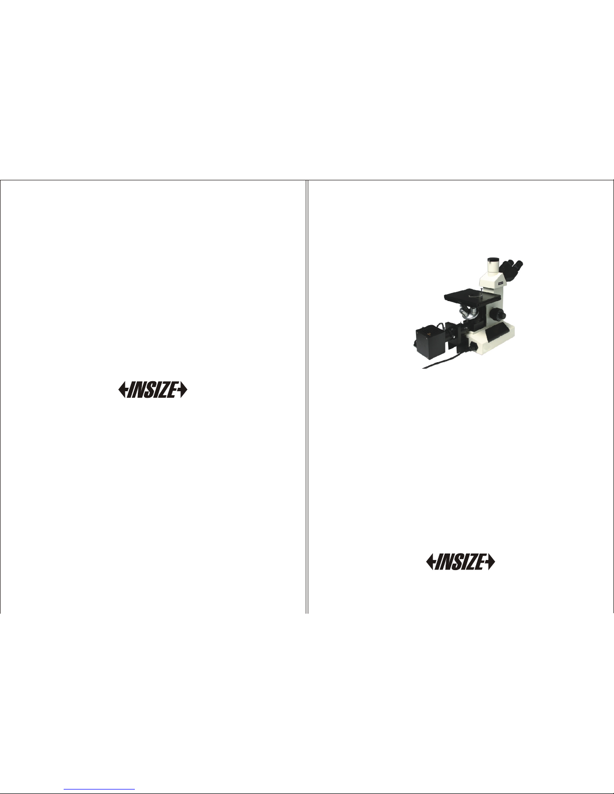
ISM-M1000
Metallurgi cal Mic rosco pe
www.insize.com
Page 2
Congratulations and Thank You for your purchase of
The Microscope
Gettin g Sta rted 3
Compon ent s 4
Technica l Spe cifi cat ions 5
Setup In str ucti ons 5
Basic Op era tion 6
Changi ng th e Lamp 10
Changi ng th e Fuse 11
Preven tat ive Ma int enance 12
PLEASE DISCONNECT PLUG FROM MAINS SOCKET BEFORE REMOVING
THE BOTTOM PLATE, OPENING THE LAMP REPLACEMENT DOOR, OR
REMOVING THE LAMP HOUSE
THE POWER CORD PROVIDED WITH THE EQUIPMENT HAS A GROUNDED
PLUG. ALWAYS USE TH E POWER CORD WITH A PROPERLY GROUNDED
WALL OUTLET.
DO NOT EXP OSE THE INS TRUMEN T TO HIGH TEMPERATURE S OR
HUMIDITY. AVOID USI NG THE INST RUMENT IN E XTREME LY DUST Y
LOCATIONS.
OPERATING TE MPERATURE 5°C TO 35°C
OPERATING HUMIDITY: 20% TO 80% @ 25°C
WARNING
WARNING
1 2
Conte nts
This precis ion instru ment has been designed to re quire a minimum of
opti cal and mechanical main tenance. Its ex cellent design assures yea rs
of high quality, reliabl e service. We recommend you read this entire
manu al carefully before beginning to us e the inst rument .
CAUTION: NEVER IMMERSE THE INS TRUMENT IN WATER OR SOLVENT
CAUTION: DO NOT PUT ANY FOREIGN OBJECTS IN THE FRAME OR INTO
ANY MOV ING MECHANICAL PARTS
Page 3
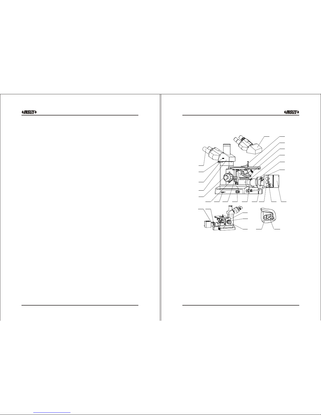
12
7
8
9 10
13
14
15
16
17
18
19
20
21
1
2
3
4
6
5
11
28
27
26
24
25
22
23
Figure 1
This guide is written on the assumption that it will be used by advanced
stud ents and exp erienc ed micros copists. It covers th e essenti al
adjustments and controls of microscopes. No attempt has been made to
include fundamentals of mi croscopy. Read th is guid e prior to unpacking
the microsco pe. This guide is designe d to illustrate a sequen tial method
for assembly and operati on. We recommend the instruct ions be fol lowed
in a sequen tial process . After assembling the instru ment, re-read the
guide and become familiar with all adjustments and functions befo re
using your new microscop e.
Compo nents
3 4
Getting Started
1.Eyepiece 2.Switch Handspike For Observe/Photograph 3.
Thumbscrew 4.Trinocul ar 5. Up Stop 6. Table-board Longitudinal
Adjustment Knob 7. Brigh tness Contr ol K nob 8. Table-board
Transv erse Adjustment Knob 9. Power Switch 10. Field Di aphragm
Centering Screw 11. Focusing Lens Adjustment Le ver 12. Light Bulb
Vertical Adjustment knob 13. Lig ht Bulb Transverse Adj ustment knob
14. Lamp House 15. Filter Wheel 16. Aperture Diaph ragm Adjustment
Lever 17. Field Di aphragm Adjustment Le ver 18.Objectiv e 19.Stage
20.Stretchy Cli p 21.Bi nocular 22.Polarizer (Optional) 23 Lamp
House Set Screw.24. Focus Tension al Ad justment Knob 25.Coarse
Focus Control Knob 26. F ine Foc us Control Knob 27. Pow er Outl et
with Fuse Seat 28. Powe r Inle t
Page 4

Magnification
10X
20X
40X
100X(Spring,Oil)
W.D.(mm)
8.8
8.6
3.73
0.33
N.A.
0.25
0.40
0.60
1.25
Type(no cover glass)
Plan achromatic
Technical Specifications
Trinocular: Inclined 30° .
Objectives:
Nosep iece: Quad ruple nose piece ball-bearing reversed nosepiece with
positiv e clic k stops and smooth operation.
Eye piece s: 10X wide fi eld ey epiec e, foc al length 25m m, fie ldØ18 mm.
Stage: Double layer mech anical,
Size: 180mmX150mm,
Moving range: 15mmX15m m.
Filters: Ground glass, b lue filte r, green filter and yellow filter.
Illumination: 6V/20W h alogen la mp, adjustable brightness.
Power supply: 220V(50/ 60HZ) or 110V(50/60HZ).
Anti-fungus: Yes.
Setup Instructions
1. Remo ve all parts from their packing m ateri als and reta in the
packaging in the event you need to trans port the produc t.
2. Conn ect the powe r cord to a suitabl e p ower supply.
Fig ure 2
Fig ure 3
Th e p owe r s wit ch to th e
illuminator and the brightness
control is located on the ba se.
The electr ical system is fuse
protected and the fuse holder
located on the socket.
Tur n on the l igh t with th e
power s wit ch, s ee f igure 2. If
the ligh t doe s not app ear to
be ON, che ck the brightn ess
contro l t o s ee if it 's on a
suffic iently low sett ing . Th en
adjust the brig htness control
until ima ge can be obs erv ed
comfor tab ly.
Note: Us ing t he li ght at
bright est s etting r educes
life sp an o f lam p.
Fo cu si ng ad ju st ment i s
accomplished by using the
la rg e c oa rs e adj us tm en t
knobs located comfortably on
each side of the frame. Fine
adjustment is accomplished
us in g th e s ma ller k no bs
located on the same focus
shaft. This coaxial arrangement
al low s f or easy, p re ci se
adj us tm en t w it ho ut d ri ft
or discomfort.
Basic O peration
1. Illum ina tion c ont rols
1)
2)
2. Focus ing C ontr ols
1. Br ightn ess Con trol Kn ob
2. Po wer Swi tch
1. Fo cus Tensi on Adju stme nt
K n ob
2. Up S top
3. Co arse Fo cus Con trol Kn ob
4. Fi ne Focu s Contr ol Knob
1)
5 6
1
2
1 2
3
4
Page 5

Focus Control Turning either of the coarse focus control knob s
will raise or low er the stage. The smallest gr aduation on the fine
adjust knob i ndex scale is 2μm of ve rtical.
Focus Tension Adjus tment The tension of the coarse focus is
adjustable and p reset at the fact ory for ease of use. If you wish to
adjust the coarse focus tension, firs t locate the tension adjustment
ring, It is located between the frame and c oarse adjust ment knob.
Turning t he ring toward the rear of the microscope increases the
tension, and towar d the f ront of the microscope loos ens it. Tensio n
is too high if you experi ence physical discomfort.
Pre-focusing or Focus St op Control Use of this fea ture will
insure that the shorter working distance objectives don't contact
the stage or specime n when using the microscope. Its use also
simplifies focusin g. After focusing on the specimen wi th the coarse
adjustment by low magnification eyepiece, rota tion of th e lever
toward the han dler will set and upper limit on the coars e
adjustment m ovement . After changing s pecimens or objectives ,
focusing is easily accomplished by rotati ng the coarse adjustment
kno b to reach th e pr e-focused pos itio n, then mak ing fine
adjustments with the fine adju stment kno b. Focusing movement
with the fine adjustme nt isn't affected by using the pre-f ocusing
lever.
Di opte r A dj us tm en t P ro pe r
correction for individual visi on is
ac complished vi a t he di opt er
adju stment located at the le ft
eyepiece, see figure 4. Usi ng the
40X ma gnifica tion objective, b ring
An image into focu s with your righ t
eye only. Once the image is w ell
focused, o bserve with left ey e,
make fine ad justments wit h the
diopter Adju stment ring to correct
for your Vision.
Proper interpu pillary distance , Or the distance between
eyepi eces, is crucial to the c omfort of the user. Adjusting the
inter pupillary dist ance is accompli shed through a “folding” a ction of
the optica l head, at figure 4, allowin g for quick and easy adj ustment.
1. Field Diaphragm Cen tering Screw 2. Field Diaphragm Adjustmen t Le ver
3. Ap erture Diaphra gm Adjus tment Lever 4. Filter wheel(Polarizer( optional ))
5. Focu sing Lens Adj ustment Le ver 6. Light B ulb Transve rse Adjustme nt Knob
7 Light B ulb Vertica l Adjus tment Knob
Fig ure 6
Figure 4
Diopt er Adjust ments Ri ng
2)
4)
3)
3. Diopter and Int erpupil lary Adjustments
4. Me cha nica l S tag e Contr ols , see figure 5, the coax ial tran sverse/
l ongitud ina l knob all ow for easy adju stment.
5. Illu minatio n Al ignment , S ee Figu re 6.
2)
7 8
Fig ure 5
1. Lo ngitu dinal Ad justm ent
Konb
2. Tra nsver se Adjus tment
Knob
3. St age
1 2
3
1 2
3
4
5 6
7
1)
Page 6

The aperture diaphragm near the i llumina tor house in the vertical
illuminator tube may be ad justed slightl y to change contra st.
To center the incident or ver tical lamp.
Reinstall the obje ctive a gain.
Adjust the focusing control unti l the image clear. If brightness of
field not equality, you may move the lamp adjust ment and focusing
lens adju stment lever sli ghtly to make t he brightne ss of fie ld
equality.
Redu ce the field diaphragm , If it is not cente red, move it to the
cent er usi ng the ce ntering scre w. Adjustment ca n be do ne by
open ing the field diaph ragm.
The green, yellow, blue filter and ground glass can be inserted in
the socke t t o obtain an image o f g ood quality; also the polarizer
(opt ional) can be inser ted in the so cket to mak e the polar izing
anal yzer on work.
Ove rpass H ole
Fil ament I mage
孔
Fig ure 7
Put a piece of paper a nd
place it on the stage.
Take out one objecti ve
fo rm n os ep ie ce a nd
rotat e the nosepiece until
this ob jective open ing
hole is in position over
the paper.
Turn the power on and
adjust t he b rightne ss
con tr ol t o e st ab lish
sufficient ligh t.
1
2
Fig ure 8
1. Ana lyzer ( Optio nal)
2. Po lariz er (Opt ional )
3
1 2
4
5
Fig ure 9
1. Se t Screw
2. Co ver Boa rd
3. La mp
4. La mp Hous e
5. La mp Sock et
1)
2)
3)
4)
5)
a)
c)
b)
This p aper will allow fo r focusing of the lamp filam ent on it. If the
filament i mage is not cent ered in the over pass hole, reduce the
aperture diaphragm, adjust the light bulb transverse and vertical
adjustment to obtain a uni form image. Adjust t he focusing lens
lever until a sharp image of th e lamp fi lament i s attained, refer to
figure 7 for this step.
6)
To Observe th e Facilit y Polariz er
(Optional)
Turn the Analyzer and Polarize r
to the li ght way (Fi gure 8), so
th at t he a nal yze r u sed f or
transmitted ligh t work., r otate
the polari zer (Fi gure 6)whil e
watching the brightnes s in the
field and le t the polarize r and
analyzer orthogo nally.
The white push r od to the upper
left of the trinocular head will
send 100% of the image light to
the binocular eyepiece s or to the
top port . It satisfies high-g rape
photography.
Tu rn of f and un pl ug th e
Mi cr os cop e.
Loosen the set screw, see figure
9, remove the entire cover b oard
from the lamp house.
The halogen lamp can be removed
by grasping the lamp and pulling it
firmly from its fixture. Take care not
to touch the lamp with bare fingers,
as the lamp will be hot.
Insert the new halogen lamp into
the same fixture. When installing
the new lamp, be careful no t to
touch th e glass with your fingers.
6.
7.
1.
2.
3.
4.
Chang ing the Lamp
9 10
Page 7

The ne w lamp shoul d be sup plied in a plasti c pr otectiv e enve lop e. If
not, use a tissue o r othe r medi um to grasp the lamp . This wi ll pre vent
contam ina tion f rom you r hand from re duci ng the la mp's i ntensit y and
life.
Reinst all the cov er boa rd to th e lamp hous e and re tig hten t he screw.
If n ecessar y, you may need to r ead just the l amp a s pre vio usly
descri bed .
1
2
1. Fu se seat
2. Po wer inl et
Fig ure 10
Cleani ng fr ame an d sta ge
Cleani ng op tica l par ts
Cleani ng 10 0X oil i mme rsion len s
6.
5.
Discon nec t the plu g from ma ins sock et b efore cl ean ing. Cle an the
frame and stage w ith a so ft clot h moist ened wi th a mil d deter gen t
soluti on. Be su re t he instr ume nt is dry before u sin g.
Micros cop e eyep iec es and obje cti ves ar e coa ted.
They sh oul d not be w iped whi le dry as dirt or d ust may s cra tch the
coatin g. It is b est t o remove parts fr om th e frame p rior to c leaning .
Always blow loos e dust away first. Use c otton swabs or len s tis sue
moiste ned with a lens cle ane r o r a smal l a mount o f a lco hol, th en
wipe the surfac e clean wit h a good qual ity len s tissue. Solven ts
such as X yle ne sh ould NOT b e use d as clean er.
The im mer sion oil sho uld be removed from the lens at the end of
each workd ay u sing cotton swa bs o r le ns t issue moist ene d wi th a
lens clean er o r a s mal l am ount of alcohol .
Preventative Maint enance
1.
2.
3.
DO NOT DIS ASS EMBL E OBJ ECTIVE LE NSE S.
11 12
Chang ing the Fuse
Draw the P ower inle t an d re move th e fu se, reinsta ll t he n ew one and
insert the fuse sea t an d po wer lin e (F igure 10).
 Loading...