

Page 1

OP ER ATI ON M AN UA L
www.insize.com
ISM-DL120
LCD Measurin g Micro scope
Page 2
1 2
2
3
5
10
15
17
Ⅰ. Descr iption
Ⅱ. Insta llation
Ⅲ. Opera tion
Ⅳ. Maint enance
Ⅴ. The Ins tallatio n and Operat ion Manua l of Image Tester
Ⅵ. The Ope ration Man ual of Elect ronic Mic rometer
Manu al
Ⅰ. Description
1.1 Product ske tch map
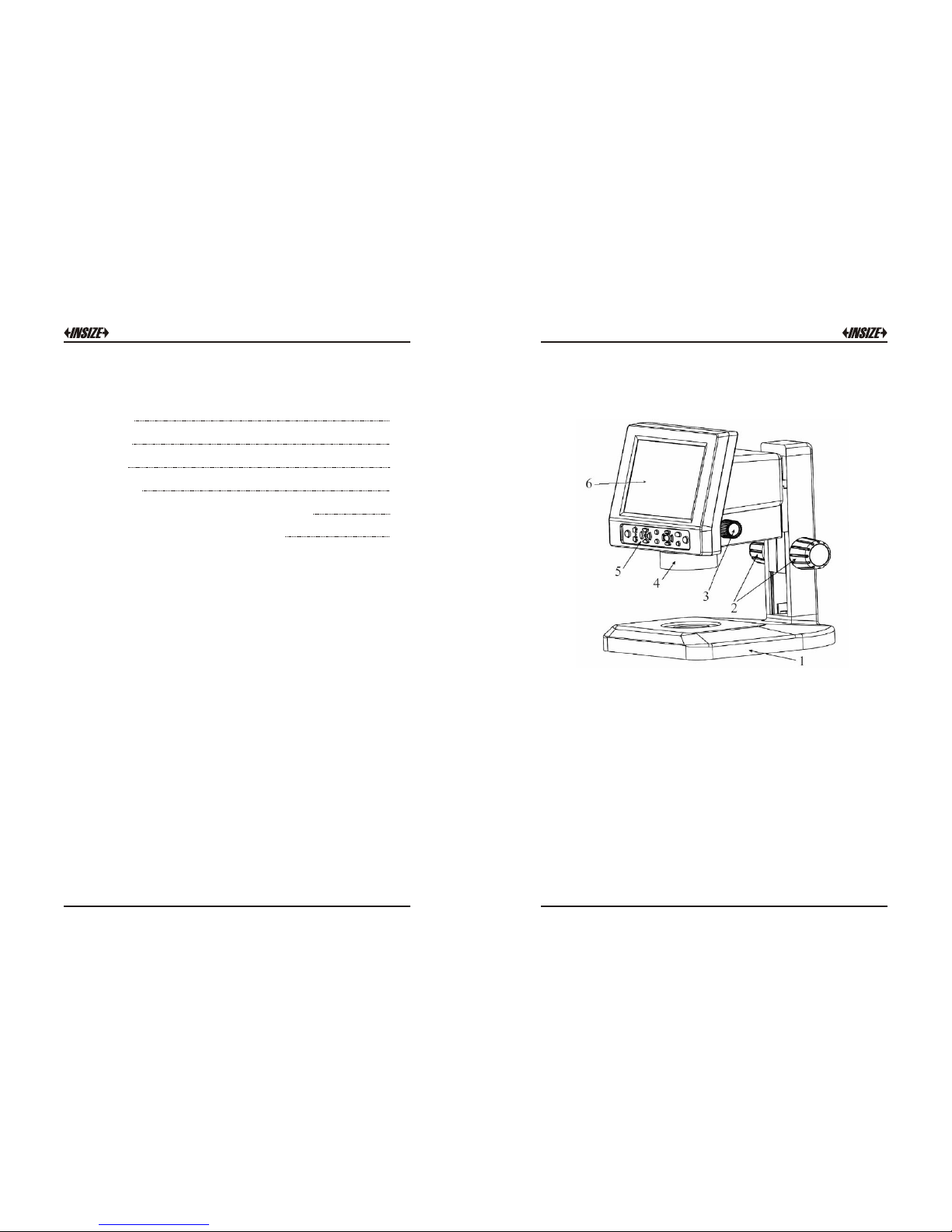
Fig.1 -1 ISM-DL12 0
1. Base 2 . Focus adjus ting hand whe el 3. Continua l zooming
4. LED Ri ng lamp 5. Oper ation butto n layout
6. The liq uid crystal di splay screen
1.2 Description
The digital liqu id cryst al microscope is a one of a k ind opti cal
gauging instrume nt. I t inc ludes a wid e fie ld of vision, 3.14
megapixe l image s, high resol ution l iquid cryst al disp lay. It offers
comfor tab le viewing , s imple o per ation, con venient arch ivi ng,
microscopic imaging and video, as well as many other functions.
Although t he rang e of use is broad, the main ap plica tions a re as
follows:
1. Using rectangular coordinates to determine length. For example
basic planar distance, hachure width ,keyboard trough width, slit
width and so on.
Page 3
The rotation disk determination angle. For example the calibrated
dial, the model, the gauge, the drill hole template and the
geometric shape complex components of angle measurement.
Serves as a microscope, working with su perficial quality by the
compar ison test inspe ctions, t he appraisal of me tallurgical
indust ry ore specimens. The printing of photography allows for
lithog raph plates of examination textile fiber s and so on.
3 4
2.
3.
1.3 Mainframe technical parameters:
1.3 Mai nframe te chnical
param eters:
1: 6.5 (0 .7×-4.5×)
Total magni ficatio n
18.7×-120 × ( 4.7×-240 × can be
obtained with varied accessories )
Digit al amplif ication 1.0×-4 .0×
Displ ay screen
8.4 inc h TFT LCD ( displ ay screen
resol ution 800×6 00 pixels )
CMOS se nsor 3.0 MEG A pixe ls
Worki ng distanc e 88mm
Size of f ield visu al 4.4 x 5.7 -27.2 x 35
Zoomi ng mode
Transv erse axis co ntinual
magni ficatio n change
AC adap ter
100-240 V / 5 0-60 Hz the wor king
power o f the mainf rame: 12VD C 3A
Auxil iary lens 0.5X Oc ular, 0.75X a uxiliary L ens
Illum ination LED rin g light
Ⅱ. Installation
The ISM-DL120 host and its support are disassembled for packaging.
Please open carefully the packing box and take out the instrument
and accessories (for detail, refer to the packing list). Then, connect
the dove-tail groove at the rear base of the machine with that at the
upright column prior to the next step operation.
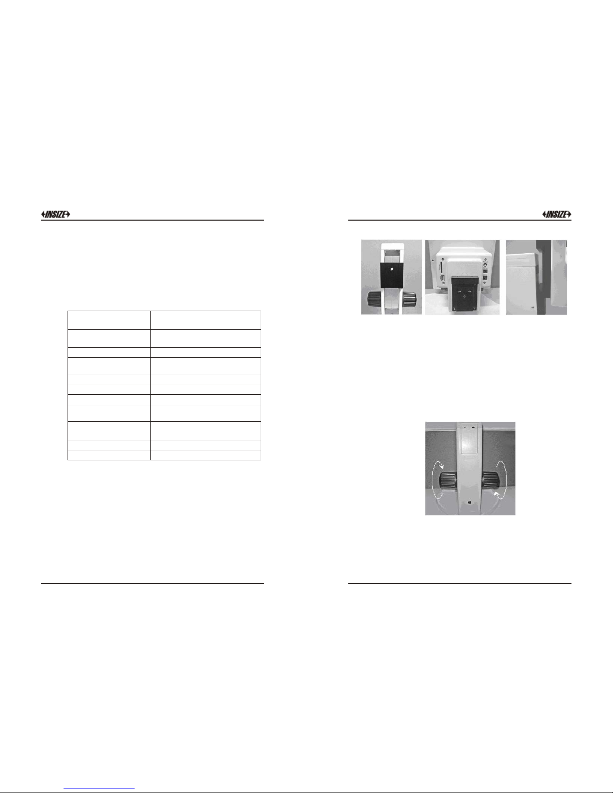
2.1 Installation
The dov e-tail groo ve on
trest le
The dov e-tail groo ve on
mainf rame
Conne ct the dove-t ail
groov e together ta ble
2.2 Attention
Durin g i nstallation, it is not allowed to touch the surface of the
optic al parts and the surface of L CD screen directly with hand.
The image qualit y may be affected i f the optical kits are stained
with figure print or greasy stain. As to the dirt on the su rface of
optic al kits and LCD screen, please carry out treatment according
to maintenance of instrumen t introduc ed.
2.3 Preset adjustment
Select the ope rati on dis tance of the machine by rotatin g the
focusi ng h and whee ls. The tigh tness of focusi ng h and wheels
may be adjuste d thr ough left/ri ght focusi ng hand wh eels by
hands in inverse dir ection. The focusin g resi stance is rat her
strong if it is too ti ght w hile the mach ine may e asil y dr op if it is
too l oose . The users m ay adj ust by themsel ves acco rdin g to
the pra ctic al requi reme nts.
Page 4
5 6
Ⅲ. Appl ication
3.1 Turni ng on
After installation, connect the DC output to the “PWR in” port of
the main system, and then connect the AC power adapter in
accordance with the requirements. Turn on the master power switch.
LED ring lamp will light, mainframe enter the system, the screen
show “WELCOME”.
The pow er of the ada ptor: 100- 240V AC 50Hz/6 0Hz
The mai nframe wo rking powe r: 12V DC 3A
The lig ht source a dopts LED ri ng
lamp, divide d into th e LED cir cular
indic ator wi th adju stable b rightne ss
and th e multipl e functio n LED circular
indic ator cont rollable a t four zones .
The lower light source is opt ional on
requi rements to fac ilitate observa tion
of diff erent obj ects. The l ower ligh t
sourc e is su pplied by the P WR out at
the rea r of the mach ine by conne cting
the PWR o ut of the ma chine and t he
input p ort at the u pright column with a
conne ction lin e.
3.2 Ope ration bu ttons and fu nction
1 2 3
4
5
6
7
8 9
1. Powe r on/off 2. Incr eases or decre ase the bright ness of lamp
3. Ligh t switch resp ectively to c ontrol the fou r-region on or o ff
4. Self -definiti on linear con verting
5. Line ar color conv erting 6. Men u / confirm 7. Rea l time view / play back
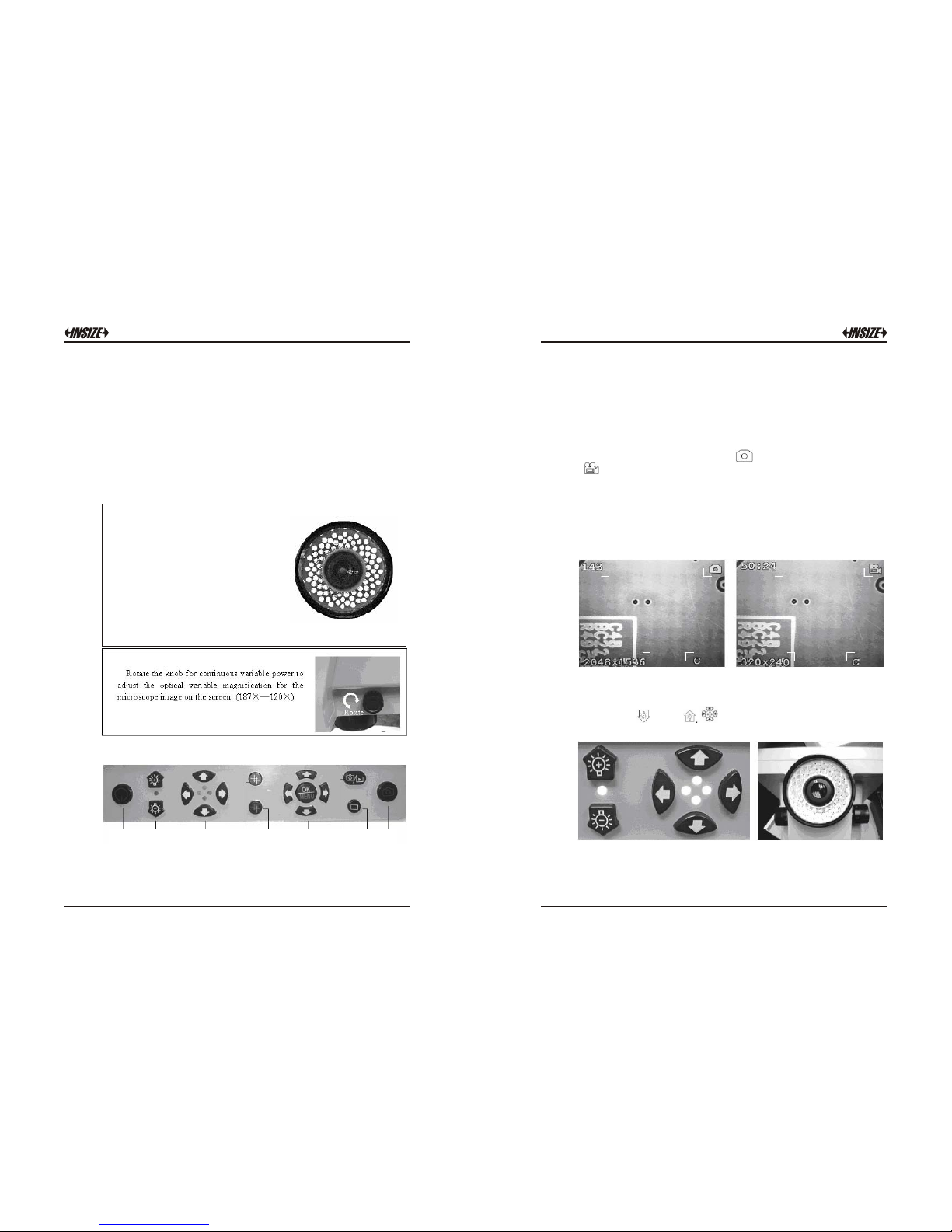
8. Scre en data displ ay 9. Take pi ctures or tak e video
Shown on the u pper left corner is the quantity of photos to be
taken avai lable at present or the vide o recording time (with 143
indicating 143 photos availab le to betaken at the present setup
mode; 50: 24 i ndicati ng the time f or video reco rding at th e
present se tup mode as 50min 2 4sec).
3.3 Data show on the LCD scree n
Shown on the uppe r right cor ner is the mo de of photo taken
or the mode of video recordi ng.
Shown on the lower left corne r is the pixels of photos t aken (
2048×1536 i ndicati ng th e pixels for p hoto taken at the present
setup mod e as 2048×1536; 320×240 indicating the pixels for
video re cording at the present setup mo de a s 320× 24 0).
“C” sh own on the lower right corn er means that S D card is
inserted in th e mac hine
3.4The illumin ation con trol of the m ainframe
The br ightne ss of LED lamp may be increased or decr eased wi th
the h elp of and , is respectively used to turn on/off
for th e corres pondin g four corners of LED indicator.
If the li ght throw back from the object is too sharp, user can instal l
a ground glass on th e LED ring lam p. It can improve the image
quality. (This ground glass nee d to order)
Page 5

7
8
may be used to select self-definition graphics, including the
cross line, coordinates lattice, carrying out simple locating and
measurement.
On the micro- ruler is calibrated with precise gradua tions of three
kinds, i.e. 0.1mm, 0. 01mm and 0.05mm respectively. Prio r to the
measurement of the o bject, select f irstly the coordinate or lattice
for the self-definition graph. Then, select a certain gra duation of
micro-ruler under the digital LCD microscop e. After having clear
focusing, es timate the separation of the coordinate or lattices by
comparing t he separation of coordinate or l attice with the
distance of the st andard graduation. Under the condition n ot to
change the power, observe the object inspected. After having
clear focusing, user can estimate the length or size of area for
the object.
3.5 Self-definition gr aphics
3.6 How to measure
May be used to select among colors of the self defin ition
grap hics, facilit ating the clear i ndicat ion under different col or
mate rials.
Select the stan dard gradua tion of 0.05mm un der a given power
and move the micro -ruler after having clear foc using so that
the coord inate corresponds with the micro-ruler. The standard
ruler o f e very 12 gradua tions corre spond to 19 graduations of
the coo rdina te ruler, then, each graduation of th e coor dinate
ruler is about 0.03m m(12 0.05/19). In this case, user can
carry o ut the m easurement for the object observe d u nder
micro-sco pe a cco rding th e di sta nce of coordi nat e ru ler
(requirin g re-calibrat ion of the separa tion of coordin ate ruler
each time for a chang ed power).
Exampl e:
3.7 Selection of functio n menu
With the help of the function menu, it is available to carry out the
setting for the whole system. It is available to select the following
functions through right/left key:
Page 6

9 10
A. Photo taken mode
B. Image Setting
C. Image Size
D. Date and time
E. TV Out
F. Frequency
Press the Up/down keys when the system is on the real time view
station. It can digital zoom the image from 1.0X to 4.0X. This digital
zoom function can help user have a more clear view.
3.8 Digital Zoom functio n menu
3.9 Take phot o and photo m anagement
Select sing le photo at the photo taken mode me nu and pr ess the
photo takin g button, the system wil l save a ph oto.
At the photo taking mode menu and select the video 320X240,
press the photo taking button to star t AVI video recording. Press
the photo taking button once again to stop the AVI video recording.
When the SD/MMC card memory is full, the system will show
“Memory is full”.
Page 7

11 12
As to the photo or video, it is available to change over to real time
mode or playback mode for the shooting information with the help
of . At the mode of playback, it is available to delete single photo
or to delete all the information. With the microscope placed at the
mode of playback, it is available to use USB connection line to
transfer the data to the computer.
At the playback station, with the help of the function menu, it is
available to carry out the setting as following:
3.10 Rear input / output por ts
①. it is available to connect through AV Out port of the microscope
image to the Monitor in real-time.
②. Power Out is a power supply port to connect the bed light source.
③. Power In is a connecting port for the main system power supply.
(12VDC 3A)
④. SD/MMC port is an interface to insert SD memory card.
(Warning: Before pull out the SD card, please turn off the system)
⑤. USB port is used for the data communications.
3.11 USB da ta commun icate
when the system is on the playback station, use USB connection line
to transfer the data to the computer.
When the system is on the real time view station, use USB connect
the computer. It can view the real time image in the computer by
software.
The Screen show after connect the Open the software “Im pression 4”
computer
Page 8

13 1 4
Cho ice the c amera i tem, se lect th e Use the c omput er to vie w the ima ge
format of the image to view the image
For model ISM-DL120 machine, a software disk is provided and the
function is available after installa tion of the two programs from the
disk (Install Photo Impression, Install Driver).
A clearer image may be obse rved from TV set via AV output
since there is limit of pixels on the L CD scree n (800X6 00).
Similarly, the pixels of photo taken with the micro scope may
reach 2048X1536 , an d the image will clearer under photo
playback mode or when obse rving pho to from the computer after
transmission.
3.12 Image view
Ⅳ. Maintenance
For the sake of good micro scope protec tion, it is requ ired to a void
dust, water and humidity intr uding into the instrument, otherwise,
the photo r oute and the elect ronic circ uit of microscope might be
damaged. Moreover, t he apparent grease sp ot, finge r pr int on the
surface of o ptica l kit, dus t, d irt stains will e ffect t he imag ing
quality.
When the microscope is not in use, the micro scope should be
cover ed with a clea n sheath timely to prevent dust from entering i n.
The product is suitable for application and storag e indoor, with the
environ-mental humidity for ope ration and sto rage being 30%-
80%. The environmen tal temperature for operation and st orage being
0°C-40°C.
Optical section
The lens should be sto red in a d ry environment, and it i s availa ble to
place it in a containe r with dr ier agent.
If the surf ace of lens is attached with dus t, ple ase us e an air blower
ball to cle ar it o ff.
If the surface of lens is attached with finger print, dirt, greasy stain
or other trace not available to use an air blower ball to clean, please
use absorbent cotton or lens paper dipped with a little alco hol or ether
mixture (proportion 1:4) to wipe off them li ghtly.
Notice: Un der no any circumstances sh ould th e lens surface be dry
cleaned, otherwise the surface of lens may be damaged.
Moreover, it is not allowed to wipe the lens with water or other
liquid solutions.
It is requ ired to pay attenti on tha t no heavy pressure on the surface
of color L CD screen is allowable du ring operation and storage.
LCD screen
In case the LCD screen surface is dirty, it is only available to use
clea n and soft cloth to wipe lightly, and it is forbidden to us e organ ic
solu tion ag ent to wash an d clean .
It i s forbidden for t he con sumers to disasse mble the microsco pe by
themselves, lea st the re is dange r of d amage or electric shock .
Page 9

15 1 6
A. Installation method a nd steps of t he micrometer:
★ Plug ② s upport rod of micromete r in to
① mova ble plat form cla mp sprin g first ,
with the LCD sc reen fa cingupwar d, and
notin g t hat the support rod of microm eter
shoul d be plugged to locat ion. Then, use
M3 i nner he xangula r spann er to ti ght
unifo rmly the faste ning screw for th e rod
of mi crometer to the ex tent of no t shedding
off an d rotating the micro meter.
★ I nstall another micromet er in the same
way and steps t o the movable platfo rm
clamp spr ing. Tighten the fast ening screw to
clamp the sup port rod of micr ometer to the
extent of no t sheddi ng off and not rotating.
Put it into the bla ck/white w orkbench or
single sided frosted glass wo rkbench (note
that the smo oth surface shou ld be facing
upward ). The final install ation structure is a s
shown in th e diagram.
Ⅴ. Installation and Operatio n Man ual o f Ima ge Tester
B. The con nec tion a nd ap plicati on of b ed lig ht so urce:
★ The co nnection of bed light so urce:
Connec t one end of the connect ion line with
the both e nds having spri ng and normal D C
specif ication to the DC socket ma rked with
"DC OUT", with another terminal inserting
into the DC so cket of the frame.
★ Adjust the blac k knob for the bright ness
of bed lig ht source, atta ining the sharp
image outline. The arrowhead direction i s
the rota ting d irect ion fo r inc reasi ng
bright ness. The re verse direc tion is for
bright ness atten uating an d turning off the
bed light so urce power.
C. Opera tin g inst ruc tions for t he me asur eme nt applic ati on of
image te ste r:
Place t he system levelly on a desktop. Firstly, install and
fasten the micromete r and the m ovable platform, wi pe clean
the workbe nch surface, connect properly the DC con nection
line of bed light sour ce, an d connect the main system power
supply.
Press lightly the main system power switch, start the
instrument and rotate the rapid driving dev ice o f micrometer
so that the screw rod of the micrometer stretches out ab out
half of length (12.5mm). Place the substance to be measured
lightly on the center of workbench surface, with the bed light
source available to shine thoroughly for the best.
Adjust the focal length, magnification and the brightness of
the upper light source and the bed light source, making the
substance to be measured having a very sharp image.
Self define the linear graphic, rotate the rot ary disc of the
rotation movable platform, so that one side of the substance
tested runs par allel wit h the cross line. R otate aga in the rapid
driving de vice of micrometer to a lign closely one s ide of the
substance tested with the cross line. Reset the micrometer.
Rotate the ra pid driv ing devi ce to align closely the position to
be measured with cross line of one side of the aligned
substance. The value of the micromete r is the value of the
substance value mea sured.
★ The measurement of leng th:
1.
2.
3.
4.
Remarks: The detail application of the micrometer is referred to
the operation manual of the electronic micrometer.
Page 10

17 1 8
Ⅵ. Operation Manual of Electro nic M icr ome ter
1. Sketch diagram of struc ture:
1). Screw rod
2). Link rod
3). Data output key
4). Fast driving device
5). ON/OFF…SET key
6). ABS/INC…NIT key
7). LCD screen
8). RS232 data output port
9). Battery cover
2. LCD screen:
IN: The prompt sign for indication of
English system measurement mode
Set: The prompt sign for indication of
initial value setting INC: The prompt
si gn f or i ndi cati on of rel ati ve
measurement mode : The prompt
sign for under voltage alarm indication
of battery ABS: The prompt sign for
indication of absolute measurement
mode : The prompt sign for
indication of data output status
3. The fu nction an d operation of the key:
There are two kinds of key ope ration:
(1) Short press (time < 2 seco nds)
(2) Long press (time 2 secon ds)
3.1 ON/OFF…SET: The swit ch key, delay setting ke y
The key operation < 2 seconds: Power supply ON/OFF of digital
display meter
The key opera tion 2 seconds: Setting in itial valu e of digital
display meter of a bsolu te measurement: Display "Set" .
After reinstalling a battery, the initial value setting will be carried
outautomatically.
The default initial valu e of the digi tal display meter is 0.
The data output key:
The key operation < 2 seconds: It will deliver output once, and it
will display on the LCD screen once as " ".
Continuous key operation ≥ 2 seconds: It will deliver output
display dat a continuousl y, and the LCD screen disp lays
continuousl y " ".
The output data will be ended if you press this key again.
ABS/INC… UNIT: Absolute/relative measurement mode convert
key, the delay metric system/English system to measurement
mode convert key. The key operation <2 seconds: Absolute
and relative measurement mode convert: Relative measurement
mode with "INC" indication, absolute measurement mode with
"ABS" indication. The key operation ≥2 seconds: Metric/English
system convert: The English system measurement mode with
"in" indication, otherwise it is the metric system measurement
mode.
3.2
3.3
Digital display meter adopts on e SR44 battery. Please replac e
the battery when th e digit displa yed on LCD screen is unclear
or when display ing " ".
The digital display meter will cut off the power automaticall y if
the digital display meter is n ot u sed for 5 minutes and it will
resume to the origin al value prior to the auto cutt ing off if
rotating the screw rod or pr essing "O N/OFF… SET" key.
Please press "ON/OFF…SE T" key to turn off the p ower supply
for energy saving if it is not t o be used.
Insert a c oin to the slot on the battery cover and rotat e
clockwise to lose and open the batter y cover. Take out the
used battery.
Change for a new battery with the positive polarity heading
up. Screw tightly the batt ery cover a nti- clockwise.
4. Power su pply:
≤
≤
Page 11

19 2 0
The data output is of t he st andard RS232 C format, and can
be connected to the serial P C port via ca ble.
5. Th e data output:
6. Precauti ons:
Do not fall off or co llid e the digit al displa y me ter and d o no t
app ly too gr eat a force.
Do not dism antle t he digital display m eter.
7. Characte ristics :
Measurement of force: 5-10 N measuring range: 0-25 (the present
product supplied)
resolutions: 1µ m
Power consumption: ≤ 35 µA operation temperature: 0-40°C
storage temperature: -20 - 60°C
Do not press the key with a sharp object. To press a key, please
move along the moving direction of the key, otherwise, it will
affect the sensi tivity of key.
Please do not use or store the digital display meter at a location
with direct sunlight, or an environment too cold or too hot.
Please do n ot use the digital d isplay meter in an environm ent
with too hi gh volt age or strong magnet ic field.
The dry soft cloth or cotton may be used to wipe the stains on
the surface of digital disp lay meter. Do not use organic solvent
such as acetone or benzene to clean the meter.
Use soft cl oth to wipe the meas urement face before
measurement.
Pleas e take out the battery if the meter is not to be used for a
long time.
8. Trouble sh ooting:
Sympt oms
The LCD s creen
displ ays "E 1".
The LCD s creen
displ ays "E 3".
The meas urement
value is no t
accur ate.
The LCD s creen
does no t display.
The displayed digit
is not stable, not
clear; The displayed
digit is not changing
or is confused.
Possible ca uses
The compute r data
overflow.
1. Interference exists
in t he peripheral
environment. Perhaps
the sensor is stained
with foreign object to
result in a mistaken
sensor.
1. Measurement face
may be dirty.
2. The setting value
may be not accurate.
1.T he battery installation
is incorrect.
2. The battery may be
short of capacity.
1. Battery voltage is
possibility less than
1.45V.
2. The battery installation
may be incorrect.
Remedies
Move the screw rod
in re verse direction
to resume the normal
displ ayed value; Or
press ON/OFF…SET
key to set up again
the initial value of
measu rement.
1. Reinstal l the
Battery.
2. Send bac k to the
factory for repair.
1. Wi pe the
measurement f ace.
2. Ch eck the setting
value, and set up
again.
1. Reinstal l the
battery.
2. Replace the
battery.
1. Replace the
battery.
2. Reinstal l the
battery.
2. The senso r breaks
down.
 Loading...