

Page 1

www.insize.com
MN- ISH- PHB-E
ISH-PHB
PORTABLE HARDNESS TESTER
OPERATION MANUAL
Page 2
Attention
Description
Don’ t imp act without mea surement and cali bration , oth erwise the
impa ct device may b e damaged .
Plea se r eading the oper ation manual care ful before usin g, m ake
sure the weight, thi ckness, surface rough ness of t he workp iece
are me eting the req uiremen t.
Plea se do calibr ation w hen u se the device first time or int erval for
a long t ime.
Clea n up the rusty, oil on t he surface be fore meas ure.
The distance between any two impact position should be ≥3mm. the
distance between impact position and the edge of the sample should
be ≥3mm.
Make the su pport ri ng stick to and
keep t he impact dir ection pe rpendic ular to
Keep work piece and impact device steady dur ing
ope ra tor,
the sur face of the workpiece
the su rface.
meas urement .
1
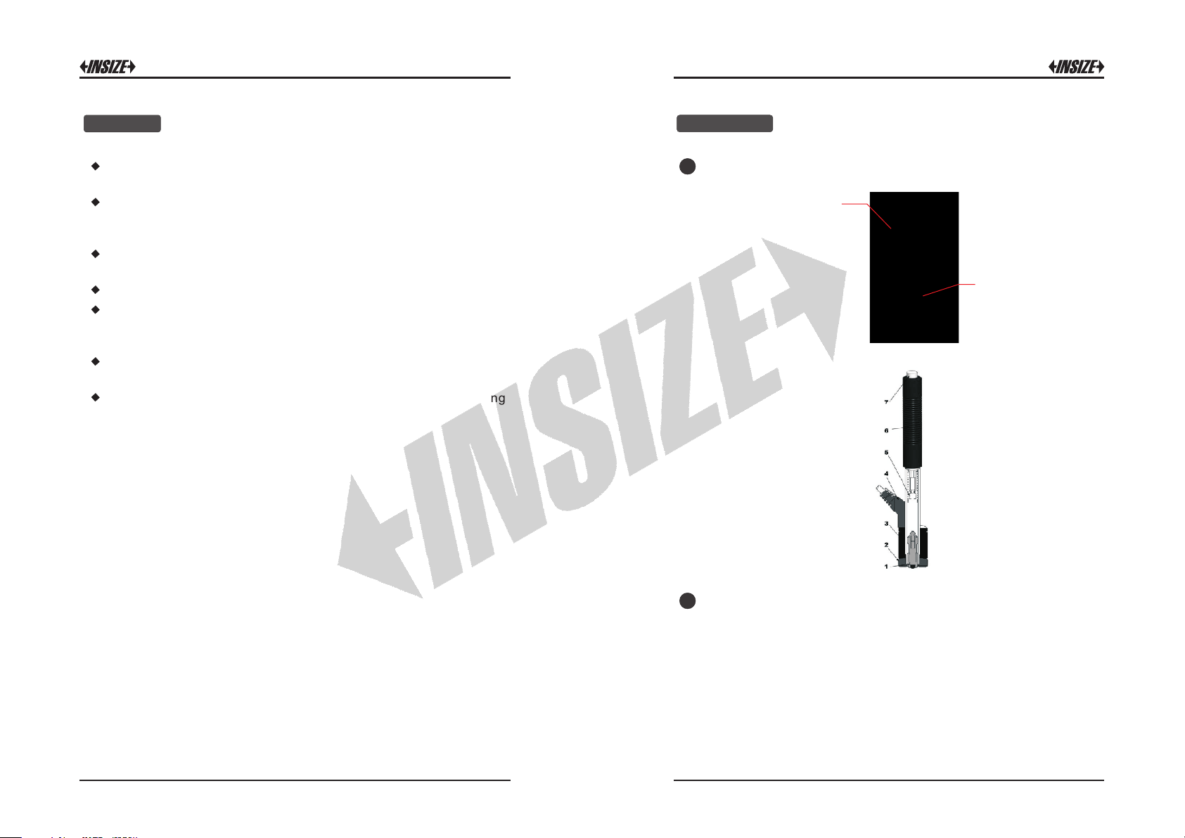
Stru cture:
LCD Display
Butto n
Main unit
1.
Impac t bo dy
2.
Support r in g
3.
Coil
4.
Cable
5.
Catch c hu ck
6.
Loading t ub e
7.
Release b ut ton
Impact device
2
Workin g principle :
Push down the loadi ng tube befo re meas urement, the c atch
chuc k catch u p the i mpact bod y. Make the support r ing sti ck to the
sur face of the work p iece and kee p the imp act dire c tion
perp endicul ar to the s urface. The n press t he releas e button, the
impa ct body wi ll impa ct the surfa ce. The c oil col lect th e veloc ity
sign al and the ca ble transmi t the dada to the m ain unit.
1 2
Page 3

3
Specification:
Disp lay range : 0 999H LD~
Accu racy: ±6HLD (when HLD = 800)
repe atabili ty: 6H LD±
Impa ct directio n: 0 °, °, 180 °, °, °±90 ±45 ±135
Conv ersion sc ales: HV, HB, HRB, HRC, HV, HSD, MPa
4
Button function:
5
LCD display:
HLD val ue
Imp ac t and s tat is tic t ime s
Mater ial c ode
Imp ac t dir ect io n
Dat e and tim e
HLD ave ra ged v alue
Conve rsi on val ue
1
3
1. On/Off b utton : Turn it o n/off by press ing and ho lding the
butt on.
2
4
5
2. Up ar row button :
① In me asureme nt m ode, pres s this button t o select
conv ersion sc ale.
② In mea surement m ode, pre ss b utton to delet e curr ent
resu lt and pres s th is button t o confirm.
3. Set up button :
① In measur ement mod e, press this butt on to s elect the items
need to be set like sta tistic tim es, ma terial cod e, date, time,
etc.
② Turn off the mach ine, pres s this bu tton and On/Off button
toge ther to enter c onversi on value cali bration .
4. Ret urn button :
① Back t o measureme nt mode.
② Turn off the mach ine, pres s this bu tton and On/Off button
toge ther to enter L eeb value c alibratio n.
5. Down arrow butto n : In measure ment mode, press this
butt on to enter dat a browsin g mode.
Leeb Value Calibration
Plea se do calibra tion when use t he d evice fir st t ime or interv al for a
long t ime.
Note: Please do calibration with standard test block in packing box.
1
Pres s setup but ton then set me asuring c onditions b y using up an d
down bu ttons, select material code to numb er 01, the i mpact
dire ction is do wn. Turn off the machi ne after do s etup.
2
pres s rut urn b utton and On/Off button toget her ( about 2 seconds)
to e nter Leeb v alue ca libration , the INS IZE logo will blin k on top
left corne r. Meas ure 5 t imes on t he surface of s tandard test
bloc k(you should do en ter c alibrat ion mode again if get any val ue
whic h deviati on is large).
3
Inpu t the actua l HLD value of the t est block by use u p and dow n
butt ons, then pre ss return b utton back to m easurem ent mode.
Note: The distance between any two impact position should be ≥3mm.
the distance between impact position and the edge of the sample
should be ≥3mm.
Conversion Value Calibration
This calib ration is appl ied to some workpiece you don’t know the
Leeb h ardenes s but only conv ersion ha rdness valu e like HB, HV, etc.
Note: Please do calibration with known hardness workpiece.
1
Pres s up arrow button to se lect t he con version scale , then Press
setu p button then s et measur ing conditi ons by usin g up and down
3 4
Page 4
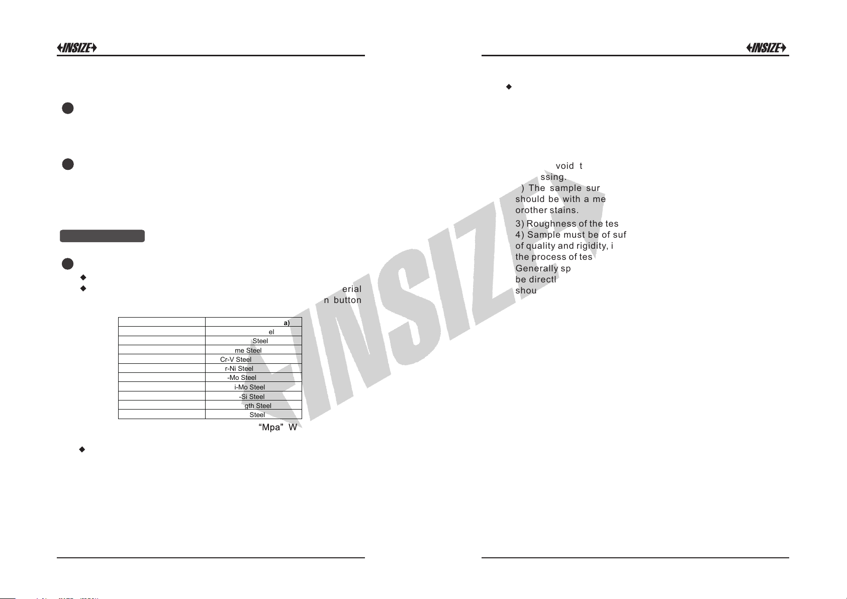
butt ons, sele ct right mate rial code , the impac t directi on is down.
Hardness Tensile strength (MPa)
01.Steel and Cast Steel 11. Low Carbon Steel
02. Alloy Tool Steel 12. Hi Carbon Steel
03. Stainless Steel 13. Chrome Steel
04. Grey Cast Iron 14. Cr-V Steel
05. Ductile Iron 15. Cr-Ni Steel
06. Cast Al Alloys 16. Cr-Mo Steel
07. Cu-Zn Alloys 17. Cr-Ni-Mo Steel
08. Cu-Sn Alloys 18. Cr-Mn-Si Steel
09. Copper 19. Hi Strength Steel
10. Forging Steel 20. Stainless Steel
Tur n off the machine a fter do set up.
2
pres s setup b utton an d On/Off butt on toget her (about 2 second s)
to ent er conver sion value ca librati on, the INSIZ E logo will b link on
top l eft corner. Me asure 5 tim es on the su rface of wo rkpiece (y ou
shou ld do enter calibra tion mode again if get any valu e which
devi ation is la rge).
3
Inpu t the a ctual v alue of wo rkpiece by u se up and down bu ttons
then p ress return b utton bac k to measurem ent mode.
Note: The distance between any two impact position should be ≥3mm.
the distance between impact position and the edge of the sample
should be ≥3mm.
Measurement
1
Prep aration b efore measu ring:
Tur n on the mach ine.
Pres s setup button and set statisti c times, select the mat erial
code accordi ng to the back label, then pre ss retur n button
back t o measureme nt mode.
Note: The value can only convert to “Mpa” When select the
material code 11~20.
Pres s up arrow bu tt on to selec t right conve rsion sca le.
Note
:
1. The conversion value is “---” indicated the conversion is out of
range.
2. Conversion value only supplies the general reference, which
may result in some offset. Precisely conversion generally needs
related comparative tests.
Samp le Prepar ation:
Inap propria te sample will cau se a grea t m easuremen t erro r.
Ther efore, users should make the necessar y hand ling and
prep aration u nder the orig inal cond itions of sam ple.
Prep aration of the sa mple and th e s urface of tes t s hould be
coin cident wi th the follow ing basic r equiremen ts:
1) Dur ing the pro cess of sam ple surfa ce pre paratio n, u sers
shou ld avo id the imp acts of cold p ro cessing and the rmal
proc essing.
2) The sample surface is plane for bett er, the test sur face
shou ld be with a m etallic sh een, and not invol ve oxide laye r
orot her stains.
3) Rou ghness of the t est surfa ce Ra ≤ 1.6
4) Sample must be of su ffic ient quality and rigidi ty. If i t's la ck
of q uality an d rigidit y, it may caus e displac ement or shaking i n
the pr ocess of test ing impac t, which can le ad to large e rrors.
Gene rally spe aking, if the s ample qua lity is more th an 5kg can
be di rectly tes ted; if the sample qua lity is 2~5 kgs, the sample
shou ld b e taken in fixa tion test b y means of appr opriate
clam ping; if t he s ample quality i s 0. 1~2kgs, the sam ple
shou ld be c onducted coup ling bef ore th e te st; if the sampl e
qu a l i t y i s l e s s t h an 0. 1 k g , t h i s h a r dn e s s t e s t e r is
inap propria te to use.
Coup ling meth od: Testing sam ple's back should be p repared
to make a pl ane as a sup porting surf ace wit h a s mo oth
form ation. Fi lling with a li ttle coup ling substa nce (Indu stry
Vaselin e can b e used), users can no w pres s to th e surf ace of
the sup porting obje ct (The weigh t of sup porting ob ject should
be mor e th an 5 kg, and it ca n be rep laced by test block) to
stic k into integr ation.
5) S amples sh ould be t hick enou gh and wi th sufficie nt surfac e
abso rption layered. If users use D-t ype im pact device, the
thic kness of sa mple should n ot be less th an 5mm, and sur face
abso rption layer (or surfac e-hardeni ng laye r) s hould not b e
less t han 0.8mm. To accurat ely measure t he h ardness o f th e
mate rial, the best way is to remove the surfa ce-harden ing
mate rial, the best way is to remove the surfa ce-harden ing
laye r by proces si ng.
6) When test ing s ample surf ace i s not ho rizonta l, th e
curv ature radiu s of testin g and nearby su rface sho uld be
5 6
Page 5

larg er t han 30mm. And approp riate suppo rting ring shou ld b e
elec ted and ins talled.
7) A s ample should not be with magnet ic. The signal of the
impa ct device wou ld be serio usly inter fered in the w or k by the
magn etic, whi ch m ay cause in accurate te st result s.
Meas uring Ste ps:
2
Load ing: S imply load the impact devic e by sliding the loadi ng
tube f orward.
Plac e: Then pla ce and hold the impact device on th e surface
of the test piece at the desir ed test p oint. Impact ind irectio n
shou ld be verti ca l with the te st of surface .
Burs t imp act (Measure ): Trigger the impact by pres sing the
rele ase butt on. The har dness va lue will be insta ntaneousl y
disp layed.
Read o ff t he test resul t from screen .
Note : Gene rally, ea ch measu rement l ocation of sam ple is
cond ucted f or th e five tests . The “ S” (diffe rence o f maxim um
valu e and minimum va lue) value s must be less than 15 HL.
The d istance between any two impa ct posit ion shou ld be ≥3
mm ; the d istance b etween impa ct positi on and the ed ge of the
samp le should b e ≥3 mm.
3
Memo ry:
The data group (suc h as test resul t, conversio n res ult, sample
mate rial an d impac t directi on) aut omatica lly save in memo ry afte r
one i ndividu al measure ment. IS H-PHB ha rdness tes ter can s tore
99 sets of data, when measuring times more th an 99, the las t
grou p of data will store the 99th po sition an d the fir st grou p of
data wil l be erase d. The second grou p of data will be moved into
the 2th position, simult aneously the position of oth er group of
data , will be mov ed into lower p osition .
Pres s down arro w button to enter me mory stor e mode, u se up and
down b uttons to bro wsing the m emory.
4
Prin t (the printe r is option al):
Afte r on e set meas urement press set up butto n an d let the p rint
symb ol blink, n ow press retu rn button to pr int curre nt result.
Maintenance
1
Impa ct Device Mai ntenanc e:
Afte r using 10 00-2000 ti mes, us ers s hould c lean the cat heter of
impa ct dev ice and impact body wit h ny lon brush, and scre w off
the sup porting ri ng before clean the cath eter, and th en ta ke out
the imp act body, rotate the nylon br ush in to the tube in an anticloc kwise dir ection, and p ull out whe n touchin g the bot tom. S o
repe atedly, and then load up the impact b ody and supporti ng ring ;
User s sho uld rel ease the i mpact body a fter use. And the lubri cant
is ban ned.
Norm al Mainte nance Proce dures:
2
In calib ration of the hardn ess tester, if findi ng t hat error is larger
than 6HLD, u sers m ust be r enew t he s teel b all or i mpact body,
beca use the re ason may be that the s teel ba ll or im pact bo dy is
wore o ut to lead to fai lure in ope ration.
7 8
Page 6

Factors Affection Accuracy
Measuring And Conversion Range
Inco rrect opera tion o r improper te sting condi tions would hav e
seri ous impact on testing accur acy. Follow ing is several common
fact ors effect the ac curacy of tes ting for th e use of refere nce:
1) Rou ghness of sam ple surfa ce
When the impact body impact on th e samp le, a small pit would arise
on the sample surfa ce, s o a t the same time , sho uld f inish the surface
of the sample. The more r oughnes s, the less cons umption of impact
ener gy wherea s the less roug hness, the mo re consum ption of impa ct
ener gy. Acc ordingl y, the rough ness of s ample testing points o n the
surf ace Ra≤ 1.6.
2) The sha pe of sample su rface
Leeb testi ng princ iple deman ds the velocit y of rebound and impac t
are on t he same lin e, because th e impact bo dy is moving in a metal
tube . Even if the ve locity o f rebound and imp act are n ot on the same
line , it also can s how h ardness fo r sur e, but the impa ct bo dy wo uld
coll ide wi th t ube wa ll w hen it rebou nds, which will affect t he v elocity
of rebou nd. Ther efore, a g reater error is on t est ac curacy. W hen the
radi us of curvatu re of the t esting sampl e sur face is smaller, th e
solu tion is the use of suitable var iant suppo rting ci rcle. If users
requ ire special sup porting circ le, we can contribut e to design and
proc ess.
3) The wei ght of the samp le
If the sa mple weight must be larg er than or equal to 5kg, and not
easi ly sway. If the samp le weight w ere less, the s ample wou ld need
prop er tr eatment (I t is neces sary to in crease the supp orting or
moun ting th rough coupling comp ress on larger weig ht test ing sta nd),
and the test ing result s can be ac hieved in accur acy. There shou ld be
a certain area at the testi ng po ints (the area require d to meet a set of
test ing points) and no vi bration or shak ing. I f th e we ight i s not
enou gh, users mus t be as much as possib le reduce the ji tter and
slos hing by the method s of i ncreasi ng s upporting , couplin g and
comp ressing . And supporti ng device s hould avoid s hock.
4) The sam ple stabili ty
Any effective test s need to mi nimize possibl e inter ference from
outs ide; it's more impor tant to dynamic me asure such as Leeb
hard ness test. T herefore, meas uring only allowe d in stabl e har dness
test ing system. If it's lik ely to l ead to s ample movem ent in t he t ests,
user s should fi x it b efore tes ting.
HLD
HV
Materials
Steel & cast steel
Tool steel
Stainless steel
Cast iron
Cast aluminum alloy
Brass
Bronze
Copper
300-900
300-840
300-800
360-650
170-570
200-550
300-700
200-960
81-955
80-898
85-802
HB
HRC HRB
-68 38 -100
20
81-654
20-67
85-655
85-655
93-334
93-334
19-164
19-164
40-173
60-290
45-315
47-101
23
13-95
HS
32 -100 375 -2639
-84
Standard Delivery
Main unit
Impact device D
Hardness test block
Small support ring
Cleaning brush
1pc
1pc
1pc
1pc
1pc
Optional Accessory
Support rings
Wireless printer
refer to our catalogue
ISH-DS-PRINTER
Tensile
strength(Mpa)
9 10
 Loading...