

Page 1

www.insize.com
MN- ISH- PHA-E
ISH-PHA
PORTABLE HARDNESS TESTER
OPERATION MANUAL
Page 2
Attention
Description
Don’ t imp act without mea surement and cali bration , oth erwise the
impa ct device may b e damaged .
Plea se r eading the oper ation manual care ful before usin g, m ake
sure the weight, thi ckness, surface rough ness of t he workp iece
are me eting the req uiremen t.
Plea se do calibr ation w hen u se the device first time or int erval for
a long t ime.
Clea n up the rusty, oil on t he surface be fore meas ure.
The distance between any two impact position should be ≥3mm. the
distance between impact position and the edge of the sample should
be ≥3mm.
Make the su pport ri ng stick to and
keep t he impact dir ection pe rpendic ular to
Keep work piece and impact device steady dur ing
ope ra tor,
the sur face of the workpiece
the su rface.
meas urement .
1
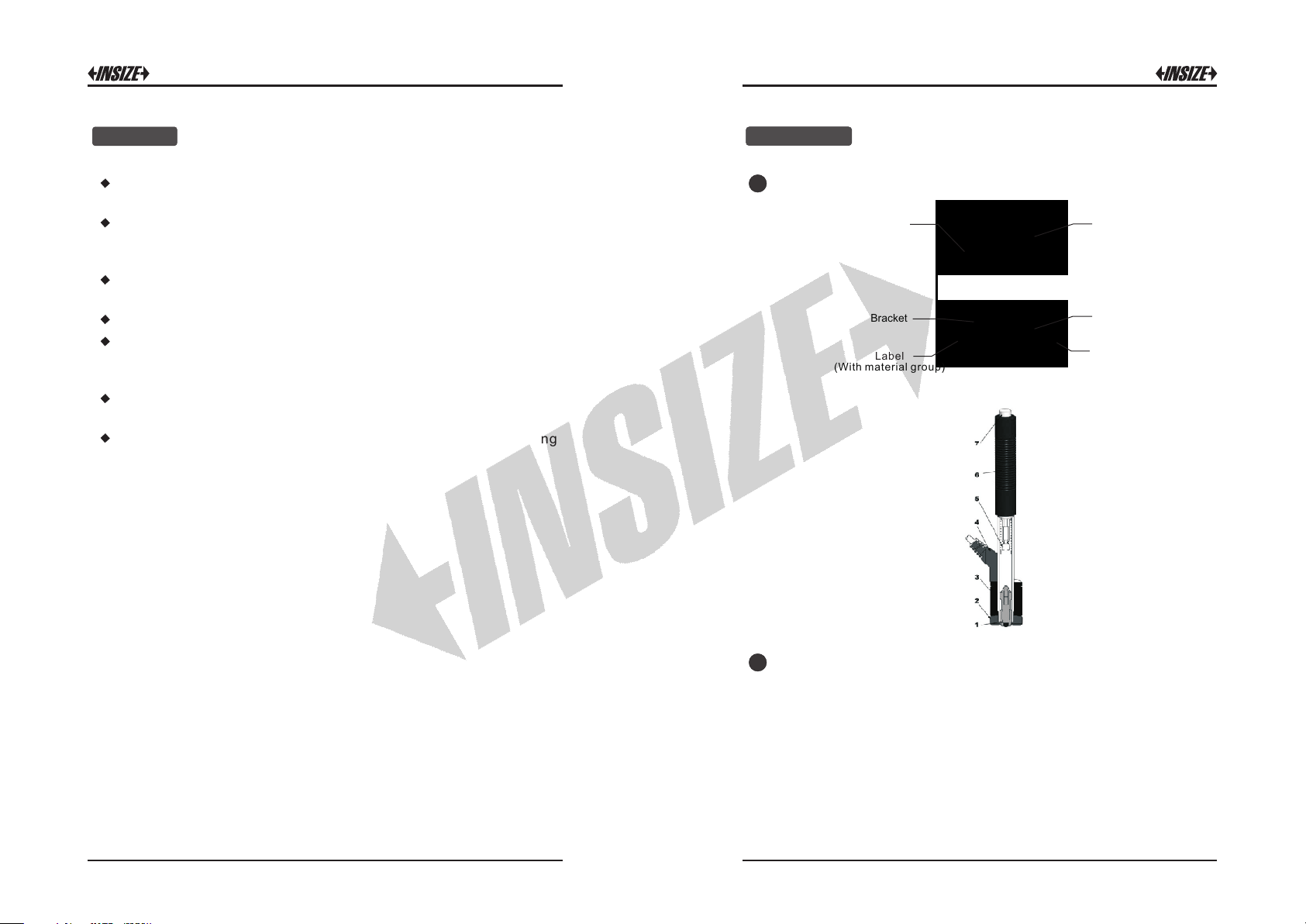
Stru cture:
LCD Display
(With m at er ial gro up )
2
Workin g principle :
Bracket
Label
1.
Impac t bo dy
2.
Support r in g
3.
Coil
4.
Cable
5.
Catch c hu ck
6.
Loading t ub e
7.
Release b ut ton
Main unit
Impact device
Butto n
Cell Cove r
Signal Ca bl e
Push down the loadi ng tube befo re meas urement, the c atch
chuc k catch u p the i mpact bod y. Make the support r ing sti ck to the
sur face of the work p iece and kee p the imp act dire c tion
perp endicul ar to the s urface. The n press t he releas e button, the
impa ct body wi ll impa ct the surfa ce. The c oil col lect th e veloc ity
sign al and the ca ble transmi t the dada to the m ain unit.
1 2
Page 3
3
Specification:
Disp lay range : 0 999H LD~
Accu racy: ±6HLD (when HLD = 800)
repe atabili ty: 6H LD±
Impa ct directio n: 0 °, °, 180 °, °, °±90 ±45 ±135
Reso lution: H V, HB, HRB, H RC, HV, HS, M Pa
4
Key function:
9. “ Imp.” but ton:
Pres s the but ton to setu p the imp act direc tion
in mea suremen t mo de. It also u se as the up dire ction but ton.
5
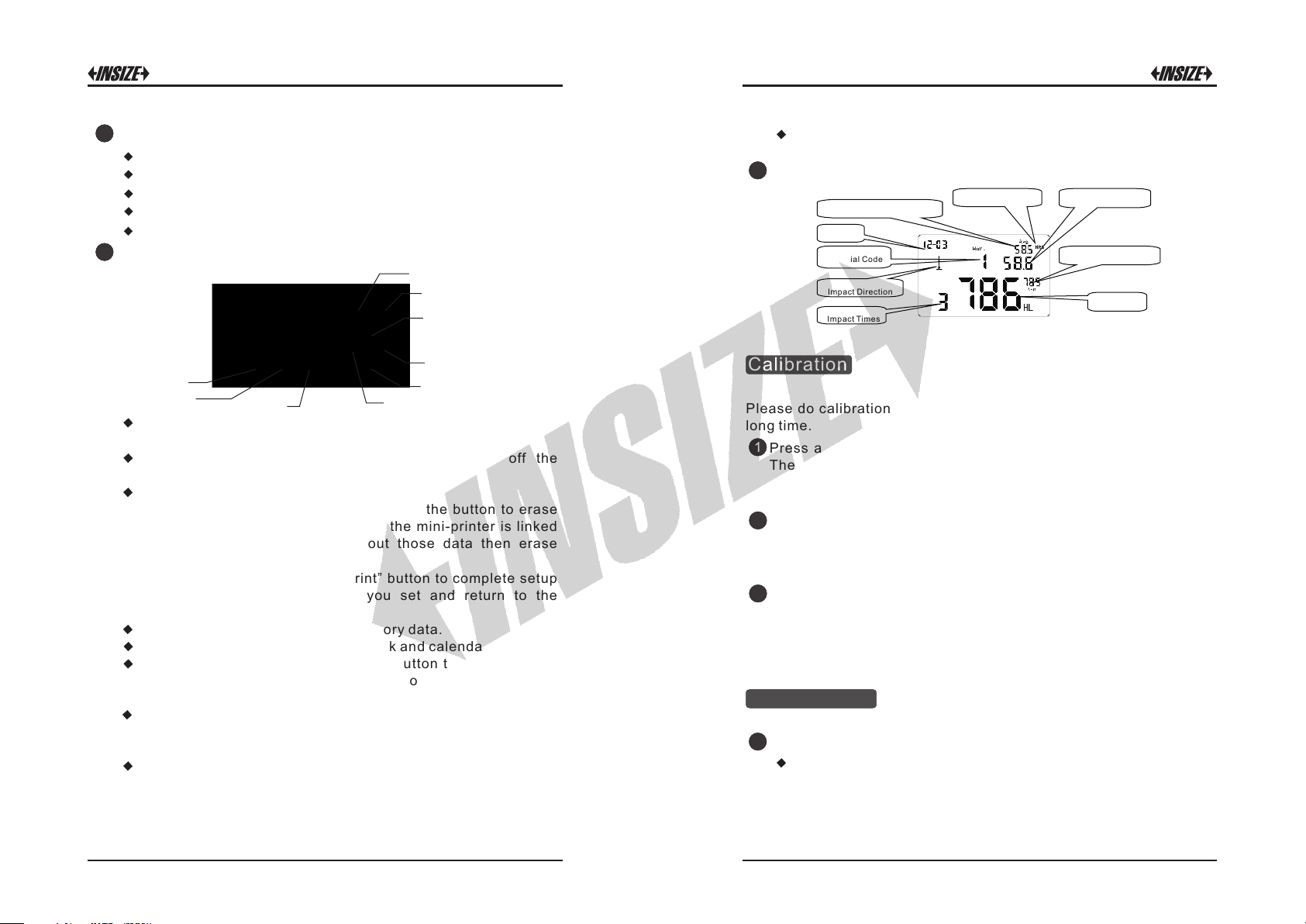
LCD display:
Con versi on Avera ged Va lue
Clo ck
Mat erial C ode
2
1
9
Imp act Dir ectio n
Imp act Tim es
Con versi on Sca le
Con versi on Value
HLD Ave rag ed Valu e
HLD Valu e
8
3
4
1.On /Off but ton: Turn it on /off by pres sing and holding the
butt on.
5
7
6
2. Ba cklight bu tton: Pres s t he bu tton to turn on/off the
back light.
3. “Ba ck/Print” b utton:
① In me asureme nt mode , pre ss an d hol d the bu tton to eras e
meas ured da ta, a t the same ti me, if the m ini-pri nter is li nked
with the mian uni t, it will p rint out those data the n eras e
meas ured data .
②In other mod e, press “Bac k/Print” bu tton to complet e se tup
and sav e the param eters th at you set a nd return to the
meas urement mod e.
4. “Br owse” butto n: Browse t he memory dat a.
5. “Da te/Tim e” button: Adj ust the clo ck and calend ar.
6. “D el.” button: Press and h old t he bu tton to de lete current
data in measurem ent m ode or brows e mode. It a lso u se as the
left d irection bu tton.
7. “Co nvert” butt on: Press t he button to se tup the conve rsion
scal e i n m easurem ent mode. It also use as th e d own direct ion
butt on.
8. “Mat’l” but ton: In m easurem ent mo de, press the button t o
sele ct the materi al that you will im pact. It also us e as the right
dire ction but to n.
Calibration
Plea se do calibra tion when use t he d evice fir st t ime or interv al for a
long t ime.
1
Pres s a nd ho ld the “ Back/Pr int” button to erase measure d dat a.
Then se lect number 01 mater ial and set impact di rection is down .
Meas ure 5 time s on the surfa ce of stan dard block(yo u sh ould
dele te the valu e which devia tion is lar ge).
2
Pres s and h old the “D ate/Time ” butto n about 2 seconds to e nter
the calibrati on interf ace. Use the left an d right d irection buttons t o
move the flic ker. Use the up a nd down directio n button s to ad just
unti l the displ ay value is sam e to the standa rd value of t he block.
3
Pres s “Back/ Prin t” button b ack to the meas urement i nterface.
Note: The distance between any two impact position should be ≥3mm.
the distance between impact position and the edge of the sample
should be ≥3mm.
Measurement
1
Prep aration b efore measu ring:
Sele ct the materi al:
Pres s the “ Mat’l” b utton to select the mat erial co de accor ding
to the b ack label.
3 4
Page 4

Hardness Tensile strength (MPa)
01.Steel and Cast Steel 11. Low Carbon Steel
02. Alloy Tool Steel 12. Hi Carbon Steel
03. Stainless Steel 13. Chrome Steel
04. Grey Cast Iron 14. Cr-V Steel
05. Ductile Iron 15. Cr-Ni Steel
06. Cast Al Alloys 16. Cr-Mo Steel
07. Cu-Zn Alloys 17. Cr-Ni-Mo Steel
08. Cu-Sn Alloys 18. Cr-Mn-Si Steel
09. Copper 19. Hi Strength Steel
10. Forging Steel 20. Stainless Steel
Note: The value can only convert to “Mpa” When select the
material code 11~20.
Impa ct Directio n:
Ideal Leeb Hardness Testing is a downward straight testing
method. As a result of gravity, the test should be amended when
measuring other directions in order to measuring correct
hardness value of material. As long as you correctly choose the
impact direction, ISH-PHA Hardness Tester can automatically be
amended.
On measurement mode, press “Imp. ”button to select the impact
direction.
Convert scale:
ISH-PHA Hardness Tester can automatically convert HLD values
to other hardness scales HRC, HRB, HB, HV, HSD or tensile
strength (MPa) according to a particular material group (e.g.
steel, aluminum etc.)
In measurement mode, press “Convert” button to convert to all
common hardness scales or tensile strength: Press the button
continuously, the scale according to following sequence: HRC→
HRB→HB→HV→HSD→MPa→ HRC…
Note
:
1. The conversion value is “---” indicated the conversion is out of
range.
2. When you set the conversion from hardness scale to tensile
strength or from tensile strength to hardness scale, you must be
reset the material group.
3. Conversion value only supplies the general reference, which
may result in some offset. Precisely conversion generally needs
related comparative tests.
4. When you change the hardness scales, the current impact
time's counter of measuring interface will be clear to “0”.
5. Default setting for the conversion is “HRC”.
Samp le Prepar ation:
Inap propria te sample will cau se a grea t m easuremen t erro r.
Ther efore, users should make the necessar y hand ling and
prep aration u nder the orig inal cond itions of sam ple.
Prep aration of the sa mple and th e s urface of tes t s hould be
coin cident wi th the follow ing basic r equiremen ts:
1) Dur ing the pro cess of sam ple surfa ce pre paratio n, u sers
shou ld avo id the imp acts of cold p ro cessing and the rmal
proc essing.
2) The sample surface is plane for bett er, the test sur face
shou ld be with a m etallic sh een, and not invol ve oxide laye r
orot her stains.
3) Rou ghness of the t est surfa ce Ra ≤ 1.6
4) Sample must be of su ffic ient quality and rigidi ty. If i t's la ck
of q uality an d rigidit y, it may caus e displac ement or shaking i n
the pr ocess of test ing impac t, which can le ad to large e rrors.
Gene rally spe aking, if the s ample qua lity is more th an 5kg can
be di rectly tes ted; if the sample qua lity is 2~5 kgs, the sample
shou ld b e taken in fixa tion test b y means of appr opriate
clam ping; if t he s ample quality i s 0. 1~2kgs, the sam ple
shou ld be c onducted coup ling bef ore th e te st; if the sampl e
qu a l i t y i s l e s s t h an 0. 1 k g , t h i s h a r dn e s s t e s t e r is
inap propria te to use.
Coup ling meth od: Testing sam ple's back should be p repared
to make a pl ane as a sup porting surf ace wit h a s mooth
form ation. Fi lling with a li ttle coup ling substa nce (Indu stry
Vaselin e can b e used), users can no w pres s to th e surf ace of
the sup porting obje ct (The weigh t of sup porting ob ject should
be mor e th an 5 kg, and it ca n be rep laced by test block) to
stic k into integr ation.
5) S amples sh ould be t hick enou gh and wi th sufficie nt surfac e
abso rption layered. If users use D-t ype im pact device, the
thic kness of sa mple should n ot be less th an 5mm, and sur face
abso rption layer (or surfac e-hardeni ng laye r) s hould not b e
less t han 0.8mm. To accurat ely measure t he h ardness o f th e
mate rial, the bes t way is to rem ove the surfa ce-hard ening
5 6
Page 5

mater ial, the be st way is to remo ve the surfac e-hardeni ng
laye r by proces si ng.
6) Wh en testi ng sample s urf ace is not hor izontal, th e
curv ature rad ius of t esting an d nearby surf ace shoul d be
larg er t han 30mm. And approp riate suppo rting ring shou ld b e
elec ted and ins talled.
7) A s ample should not be with magnet ic. The signal of the
impa ct device wou ld be serio usly inter fered in the w or k by the
magn etic, whi ch m ay cause in accurate te st result s.
Meas uring Ste ps:
2
Load ing: S imply load the impact devic e by sliding the loadi ng
tube f orward.
Plac e: Then pla ce and hold the impact device on th e surface
of the test piece at the desir ed test p oint. Impact ind irectio n
shou ld be verti ca l with the te st of surface .
Burs t imp act (Measure ): Trigger the impact by pres sing the
rele ase butt on. The har dness va lue will be insta ntaneousl y
disp layed.
Read o ff t he test resul t from LCD. For e xample:
Samp le materi al: steel and c ast iron;
Impa ct directio n: downwa rds;
Date : 3rd, Dec;
The cu rrent hardn ess value : 786HLD;
The cu rrent measu rement is t he third poin t;
The cu rrent mean va lue: 785H LD
Conv ersions t o HRC: 58.6HR C
The me an value of H RC: 58.5HRC
Repe ating the above steps, users can carry out tests in more
poin ts.
Note : Gene rally, ea ch measu rement l ocation of sam ple is
cond ucted f or th e five tests . The “ S” (diffe rence o f maxim um
valu e and minimum va lue) value s must be less than 15 HL.
The d istance between any two impa ct posit ion shou ld be ≥3
mm ; the d istance b etween impa ct positi on and the ed ge of the
samp le should b e ≥3 mm.
3
Memo ry and prin t:
The data group (suc h as test resul t, conversio n res ult, sample
mate rial an d impac t directi on) aut omatica lly save in memo ry afte r
one individu al mea surement. ISH-PHA hardne ss teste r can s tore
nine sets o f data , when measuring times more t han nine , the last
grou p o f dat a w ill store the 9th posit ion and the first group of data
will be er ased. T he se cond group of da ta wi ll be moved into the
2th pos ition, sim ultaneous ly the posi tion of other group of data,
will b e moved int o lower posit ion.
Pres s and h old “Back /Print” butt on to end th e measure ment an d
prin t out the memo ry data (wh en connect ed to printer ) in test.
Comp leting pr int, the orig inal data w ill be erased a utomati cally.
Back light and a uto-power o ff :
4
High light LED bac klight is used fo r po or lig ht con ditions . Users
can turn on o r turn off the backli ght by press ing th e butt on (it will
auto matical ly save th is mo del whi le sh utdown). If there i s no
meas ure, and no k ey operatio n in 10 secon ds, the backl ight will
7 8
Page 6

be turnin g o ff auto matically, and the displa y u nit w ill be s hut off in
3 minu tes.
Syst em reset :
5
If the displ ay unit is n't w orking properl y or halt, user s can pr ess
the “Reset” b utton by insert a slender r od into t he reset hole at the
back side of di splay u nit, and t hen t he di splay u nit w ill b e
shut down. Press t he button t o reboot the sy stem.
Maintenance
1
Impa ct Device Mai ntenanc e:
Afte r using 10 00-2000 ti mes, us ers s hould c lean the cat heter of
impa ct dev ice and impact body wit h ny lon brush, and scre w off
the sup porting ri ng before clean the cath eter, and th en ta ke out
the imp act body, rotate the nylon br ush in to the tube in an anticloc kwise dir ection, and p ull out whe n touchin g the bot tom. S o
repe atedly, and then load up the impact b ody and supporti ng ring ;
User s sho uld rel ease the i mpact b ody a fter use. And the lubri cant
is ban ned.
Norm al Mainte nance Proce dures:
2
In calib ration of the hardn ess tester, if findi ng t hat error is larger
than 6HLD, u sers m ust be r enew t he s teel b all or i mpact body,
beca use the re ason may be that the s teel ba ll or im pact bo dy is
wore o ut to lead to fai lure in ope ration.
Factors Affection Accuracy
ener gy. Acc ordingl y, the rough ness of s ample testing points o n the
surf ace Ra≤ 1.6.
2) The sha pe of sample su rface
Leeb testi ng princ iple deman ds the velocit y of rebound and impac t
are on t he same lin e, because th e impact bo dy is moving in a metal
tube . Even if the ve locity o f rebound and imp act are n ot on the same
line , it also can s how h ardness fo r sur e, but the impa ct bo dy wo uld
coll ide wi th t ube wa ll w hen it rebou nds, which will affect t he v elocity
of rebou nd. Ther efore, a g reater error is on t est ac curacy. W hen the
radi us of curvatu re of the t esting sampl e sur face is smaller, th e
solu tion is the use of suitable var iant suppo rting ci rcle. If users
requ ire special sup porting circ le, we can contribut e to design and
proc ess.
3) The wei ght of the samp le
If the sa mple weight must be larg er than or equal to 5kg, and not
easi ly sway. If the samp le weight w ere less, the s ample wou ld need
prop er tr eatment (I t is neces sary to in crease the supp orting or
moun ting th rough coupling comp ress on larger weig ht test ing sta nd),
and the test ing result s can be ac hieved in accur acy. There shou ld be
a certain area at the testi ng po ints (the area require d to meet a set of
test ing points) and no vi bration or shak ing. I f th e we ight i s not
enou gh, users mus t be as much as possib le reduce the ji tter and
slos hing by the method s of i ncreasi ng s upporting , couplin g and
comp ressing . And supporti ng device s hould avoid s hock.
4) The sam ple stabili ty
Any effective test s need to mi nimize possibl e inter ference from
outs ide; it's more impor tant to dynamic me asure such as Leeb
hard ness test. T herefore, meas uring only allowe d in stabl e har dness
test ing system. If it's lik ely to l ead to s ample movem ent in t he t ests,
user s should fi x it b efore tes ting.
Inco rrect opera tion o r improper te sting condi tions would hav e
seri ous impact on testing accur acy. Follow ing is several common
fact ors effect the ac curacy of tes ting for th e use of refere nce:
1) Rou ghness of sam ple surfa ce
When the impact body impact on th e samp le, a small pit would arise
on the sample surfa ce, s o a t the same time , sho uld f inish the surface
of the sample. The more r oughnes s, the less cons umption of impact
ener gy wherea s the less roug hness, the mo re consum ption of impa ct
9 10
Page 7

Measuring And Conversion Range
HLD
Materials
Steel & cast steel
Tool steel
Stainless steel
Cast iron
Cast aluminum alloy
Brass
Bronze
Copper
300-900
300-840
300-800
360-650
170-570
200-550
300-700
200-960
HV
HRC HRB
HB
81-654
81-955
80-898
85-655
85-655
85-802
93-334
93-334
19-164
19-164
40-173
60-290
45-315
-68 38 -100
20
20-67
47-101
23
13-95
HS
32 -100 375 -2639
-84
Standard Delivery
Main unit
Impact device D
Printer
Hardness test block
Small support ring
Cleaning brush
AC/DC adapter
1pc
1pc
1pc
1pc
1pc
1pc
1pc
Optional Accessory
Tensile
strength(Mpa)
Support rings
refer to our catalogue
11
 Loading...