


6245
State Road
Philadelphia PA
Telephone
19135-2996
215-624-4800
FAX: 215-624-6966
TECHNICAL MANUAL
including Installation, Operation, and Maintenance Instructions
FOR
DOOR TYPE DISHMACHINES
MODELS
Commander 18-4
Commander 18-4C
Commander 18-4H
CS-4
CS-4C
risd: 1/97
s:\wp51\manual\mn11841
Thank you for Purchasing this quality Insinger product.
On the space provided please record the Model and Serial Number of this unit:
Model: __________________________
Serial Number: ___________________
When referring to this equipment please have these numbers available.
Each piece of equipment at Insinger is carefully tested before shipment for proper operation.
If the need for service should arise please contact your local Authorized Insinger Service
Company. A Service Network Listing is provided within this manual. Check this list for your
local authorized servicer.
For proper activation of the Insinger Limited Warranty a SureFire™ Start-up should be completed
on your machine. Refer to the Introduction section in this manual for an explanation of
Insinger's SureFire™ Start-up and Check-out Program.
Please read the Insinger Limited Warranty and all installation and operation instructions
carefully before attempting to install or operate your new Insinger product.
To register your machine for warranty by phone, fax, or the internet or for answers to
questions concerning installation, operation, or service contact our Technical Services
Department:
Toll-Free 800-344-4802
Fax 215-624-6966
Email service@insingermachine.com
World-Wide Web http://www.insingermachine.com
Thank you.
Insinger Machine Company

6245
State Road
Telephone
DOOR TYPE DISHMACHINES MODEL:
Commander 18-4 & CS Series
Table of Contents
Part 1 - Technical Information
Part 2 - Installation and Operation Instructions
Part 3 - Maintenance and Repair Procedures
Part 4 - Electrical Schematics and Replacement Parts
Part 5 - Replacement Parts
* Section A, Introduction
* Catalogue Cut-sheet and Installation Drawing
* Warranty
* Authorized Service Agency Network Listing
* Section A, Installation Instructions
* Section B, Operation and Cleaning Instructions
* Section A, Maintenance and Repair Procedures
* Basic Service Guide
* Machine Wiring Diagrams
* Control Panel Layout and Component Drawing
* Overall Assembly Drawing for:
* Commander 18-4, 18-4H, CS-4
* Commander 18-4C, CS-4C
* Drain Assembly
* Motor Assembly, 1HP
* Pump, Motor & Suction Assembly
* Level Float Installation
* Electric Heater, Diode and Level float
* Steam Injectors, Steam Coils and Steam Booster Assembly's
* Final Rinse Assembly
* Final Rinse Assembly (self-contained booster)
* Electric Booster Assembly
* Self Contained Booster Assembly
* Gas-heated Machines
* Parts Listing
* Troubleshooting
* Sequence of Operations
Philadelphia PA
19135-2996
215-624- 4800
FAX: 215-624-6966

COMMANDER 18-4 Series & CS Series
intended for the daily users of the equipment. The maintenance and parts sections are intended for qualified service and/or
When calling for warranty information or replacement parts please provide the model and
be noted in this manual on the spaces provided
out Program to our commercial customers. This service
is included in the purchase price of your new Insinger dishwasher. We will provide an authorized factory service technician
TECH MANUAL INTRODUCTION
Part 1, Section A
A.
INTRODUCTION
A.1
Purpose The purpose of this Tech Manual is to provide installation, operation, cleaning and maintenance directions.
A section is provided for replacement parts.
A.2
Scope
This manual contains all pertinent information to assist in the proper installation, operation, cleaning, maintenance, and
parts ordering for the Commander 18-4 series and CS-4 series dishwashers.
The installation instructions are intended for qualified equipment installers. The operation and cleaning instructions are
maintenance technicians.
Replacement parts may be ordered directly from our factory or from your local Insinger Authorized Service Agency. For the
name of your local Insinger Authorized Service Agency please reference the Service Network Listing in Section 1 of this
manual. You can also speak to the Insinger Technical Services Department, 800/344-4802, or e-mail us at
service@insingermachine.com.
serial number of your Insinger equipment. These important numbers should
on the opening page.
A.3
Start-Up Program
Insinger is proud to offer our exclusive Surefire™ Start-up & Check-
for the initial start-up of your new Insinger dishwasher to ensure it is running correctly. Please call the factory or your local
Insinger Sales Representative to schedule this service.
A.4
Definitions
Throughout this guide you will find the following terms: WARNI NG, CAUTION, & NOTE. When used, these terms will be
outlined in a box to draw attention:
WARNING: indicates potential physical danger.
CAUTION: indicates potential equipment damage.
NOTE: indicates helpful operating hints or tips.

CS-4
NOTES:
AUTOMATIC SINGLE TANK
CHEMICAL SANITIZING DOOR
TYPE DISHWASHER
DESIGN
Automatic door type, single tank dishwasher with a timed wash-and-rinse cycle. Fully
automatic operation with power on/off button. Capacity is 80 racks per hour for light soil
(60 racks per hour for normal soil) - 20" x 20" racks. Cycle starts when doors are closed.
Designed for straight through operation. Corner model available for right angle operation.
STANDARD EQUIPMENT
• Tank heat: 3 KW electric immersion • Space Saving Compact Design
heater or steam injector • Fully Automatic Operation
• NSF approved Sanitizer Injector Pump • Top Mounted Control Panel
• Capillary Thermometer for Wash (NEMA12)
• In-Line Thermometer for Final Rinse • Simplified Scrap Screen Design
• Vacuum Breaker • Door Safety Switch
• Four Plastic 20" x 20" Racks (2 Plate • Interchangeable Upper & Lower Spray
Racks and 2 Silver Racks) Arms
• Manifold Cleanout Brush • Standard Frame Drip Proof Motor
• Inspection Door • Override Switch for De-liming
• S/S frame with S/S Legs
• Automatic Tank Fill
• Low Water Protection
• Detergent Connection Provision
OPTIONAL ACCESSORY EQUIPMENT
• Pressure Reduction Valve and Line
Strainer
• Stainless steel steam coil tank heat Gas
tank heat
• Security package
• Totally Enclosed Motors
• Door Activated Drain Closer
6245 State Road
Philadelphia PA 19135-2996
215/624-4800
215/624-6966 FAX
800/344-4802

Final rinse
Exhaust hood
Peak rate
Shipping
Current draw Steam/Gas Electric
460/3/60..........................................2................................6
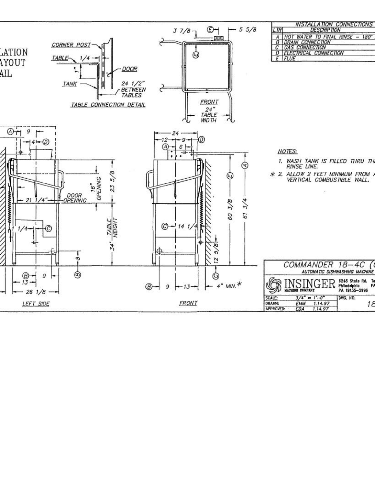
Note: For all rough in connections see Installation and Layout Detail Drawing.
SPECIFICATIONS
CONSTRUCTION—Hood and tank constructed of 16 gauge 18-8 type 304 S/S. Hood unit of all welded seamless
construction. S/S base frame and legs. All internal castings are non-corrosive lead free nickel alloy or bronze.
DOORS—a front inspection/cleanout door and two simultaneously opening operating doors. Operating doors have
fingertip control, balanced by externally mounted springs. (Corner model available with 2 doors at right angles.) Extra
large die formed 18-8 type 304 S/S doors ride in all S/S channels. A triple ply leading edge on the door channels made
of S/S with no plastic or nylon sleeves or liners used.
PUMP— Centrifugal type "packless" pump with a brass petcock drain. Construction includes ceramic seal and a
balanced cast impeller on a precision ground stainless steel shaft. All working parts mounted as an assembly and
removable as a unit without disturbing pump housing. One 1 HP motor, standard frame, horizontal C-faced, drip
proof, squirrel-cage, induction run type, 60 cycle, 3400 RPM, internally cooled with ball-bearing construction.
CONTROLS— Top-mounted control cabinet, NEMA 12 rated with heat insulation provided between hood and control
cabinet, housing motor controls and overload protection, transformer, contactors and all dishwasher integral controls.
All controls safe low voltage 24 VAC.
SPRAY SYSTEM —Wash and rinse spray systems made of 18-8 type 304 S/S schedule 40 pipe threaded into cast
hub assemblies. Upper and lower spray assemblies are interchangeable and are removable without the use of tools.
Wash—2 power spinning wash arms above and 2 power spinning wash arms below each designed with 4 high
pressure action cleansing slots. The slots are precision milled for water control producing a fan spray.
Final Rinse—2 power spinning rinse arms above and 2 power spinning rinse arms below each designed with 4 nozzle
assemblies.
Nozzle assemblies produce a cone spray reducing water consumption, maximizing heat retention. The final rinse
piping is Chlorinated Poly Vinyl Chloride.
DRAIN—Drain valve externally controlled. Overflow assembly with skimmer cap is removable without use of tools for
drain line inspection. Heater protected by low water level control.
Capacity Tank capacity Motor size Electric usage Steam consump- Final rinse peak
per hour
60 racks
1500 dishes 5.6 gals. 1 hp 3 kw wash tank 11 lbs./hr.tank 1.1 gals./min.
75-150 meals
tion at 20 psi min. flow at 20 psi min.
at 20 psi min.
68 gals./hr. 100CFM 9 gals./min. 550 Ibs.
1.13gals./rack
115/1/60.........................................11..............................43
208/3/60..........................................5...............................13
230/1/60..........................................7...............................19
230/3/60..........................................4...............................11
380/3/60..........................................3................................9

Commander 18-3
£
Pressure Reduction Valve and
£
Built-in electric booster
£
Remote electric booster
£
Stainless steel steam coil tank heat
£ Security package
£ Gas t
ank heat
£ Totally Enclosed Motor
£ Steam booster
£ Door Activated Drain Closer
AUTOMATIC SINGLE TANK
DOOR TYPE DISHWASHER
DESIGN
Automatic door type, single tank dishwasher with timed wash-and-rinse cycle. Fully
automatic operation with power on/off button. Capacity is 65 - 20" x 20" racks per hour, or
1625 dishes per hour. Cycle starts when doors are closed. Designed for straight through
operation. Corner model available for right angle operation.
STANDARD EQUIPMENT
• Space saving compact design • Capillary Thermometer for Wash
• Door Safety Switch • In-Line Thermometer for Final Rinse
• Detergent Connection Provision • Vacuum Breaker
• Fully Automatic Operation • Four Plastic 20" x 20" Racks
• Top Mounted Control Panel (2 Plate Racks and 2 Silver Racks)
(NEMA12) • Manifold Cleanout Brush
• Simplified Scrap Screen Design • Inspection Door
• Interchangable Upper and • S/S frame with S/S Legs
Lower Wash and Rinse Arms • Automatic Tank Fill
• Standard Frame Drip Proof Motor • Low Water Protection
• Tank heat: 3 KW electric immersion • Override Switch for De-liming
heater or steam injector
OPTIONAL ACCESSORY EQUIPMENT
Line Strainer
NOTES:

65
racks
1625
dishes
13.5
kw b.i. booster
40°rise
6
kw rem. booster
Current draw Steam/Gas Electric Electric
amps w/o Booster w/ Built
-
in Booste
r
consumption
requirement
drain flow
weight
115/1/60.......................11.
.....................43........…........
n/a
at
20
psi min.
208/3/60.......................5........................13........…........51
230/1/60................
.......7........................19........…........81
230/3/60.......................4........................11
........…........51
380/3/60.......................3...................
.....9..........….......n/a
460/3/60.......................2........................6.........….........24
Note: For all rough in connections see Installation and Layout Detail Drawing.
SPECIFICATIONS
CONSTRUCTION—Hood and tank constructed of 16 gauge 18-8 type 304 S/S. Hood unit of all welded seamless
construction. S/S base frame and legs. All int ernal castings are non-corrosive lead free nickel alloy or bronze.
DOORS—a front inspection/cleanout door and two simultaneously opening operating doors. Operating doors have
fingertip control, balanced by externally mounted springs. (Corner model available with 2 doors at right angles.) Extra
large die formed 18-8 type 304 S/S doors ride in all S/S channels. A triple ply leading edge on the door channels
made of S/S with no plastic or nylon sleeves or liners used.
PUMP—Centrifugal type "packless" pump with a brass petcock drain. Construction includes ceramic seal and a
balanced cast impeller on a precision ground stainless steel shaft. Alt working parts mounted as an assembly and
removable as a unit without disturbing pump housing. One 1 HP motor, standard frame, horizontal C-faced, drip proof,
squirrel-cage, induction run type, 60 cycle, 3400 RPM, internally cooled with ball-bearing construction.
CONTROLS—Top-mounted control cabinet, NEMA 12 rated with heat insulation provided between hood and control
cabinet, housing motor controls and overload protection, transformer, contactors and all dishwasher integral controls.
All controls safe low voltage 24 VAC.
SPRAY SYSTEM —Wash and rinse spray systems made of 18-8 type 304 S/S schedule 40 pipe beaded into cast hub
assemblies. Upper and lower spray assemblies are interchangeable and are removable without the use of tools.
Wash—2 power spinning wash arms above and 2 power spinning wash arms below each designed with 4 high pressure
action cleansing slots. The slots are precision milled for water control producing a fan spray.
Final Rinse—2 power spinning rinse arms above and 2 power spinning rinse arms below each designed with 4 nozzle
assemblies.
Nozzle assemblies produce a cone spray reducing water consumption, maximizing heat retention.
DRAIN—Drain valve externally controlled. Overflow assembly with skimmer cap is removable without use of tools for
drain line inspection. Heater protected by low water level control.
Capacity Tank capacity Motor size Electric usage Steam consumption Final rinse peak
per hour
75-150 meals
Final rinse Exhaust hood Peak rate Shipping
5.6 gals. 1 hp(wash)
3 kw wash tank
l0kw rem. booster 70°rise 21 lbs./hr. booster 40°rise
at 20 psi min. flow at 20 psi min.
11 Ibs./hr.tank 2.56 gals./min.
58.5 gals./hr.
.90 gals./rack
100CFM 9 gals./min. 550 Ibs.


COMMANDER 18-4 Series & CS Series
INSTALLATION INSTRUCTIONS
Part 2, Section A
A.1 PLACEMENT
A.1.1 Carefully uncrate machine. Take caution to not damage components which may be mounted on the top or
sides of the machine.
A.1.2 Set unit in place and adjust the feet to level the machine.
A.1.3 Fasten the tables to the load and unload side of the
machine. Most installations require fastening the turn -down lip of the dish tables to the side of the machine with
flathead counter-sunk screws. The table design should provide horizontal clearance of 30" for servicing.
A.2 ELECTRICAL CONNECTIONS
A.2.1 Connect electrical lines sized for the correct voltage,
current and phase of the machine. These should agree with machine requirements indicated on the nameplate
and labels in control panel.
A.2.2 A single-point electrical connection is provided for the pumps, control circuit, and wash tank heater.
A.2.3 If an electric water booster is provided connect the power directly to the booster. If the Insinger Self -Contained
booster is provided the machine comes standard with a Single-Point Connection (to include the booster).
Caution
Fuse Sizing Chart
Model
18-4(C)
steam heat
18-4(C)
electric heat
18-4(C)
electric heat
Insinger SCB
18-4H
steam heat
18-4H
electric heat
Connections must be made to a circuit breaker or fused disconnect as provided by the
end-user and required by local codes. A laminated wiring diagram is inside the control
panel.
208VAC/3Θ 230VAC/3Θ 380VAC/3Θ 460VAC/3Θ 220VAC/1Θ
6A 6A 6A 6A 15A
15A 15A 10A 10A 25A
60A 45A 30A 25A 90A
10A 10A 6A 6A 20A
25A 25A 15A 15A 40A

COMMANDER 18-4 Series & CS Series
INSTALLATION INSTRUCTIONS
Part 2, Section A
Caution
As with any 3 phase system, an electrician must check all motors for proper
phasing, i.e.. Pump motors must be running in direction indicated by arrow on
housing.
A.3 MECHANICAL CONNECTIONS
A.3.1 Connect 140DEGF water lines for tank fill/booster as tagged and noted on the
installation drawings.
A.3.2 If machine is provided with steam heat connect the steam lines and steam condensate
lines as tagged and noted on installation drawings.
If machine is provided with gas heat, connect the gas lines
A.3.3 Connect the drain line.
for each tank.
Caution
Drain lines must be as specified on installation drawings.
Drain line should be properly vented and should have fall of
not less than 1/4 to the foot of proper flow. Some area
plumbing codes require drains to flow into an open gap with
an opening twice the diameter of the pipe. Check with your
local plumbing codes for the type of drain connection
required.
Caution
All lines must be flushed prior to use to remove
debris.
Caution
Do not reduce the size of lines as specified in installation
drawings. All lines are sized to facilitate necessary flows,
pressures, etc.
A.4 HVAC
A.4.1 Ventilation syst em must be sized to provide adequate ventilation per machine specs. Refer to spec
sheet.

COMMANDER 18-4 Series & CS Series
INSTALLATION INSTRUCTIONS
Part 2, Section A
A.5 Chemicals
A.5.1 Upon completed installation of the dishwasher contact a
local detergent/chemical supplier for the correct chemicals for your area.
A.5.2 Electrical connection points for the detergent dispenser and rinse injector are located inside the control panel.
Refer to the wiring diagram for this machine for the proper connection points. Dispensers may be connected on
either the primary voltage side of the machine or the 24VAC control voltage side.
Caution
When connecting on the 24VAC control voltage side of the transformer, total VA
must not exceed 5OVA.
A.5.3 The detergent density probe should be installed in the hole provided & labelled in the wash tank.
A.5.4 A switch on the control panel labelled "Wash Cycle" is provided for de-liming the machine. When
activated, this switch will keep the machine in an indefinite wash cycle. This feature can also be used to
wash heavily soiled ware on an ex tended wash cycle.
A.6 Tabling
A.6.1 Load and unload tables should be pitched towards the machine to return excess water into the machine.

DOOR TYPE DISHMACHINES
MAINTENANCE and REPAIR PROCEDURES
Part 3, Section A
Following is a basic guide for the repair and replacement of common
dishwasher parts.
Refer to the Basic Service Guide for troubleshooting tips.
A.1 MAINTENANCE
A.1.1 Daily - Refer to the operation and cleaning instructions
provided in this manual for daily cleaning procedures.
A.1.2 Weekly
A.1.2.1 The entire machine should be wiped down using an
industrial grade stainless steel cleaner.
A.1.2.2 Under the supervision of your detergent supplier the machine interior must be properly de-limed.
Note
The water quality in some areas requires de-liming to be done
more frequently. Contact your detergent supplier for
recommended de-liming frequency.
A.1.3 Quarterly
A.1.3.1 Remove and clean the strainer screens on water and
steam lines. If the screens cannot be cleaned, replace.
A.1.3.2 Inspect condition of solenoid valve seats and diaphragms.
Replace where necessary.
A.1.3.3 Inspect drain O-Rings for leakage. Replace where necessary.
A.1.3.4 Check door spring tension and adjust where necessary.
A.1.3.5 Check wash and rinse hub bushing/bearing and replace where
necessary.
A.2 MAINTENANCE PROCEDURES
A.2.1 Solenoid Valve Disassembly
A.2.1.1 Disconnect power supply to machine. Turn off Water supply.
A.2.1.2 Remove cap on top of coil. Remove coil.
A.2.1.3 Remove 4 hex bolts and lift bonnet from valve body. Note positioning
of spring and plunger
A.2.1.4 Remove main piston.
A.2.1.5 Inspect for dirt, wear or lime build-up. Clean or replace as required.
A.2.1.6 Reassemble in reverse of disassembly.

DOOR TYPE DISHMACHINES
MAINTENANCE and REPAIR PROCEDURES
Part 3, Section A
A.2.2 Line Strainer Disassembly
A.2.2.1 Shut off water or steam supply.
A.2.2.2 Remove large hex nut on bottom of strainer body.
A.2.2.3 Remove strainer sc reen. Inspect and clean or replace as necessary.
A.2.2.4 Reassemble in reverse of disassembly. Water flow must be same direction
as arrow on line strainer body. Use new gaskets to insure a tight seal.
A.2.3 Pump Disassembly
A.2.3.1 Before disassembling pump ensure there are no obstructions in the pump intake.
Remove and clean the suction strainer(inside tank).
A.2.3.2 IT IS NOT NECESSARY TO REMOVE THE PUMP HOUSING FROM THE
MACHINE TO DISASSEMBLE THE PUMP.
A.2.3.3 Remove the pump motor and impeller adaptor by removing the 4 hex bolts
attaching them to the pump housing.
A.2.3.4 Repair or replace the pump parts as required.
A.2.3.5 Reassemble in reverse of disassembly.
A.2.4 Immersion Heater Replacement
A.2.4.1 The immersion heater MUST be completely submerged at all times. If this
is not the case contact a qualified service technician. The heated surface
should never be in contact with sludge.
A.2.4.2 Remove the housing covering the wiring terminations. Disconnect the
immersion heater wires.
A.2.4.3 Remove the immersion heater by loosening and remov ing the large
hex nut .
A.2.4.4 Install in reverse of removal.
Note
To reduce the possiblity of leaking, use plumbers putty on the immersion heater
nuts.
A. 2. 5 Wash Tank Temperature Adjustment
A.2.5.1 A temperature control board is provided in the control panel for easy adjustment of tank temperature.
A.2.5.2 Locate the temperature control board (P/N DE9-96). Use the control panel layout drawing located in
Though tank temperature is adjusted during the machines factory test it is sometimes necessary to readjust the temperature at start -up.
Section 3, Electrical Schematic and Replacement Parts.

DOOR TYPE DISHMACHINES
MAINTENANCE and REPAIR PROCEDURES
Part 3, Section A
A.2.5 Wash Tank Temperature Adjustment cont'd
A.2.5.3 Adjust the tank temperature to the desired
temperature by turning the potentiometer located on the temperature control board. An arrow on the
potentiometer indicates increase.
A.2.5.4 If the temperature does not change refer to
section A.2.6, Troubleshooting Tank Temperatures.
A.2.6 Troubleshooting Tank Temperatures
A.2.6.1 Electric Heat
A.2.6.1.1 If temperature cannot be adjusted per section A.2.5 check the temperature
control board P/N DE9-96 proper operation. If the temperature control board is faulty, replace.
A.2.6.1.2 Verify tank heat contactor is working correctly. If not, replace.
A.2.6.1.3 Verify all immersion heaters are working properly and not limed. If not, replace
A.2.6.2 Steam Heat
A.2.6.2.1 See Section A.2.6.1.1.
A.2.6.2.2 Verify steam pressure per machine specifications.
A.2.6.2.3 Verify steam trap is not clogged. IF so, replace.
A.2.6.3 Gas Heat
A.2.6.3.1 See Section A.2.6.1.1.
A.2.6.3.2 Verify gas supply.
A.2.6.3.3 Verify pilot is lit. If not, light. If pilot does not stay lit, replace.
A.2.6.3.4 Verify gas solenoid is working correctly. If not, replace.
A.2.7 Motor Overloads
A.2.7.1 All motors used on Insinger Machines are provided with motor overloads. Motor overloads are adjusted
when the machines are factory tested. Should it be necessary to adjust the motor overloads in the field
first verify the motor current draw for the voltage the machine is using.
A.2.7.2 Using the Control Panel Component Layout Dwg. located in Section 3 to identify the overload adjust by
turning the dial to the appropriate AMP draw.

DOOR TYPE DISHMACHINES
MAINTENANCE and REPAIR PROCEDURES
Part 3, Section A
A.2.8 Level System
A.2.8.1 The level control system consists of one timer(P/N DE7-31) and two
level floats (P/N DE5-60) per tank.
A.2.8.2 The level timer will not allow the tank heat to energize without water in
the tank.
A.2.8.3 Should the tank heat energize with out water in the tank troubleshoot the system
to find the problem.
Caution
Dirty level floats may cause the tank heat to energize with no water in the tanks.
LEVEL FLOATS MOST BE CLEANED DAILY.
A.2.9 Wash and Rinse Cycle
A.2.9.1 The timing sequence consists of two timers. The Commander 18-3 and CS-4 use two, one minute timers
(P/N DE7-27) . The CA -3 and DA-3 use one, one minute timer (P/N DE7-27) and one, five minute timer
(P/N DE7-28) . Should either of these become defective, replace.

BASIC SERVICE GUIDE
SYMPTOM
POSSIBLE CAUSE
Solution
1.
Machine will not
a.
No Power
a.
Check power
2. Tank will not
a. Drain not closed
a. Close drain
3.
Tank fills
a. Obstruction in
a.
Remove
4.
Water leaks
a. Doors not
a.
Reseat doors
5.
Weak or
a. Clogged spray
a. Clean spray
operate b. Blown fuse or supply
tripped breaker b. Replace fuse;
c. Motor overloads reset breaker
tripped c. Reset overload
hold water b. Drain overflow b. Reseat or
not seated or install drain
installed overflow
c. Pump petcock c. Replace V -seal
opened
beyond overflow overflow tube or obstruction
drain line
around door seating b. Clean spray
b. Clogged spray pipe with
pipe brush provided
ineffective spray pipe pipe with
brush pipe
b. Manifolds not b. Ensure proper
installed placement of
properly upper and
lower pipes
c. Obstruction in c. Clear
pump obstruction
through pump
inspection
plate
d. Pump rotation d. Arrow on pump
reversed housing
indicates
direction,
correct
electrically
e. Suction strainer e. Clean suction
clogged strainer

BASIC SERVICE GUIDE
SYMPTOM POSSIBLE CAUSE Solution
6. Weak or ineffective final rinse spray a. Lime deposits in spray nozzles a. Clean or replace nozzles
b. Low water pressure b. Adjust to 20PSI
c. Clogged line strainer c. Remove line strainer and clean
d. Closed water supply valve d. Open ball valve
7. Water hammer a. Excessive water line pressure
8. Machine vibrates or is noisy a. Pump rotation reversed
b. Pump bearings worn b. Replace pump bearings
9. Final rinse will not shut off a. Final rinse solenoid valve clogged
b. Diaphragm worn
c. Solenoid valve still powered-up
a. Install water hammer limiting
device
a. Arrow on pump housing
indicates direction, correct
electrically
a. Disassemble valve and clean
internal parts of scale or replace
b. Replace with solenoid valve
repair kit
c. Check final rinse actuating
circuit for proper operation

BASIC SERVICE GUIDE
SYMPTOM POSSIBLE CAUSE Solution
10. Tank not filling/tank heat coming on
with no water in tank
a. Level float dirty
b. Level control system not working b. Troubleshoot level control circuit
11. Tank temperature too low/high a. Thermostat not adjusted
b. Heat circuitry not working b. Troubleshoot circuitry
c. Electric heat, power turned off c. Turn power on
d. Electric heat, immersion heaters
limed
e. Steam heat, steam turned off e. Turn steam on
f. Steam heat, not enough steam
g. Steam heat, condensate traps
clogged
h. Gas heat, gas turned off h. Turn on gas
i. Gas heat, pilot not lit i. Re-light pilot
a. Clean level float with Scotch-
Brite or equivalent - two floats
per tank
a. Adjust thermostat located in
control panel
d. De-lime machine
f. Adjust steam pressure per
machine spec's
g. Clean or replace condensate
traps


PART 5
REPLACEMENT PARTS

PARTS LIST: COMMANDER 18-4 & 18-4H
ITEM MACHINE PART No. DESCRIPTION REQ.
1 18-4 18-4H 1089-19 PUMP & MOTOR ASS'Y (1 H.P. - SPECIFY VOLTAGE) 1
2
3
4
5
6
7
8
9
10
11
12
13
14
15
16
17
18
19
20
21
22
23
24
25
26
27
28
29
30
31 18-4 1089-8 DOOR - SIDE 2
32 18-4 1084-25 DOOR ARM 1
33 18-4 1084-38 LINK, ARM-DOOR 2
34 18-4 957-26 SPACER. S/S. DOOR - ARM LINK 2
35
36
37 18-4 957-27 SPRING EXTENSION - LOWER 2
38
39
40
41 18-4 1089-57 DOOR - FRONT 1
42
43
44
45
46
47
48
1463-16 DISCHARGE LINE ASS'Y 1
D-2483A "Y” STRAINER, 1/2 1
1084-76 SPRAY HUB - WASH 2
D2-563 O-RING 2
952-27 BUSHING, PLASTIC (WASH ARM HUB) 2
1089-178 BUSHING. PLASTIC (RINSE ARM HUB) 2
1089-23 WASH SPRAY PIPES 4
D2-554-2 PLUG, 3/4-10 UNC-2A (WASH ARM) 4
D2-584 LOCKING SCREW 2
372-52 HUB - RINSE ARM 2
1084-35 BUSHING. BRONZE (RINSE ARM HUB) 2
1463-21 LOWER RINSE ARM ASS'Y 1
1463-20 UPPER RINSE ARM ASS'Y 1
D-2700 SPRAY NOZZLE - UPPER RINSE ARM 4
D-2836 SPRAY NOZZLE - LOWER RINSE ARM 4
D-2497 PETCOCK 1
D2-554-1 PLUG. 9/16-12 UNC-2A 4
D-2241A VACUUM BREAKER, 1/2 1
D-2242A VACUUM BREAKER REPAIR KIT 1
1463-18 FINAL RINSE ASSEMBLY 1
SK-3028 DRAIN ASSEMBLY ( W/PARTS LIST) 1
D-2606 SOLENOID VALVE. 1/2 1
D-2641 SOLENOID VALVE REPAIR KIT 1
D-2495 TEMPERATURE GAUGE - FINAL RINSE 1
D-2390 TEMPERATURE GAUGE 1
1084-14A TRACK ASS'Y 2
1089-9 TRAY SUPPORT 2
1089-10 SCRAP SCREEN 1
D-2430 BULLET FOOT 4
D-2245 GRIP - DOOR HANDLE 2
SK-2294A SPRING 2
1089-12 SPRING BRACKET 1
DE5-37 SWITCH, MAGNETIC 1
DE5-37A MAGNET 1
D-2099 HANDLE, FRONT DOOR 1
1089-59 FRONT DOOR HANGER 1
SK-3490 CONTROL BOX ASS'Y 1
1089-16A MANIFOLD ASS'Y, LOWER 1
1089-15A MANIFOLD ASS'Y. UPPER 1
D-1003 PRESSURE GAUGE 1
DE5-60 LIQUID LEVEL FLOAT 2

PARTS LIST: COMMANDER CS
-4
ITEM MACHINE PART No. DESCRIPTION REQ.
1
2
3
4
5
6
7
8
9
10
11
12
13
14
15
16
17
18
19
20
21
22
23
24
25
26
27
28
29
30
31
32
33
34
35
36
37
38
39
40
41
42
43
44
45
46
47
48
18-4
18-4
18-4
18-4
18-4
18-4
18-4
1089-19
1463-16 DISCHARGE LINE ASS'Y 1
D-2483A "V” STRAINER . 1/2 1
1084-76 SPRAY HUB - WASH 2
D2-563 O-RING 2
952-27 BUSHING. PLASTIC (WASH ARM HUB) 2
1089-178 BUSHING. PLASTIC (RINSE ARM HUB) 2
1089-23 WASH SPRAY PIPES 4
D2-554-2 PLUG. 3/4-10 UNC-2A (WASH ARM) 4
D2-584 LOCKING SCREW 2
372-52 HUB - RINSE ARM 2
1084-35 BUSHING. BRONZE (RINSE ARM HUB) 2
1463-21 LOWER RINSE ARM ASS'Y 1
1463-20 UPPER RINSE ARM ASS'Y 1
D-2700 SPRAY NOZZLE - UPPER RINSE ARM 4
D-2836 SPRAY NOZZLE - LOWER RINSE ARM 4
D-2497 PETCOCK 1
D2-554-1 PLUG. 9/16-12 UNC-2A 4
D-2241A VACUUM BREAKER, 1/2 7
D-2242A VACUUM BREAKER REPAIR KIT 1
1463-18 FINAL RINSE ASSEMBLY 1
SK-3028 DRAIN ASSEMBLY ( W/PARTS LIST) 1
D-2606 SOLENOID VALVE. 1/2 7
D-2641 SOLENOID VALVE REPAIR KIT 7
D-2495 TEMPERATURE GAUGE - FINAL RINSE 7
D-2390 TEMPERATURE GAUGE 7
1084-14A TRACK ASS'Y 2
1089-9 TRAY SUPPORT 2
1089-10 SCRAP SCREEN 7
D-2430 BULLET FOOT 4
1089-8
1084-25
1084-38
957-26
D-2245 GRIP - DOOR HANDLE 2
SK-2294A SPRING 2
957-27
1089-12 SPRING BRACKET 1
DE5-37 SWITCH. MAGNETIC 1
DE5-37A MAGNET 1
1089-57
D-2099 HANDLE. FRONT DOOR 1
1089-59 FRONT DOOR HANGER 1
SK-3490 CONTROL BOX ASS'Y 1
1089-16A MANIFOLD ASS'Y, LOWER 1
1089-15A MANIFOLD ASS'Y. UPPER 1
D-1003 PRESSURE GAUGE 1
DE5-60 LIQUID LEVEL FLOAT 2
PUMP & MOTOR ASS'Y (1 H.P. - SPECIFY VOLTAGE)
DOOR - SIDE 2
DOOR ARM 1
LINK. ARM-DOOR 2
SPACER, S/S. DOOR - ARM LINK 2
SPRING EXTENSION - LOWER 2
DOOR - FRONT 1
1


PARTS LIST
-
COMMANDER 18
-4C
ITEM PART NO. DESCRIPTION REQ.
2
1 D-2465 PUMP & MOTOR ASS'Y (1 H.P. - SPECIFY VOLTAGE) 1
2 D2-541 SUCTION STRAINER 1
2A D3-825 SUCTION STRAINER SPRING 1
3 1463-16 DISCHARGE LINE ASS'Y 1
4 D-2483A ''V" STRAINER. 1/2 1
5 1084-76 SPRAY HUB - WASH 2
6 D2-563 O-RING 2
7 952-27 BUSHING 2
8 1089-178 BUSHING. PLASTIC 2
9 1089-23 Rev.A WASH SPRAY PIPES (UPPER & LOWER) 4
10 D2-554-2 PLUG. 3/4-10 UNC-2A 4
11 D2-584 LOCKING SCREW 2
12 1084-22 SPRAY HUB - RINSE 2
13 1084-35 BUSHING - UPPER 2
14 1084-36 BUSHING - LOWER
15 1463-21 RINSE. LOWER SPRAY PIPE ASS'Y 1 SET
15A 1463-20 RINSE, UPPER SPRAY PIPE ASS'Y
16 D2836 RINSE SPRAY NOZZLES - LOWER PIPE RINSE 4
16 A D2700 RINSE SPRAY NOZZLES - UPPER PIPE RINSE 4
17 D-2497 PETCOCK 1
18 D2-554-1 PLUG, 9/16-12 UNC-2A 4
19 D-2241 A VACUUM BREAKER. 1/2 1
19 A D-2242A VACUUM BREAKER REPAIR KIT 1
21 1169-179 DRAIN ASS'Y 1
22 1100-79 A DRAIN HANDLE ASS'Y 1
23 D-2606 SOLENOID VALVE. 1/2 1
23A D-2641 SOLENOID VALVE REPAIR KIT 1
24 D-2495 TEMPERATURE GAUGE - FINAL RINSE 1
25 D-2390 TEMPERATURE GAUGE 1
26 1089-107 TRACK ASS'Y 2
29 1089-9 TRAY SUPPORT 2
30 1089-10 SCRAP SCREEN 1
31 D-2430 BULLET FOOT 4
32 1089-8 DOOR - SIDE 2
33 1084-126 DOOR ARM 1
34 1084-119 LINK - DOOR ARM 2
35 957-26 SPACER - DOOR ARM LINK 2
36 952-118 PIVOT BRACKET - DOOR ARM 2
37 D2-551 PIVOT BALL 1
38 952-139 SUPPORT - PIVOT BRACKET 2
39 SK-2294A SPRING 2
40 957-27 SPRING EXTENSION - LOWER 2
41 1089-118 SPRING BRACKET 1
42 DE5-37 SWITCH. MAGNETIC 1
43 DE5-37A MAGNET 1
44 957-49 SPRING EXTENSION - UPPER 2
45 1089-108 CORNER TRACK 1
46 SK-3490 CONTROL BOX ASS'Y 1
47 DE5-60 LIQUID LEVEL FLOAT 1
48 1089-16A MANIFOLD ASS'Y, LOWER 1
49 1089-15A MANIFOLD ASS'Y, UPPER 1
50 D-1003 PRESSURE GAUGE 1
52 963-38 SUCTION STRAINER FLANGE 1
53 D514 GASKET. PUMP FLANGE 1
54 D134 PUMP FLANGE 1
55 D316A-H3-H4 1 7/2" 90' ELBOW 1
56 D207A-12-12.5 1 1/2" TUB. Cu, 3 1/8" Lg. 1
57 D317A-H3-H2 ADAPTER 11/2" 1
58 D314F -HT-72 NIPPLE 1 1/2" IPS x 9" Lg. LOE 1

PARTS LIST: CS-4C
2
ITEM PART NO. DESCRIPTION REQ.
1 D-2465 PUMP & MOTOR ASS'Y (1 H.P. - SPECIFY VOLTAGE) 1
2 D2-541 SUCTION STRAINER 1
2A D3-825 SUCTION STRAINER SPRING 1
3 1463-16 DISCHARGE LINE ASS'Y 1
4 D-2483A "Y" STRAINER, 1/2 1
5 1084-76 SPRAY HUB - WASH 2
6 D2-563 O-RING 2
7 952-27 BUSHING 2
8 1089-178 BUSHING, PLASTIC 2
9 1089-23 Rev.A WASH SPRAY PIPES (UPPER & LOWER) 4
10 D2-554-2 PLUG. 3/4-10 UNC-2A 4
11 D2-584 LOCKING SCREW 2
12 1084-22 SPRAY HUB - RINSE 2
13 1084-35 BUSHING - UPPER 2
14 1084-36 BUSHING - LOWER
15 1463-21 RINSE, LOWER SPRAY PIPE ASS'Y 1 SET
15A 1463-20 RINSE, UPPER SPRAY PIPE ASS'Y
16 D2836 RINSE SPRAY NOZZLES - LOWER PIPE RINSE 4
16 A D2700 RINSE SPRAY NOZZLES - UPPER PIPE RINSE 4
77 D-2497 PETCOCK 1
18 D2-554-1 PLUG. 9/16-12 UNC-2A 4
19 D-2241A VACUUM BREAKER, 1/2 1
19 A D-2242A VACUUM BREAKER REPAIR KIT 1
21 1169-179 DRAIN ASS'Y 1
22 1100-79A DRAIN HANDLE ASS'Y 1
23 D-2606 SOLENOID VALVE. 1/2 1
23A D-2641 SOLENOID VALVE REPAIR KIT 1
24 D-2495 TEMPERATURE GAUGE - FINAL RINSE 1
25 D-2390 TEMPERATURE GAUGE 1
26 1089-107 TRACK ASS'Y 2
29 1089-9 TRAY SUPPORT 2
30 1089-10 SCRAP SCREEN 1
31 D-2430 BULLET FOOT 4
32 1089-8 DOOR - SIDE 2
33 1084-126 DOOR ARM 1
34 1084-119 LINK - DOOR ARM 2
35 957-26 SPACER - DOOR ARM LINK 2
36 952-118 PIVOT BRACKET - DOOR ARM 2
37 D2-551 PIVOT BALL 1
38 952-139 SUPPORT - PIVOT BRACKET 2
39 SK-2294A SPRING 2
40 957-27 SPRING EXTENSION - LOWER 2
41 1089-118 SPRING BRACKET 1
42 DE5-37 SWITCH. MAGNETIC 1
43 DE5-37A MAGNET 1
44 957-49 SPRING EXTENSION - UPPER 2
45 1089-108 CORNER TRACK 1
46 SK-3490 CONTROL BOX ASS'Y 1
47 DE5-60 LIQUID LEVEL FLOAT 1
48 1089-16A MANIFOLD ASS'Y, LOWER 1
49 1089-15A MANIFOLD ASS'Y. UPPER 1
50 D-1003 PRESSURE GAUGE 1
52 963-38 SUCTION STRAINER FLANGE 1
53 D514 GASKET. PUMP FLANGE 1
54 D134 PUMP FLANGE 1
55 D316A-H3-H4
56 D207A-12-12.5 1 1/2" TUB. Cu. 3 1/8" Lg. 1
57 D317A-H3-H2 ADAPTER 1 1/2" 1
58 D314F -HT-72 NIPPLE 1 1/2" IPS x 9" Lg. LOE 1
1 7/2" 90° ELBOW
1


In order to insure the proper operation of your INSINGER dishwasher, it is necessary that the
LIQUID LEVEL FLOAT be wiped free of any residue and/or moisture at each cleaning. This should be done,
preferably, after each use of the machine, or, at a minimum, once each day.
The LIQUID LEVEL FLOAT is located below the scrap screens is those tanks which contain water
heating devices (coils, steam injectors, or electric immersion heaters) and pump inlet strainers. They are
usually located, in rackless and rack conveyor style machines , on the inside tank wall, at approximtely water
level, opposite and parallel to the inspection doors. In the door, stationary rack, type machines, the LIQUID
LEVEL FLOAT may be found beneath the scrap screen.
Below is a depiction of the LIQUID LEVEL FLOAT and the surfaces which must be wiped clean.


NO.
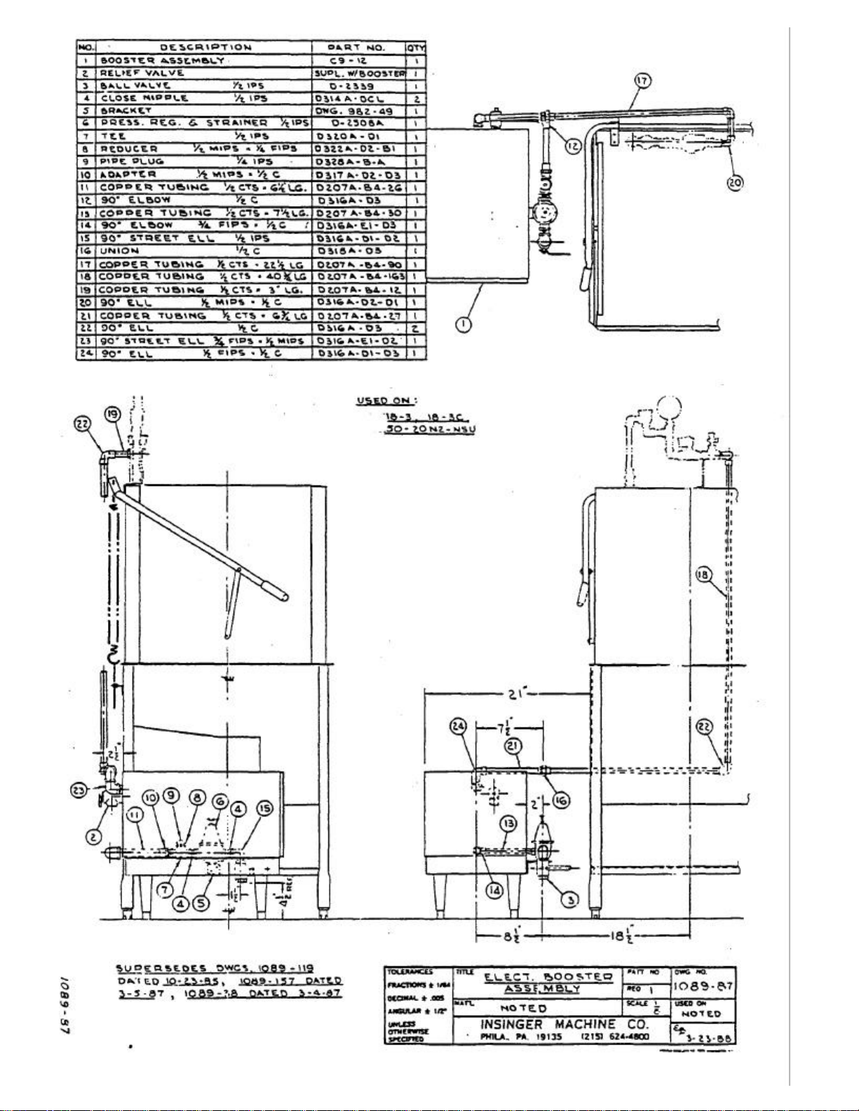
1 BOOSTER ASSEMBLY 721-30 1
2
90° UNION ELBOW 1/2" C.
3
90° UNION ELBOW 1/2" C X 1/2" MIPS,
4
90° ELBOW 1/2"C
5 ADAPTER. 1/2" C X 1/2" MIPS D317F -D3-D2 1
6 COPPER TUBING 1/2"CTS X 3" LG D207A-B4-12 1
7 COPPER TUBING 1/2''CTS X 43" LG D207A-B4-172 1
8 COPPER TUBING 1/2''CTS X 21 1/2" LG D207A-B4-86 1
9 COPPER TUBING 1/2''CTS X 18" LG D207A-B4-72 1
10 TEE 3/4 FIPS X 1/2 FIPS X 3/4 FIPS D320F -D1E1E1 1
11 PRESSURE RELIEF VALVE 3/4 MIPS D2507 1
12 COPPER. PIPE 3/4 IPS X 4" LG D314A-ES-32 1
DESCRIPTION PART NO.
D319F -D3-D3 1
D319F -D3-D2 1
D3116F -D3-D3 2
QTY


NO. DESCRIPTION PART NO. QTY.
1 LOCKNUT. HEX 1/2 IPS D326F -D1 1
2 NIPPLE. CLOSE 1/2 IPS D314F -DC-00 2
3 TEE 1/2 IPS D320F -D1D1D1 3
4 PLUG. PIPE 1/2 IPS D328F -D2-A 1
5 UNION. STRAIGHT 1/2 IPS D318F -D1-01 1
6 NIPPLE. PIPE 1/2 IPS x 4 ½’' LG. D314F--DS-36 1
7 ELBOW. 90° STREET 1/2 IPS D315F -D2-01 2
8 BREAKER. VACUUM 1/2 IPS D-2241A 1
9 NIPPLE. PIPE 1/2 IPS x 2’' LG. D314F-D5-16 2
10 REDUCER. HEX 1/2 HIPS x 1/4 FIPS D322F -D2-B1 2
11 GAUGE. TEMPERATURE 1/4 IPS D-2495R 1
12 ELBOW. 90° 1/2 IPS D316F-D1-01 1
13 NIPPLE. PIPE 1/2 IPS x 4’’ LG. D314F-D5-32 1
14 BRACKET. PIPING SUPPORT DWG. 951-79 1
15 PETCOCK 1/4 IPS D2497 1
16 GAUGE. PRESSURE 1/4 IPS SK-1433 1
17 TEE 1/2 IPS [ D320E -D1D1D1 1
18 NIPPLE. CLOSE 1/2 IPS [ D314E -DC-00 1
19 ADAPTER 1/2 MIPS x 1/2 C [ D317E -D3-02 2
20 TUBING. S/S 1/2 CTS x 9’' LG. D207C -B4-36 1
21 UNION 1/2 FIPS x 1/2 C [ D318E -D3-01 2
22 REDUCER. FLUSH 1/2 MIPS x 3/8 FIPS [ D323E -D2-C1 2
23 VALVE. BALL CHECK 1/2 IPS [ D-2453J 1
24 TUBING. S/S 1/2 CTS x 26 1/2'’ LG. D207C -B4-105 1
25 ELBOW. 90° 1/2 C [ D316E-DJ-DJ 1
26 TUBING. S/S 1/2 CTS x 9 ¾’' LG. D207C -B4- 39 1
27 ASS'Y. SPINNING SPRAY PIPE (WASH) DWG. 1089-25 2
28 ASS'Y. SPINNING SPRAY PIPE (RINSE) DWG. 1089-26 2
29 SCREW, LOCKING D2-584 2


18-3 GAS HEAT WITH HOT SURFACE IGNITION
Hot surface element heats
Volts to valve.
t
does not heat, but
This dishwasher is heated by natural gas or propane (L.P. gas). A fully
electronic Hot Surface Ignition (H.S.I) system with internal flame sensor is used - no
manual pilot. The wash temperature board thermostat controls burner operation, with low
water cut-out switches as back-up.
SERVICE CHECKS
Symptom Cause/Cure
1) Dead. A) No 24 Volt Input.
B) Check system wiring.
C) Check thermostat,
transformer, high temp
limit switch, circuit
breaker, etc.
2)
up, but zero voltage
at valve during
A) Check wiring valve and
module.
B) Check power to valve.
trial-for-ignition.
3) Hot surface element heats.
24
A) Check ground in system 24
Volt supply.
Flame established,
but does not stay on. B) Hot surface element
improperly located.
C) Check all wiring
connections.
D) Burner out of adjustment.
4) Hot surface element A) Gas supply off.
heats. 24 Volts to B) Check gas valve.
valve. System fails to
ignite.
C) Burner out of adjustment
(orifice plugged).
D) Hot surface element
incorrectly located.
5) Hot surface elemen
A) Check for broken or
cracked hot surface
unit cycles.
element.

(SEE GENERAL ARRANGEMENT DWG. FOR COMPONENT LOCATIONS)
Hot Surface Ignition Module -
24 VAC, 4 second heat-up time, 7 second trial for ignition. Loss of flame will result in
one re-try for ignition. This unit cannot be repaired - it must be replaced. Flame current .75
micro amp minimum.
Gas Valve -
This valve is equipped with a redundant solenoid valve, that controls gas flow to the pilot and
main burners, a relay -operated main valve that controls gas flow to the main burner, a pressure
regulator to maintain a constant outlet pressure, and a two-position gas cock knob for manual gas
shut-off. Both redundant and main valves open together due to the jumper wire installed between
terminals M-1 and P-3.
The gas outlet pressure is stamped on a metal nameplate inside the burner box. This should
be checked using a manometer at the pressure tap on the outlet of the valve. Remove 1/8" pipe plug
with an allen wrench (not brass hex fitting) to install test fitting.
The gas supply to the valve can be checked using a manometer at the pressure tap on the
inlet of the valve. Shut off gas downstream before removing 1/8" pipe plug to install test fitting.
Hot Surface Element (Ignitor) -
This consists of a silicon carbide heater blade cemented into a ceramic holder with a metal
mounting plate mechanically attached. The ceramic extends 3/4" past the mounting plate into the
burner. The wide surface of the blade must face the burner surface.
To check operation, shut off gas supply. The glow of the ignitor during the heat -up and trialfor-ignition periods can be seen through the viewport (look up from ground level). If no glow can be
seen, a cracked blade or or bad blade to wire joint is possible. Disconnect wire leads and measure
resistance at room temperature (1 to 6 ohms) .

 Loading...