

Page 1

User Guide | Guide de l’utilisateur | Guía del Usuario
Car Amplifier
Amplificateur de voiture | Amplificador para el auto
NS-A1200
Page 2

Page 3

Contents
Welcome. . . . . . . . . . . . . . . . . . . . . . . . . . . . . . . . . . . . . . . . . .3
Introduction . . . . . . . . . . . . . . . . . . . . . . . . . . . . . . . . . . . . . . . .3
Safety information. . . . . . . . . . . . . . . . . . . . . . . . . . . . . . . . . . .4
Features . . . . . . . . . . . . . . . . . . . . . . . . . . . . . . . . . . . . . . . . . .5
Installing your amplifier . . . . . . . . . . . . . . . . . . . . . . . . . . . . . . .9
Using your amplifier . . . . . . . . . . . . . . . . . . . . . . . . . . . . . . . .13
Troubleshooting. . . . . . . . . . . . . . . . . . . . . . . . . . . . . . . . . . . .15
Specifications . . . . . . . . . . . . . . . . . . . . . . . . . . . . . . . . . . . . . 16
Legal notices. . . . . . . . . . . . . . . . . . . . . . . . . . . . . . . . . . . . . .17
Warranty . . . . . . . . . . . . . . . . . . . . . . . . . . . . . . . . . . . . . . . . .19
Français . . . . . . . . . . . . . . . . . . . . . . . . . . . . . . . . 21
Español. . . . . . . . . . . . . . . . . . . . . . . . . . . . . . . . . 41
Welcome
Congratulations on your purchase of a high-quality Ins ig nia produ ct .
Your NS-A2200 represents the state of the art in car amplifier design,
and is designed for reliable and trouble-free performance.
Insignia NS-A1200
Car Amplifier
Introduction
This amplifier provides high-performance sound enhancement for
your mobile audio equipment. Its versatility provides compatibility with
additional equalizers, frequency-dividing network crossovers, and
other audio processors in a customized system. The multi-mode
bridging capabilities allow flexibility in hosting many different speaker
configurations.
Important
For optimum performance, we recommend that you read
this user guide before beginning installation.
www.insignia-products.com
3
Page 4

Safety information
• Make sure that your stereo and other audio equipment is
turned off while connecting the input jacks and speaker
terminals of your amplifier.
• The +12 volt DC power wire must be fused at the battery
positive (+) terminal connection. Before making or breaking
power connections at this system’s power terminals,
disconnect the +12V wire at the battery end.
• Because of the amplifier’s power requirements, the amplifier’s
power connection should be made directly to the battery’s
positive (+) terminal. For safety, install an in-line fuse holder
(not included) as close to the battery’s positive (+) terminal as
possible. The fuse should have an ampere rating not
exceeding the total value of the fuses in the amplifier.
• Thoroughly investigate the layout of your vehicle before drilling
or cutting any holes. Tak e extra precautions when working near
tanks, lines, hydraulic lines, and electrical wiring. Don’t mount
this system so that the wire connections are unprotected or are
subject to pinching or damage from nearby objects.
• The amplifier produces a large amount of heat, and that heat
must be dissipated correctly or the amplifier will turn off to
prevent damage. Do not enclose the amplifier in a small box or
cover it so that air cannot flow around the cooling fins. If
mounting it in a trunk, mount it vertically.
• If you need to replace the power fuse, replace it only with a
fuse identical to that supplied with the system. Using a fuse of
a different type or rating may result in damage to this system,
which isn’t covered by the warranty.
• If the Protect LED is on, carefully check the system t o
determine what has caused the protection circuit to engage.
The amplifier can be reset by turning the remote power off and
then on again. If the amplifier shut down because of thermal
overload, allow it to cool down before restarting. If the amplifier
shut down because of an input overload or short circuit, repair
these conditions before trying to turn the amplifier on again.
• Continued exposure to excessively high volume sound levels
may cause hearing loss or damage. Operation of a motor
vehicle while listening to audio equipment at high volume levels
may impair your ability to hear external sounds such as horns,
warning signals, or emergency vehicles, which could create a
traffic hazard.
Insignia NS-A1200 Car Amplifier
4
www.insignia-products.com
Page 5
Insignia NS-A1200 Car Amplifier
Features
• High-speed digital circuitry
• Fully regulated PWM power supply
• Four-way protection circuit
•1 Ω stability
• Bridging synchronization
• Variable low pass: 50 Hz ~ 150 Hz
• Variable subsonic filter: 15 Hz ~ 40 Hz
• Phase switch: 0° ~ 180°
• System distress indicator
• Mono speaker output connector
• Remote dash mount low-level gain control with cable
• Nickel-plated heavy-duty power and speaker terminals
Controls and functions
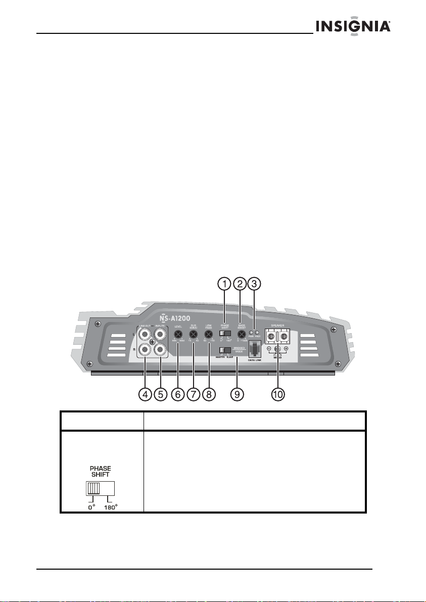
Front view
Item Description
1 PHASE
SHIFT
control
Slide this switch to either 0° or 180° to change the
phase of your subwoofer to help compensate for
timing differe nc es betw e en drivers.
www.insignia-products.com
5
Page 6
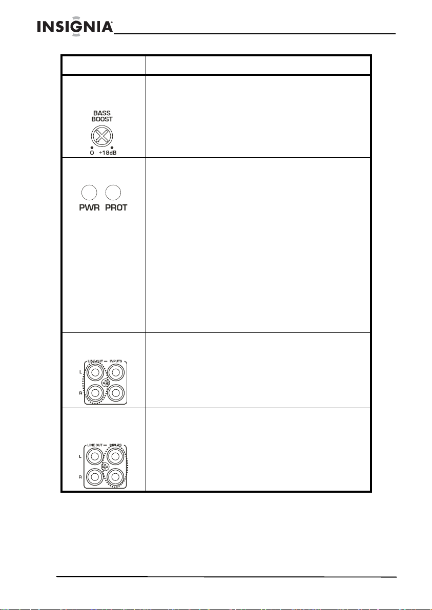
Item Description
2 BASS
BOOST
control
Adjust this control with a screwdriver to emphasize
bass notes at 35Hz~80 Hz by as much as 18 dB.
Insignia NS-A1200 Car Amplifier
3 LED
indicators
4 Low-level out
RCA jacks
5 Low-level
input RCA
jacks
PWR (Power)—This green LED turns on when the
amplifier is turned on. If it fails to turn on, check the
power connections to the amplifier and fuses.
Protect—This LED turns on when the amplifier’s
protection circuitry disab le s the am pli fie r if input
overload, short circuit, or extremely high temperature
conditions are detected. When the LED is on, it
indicates that the amplifier has gone into a
self-preservation mode.
If the Protect LED is on, ca refully c heck the syste m to
determine what has caused the protection circuit to
engage. The amplifier can be reset by turning the
remote power off and then on again. If the amplifier
shut down because of thermal overload, allow it to
cool down bef ore restarting. If the am plifie r shut do wn
because of an input overload or short circuit, repair
these conditions before trying to turn the amplifier on
again.
In a multiple-amplifier system, connect RCA cables
from these jacks to the LINE IN jacks on the
secondary amplifier. With these jacks, splitter cords
are not necessary.
Connect high-quality, shielded RCA cables to the
source devi ce and these jacks.
6
www.insignia-products.com
Page 7
Insignia NS-A1200 Car Amplifier
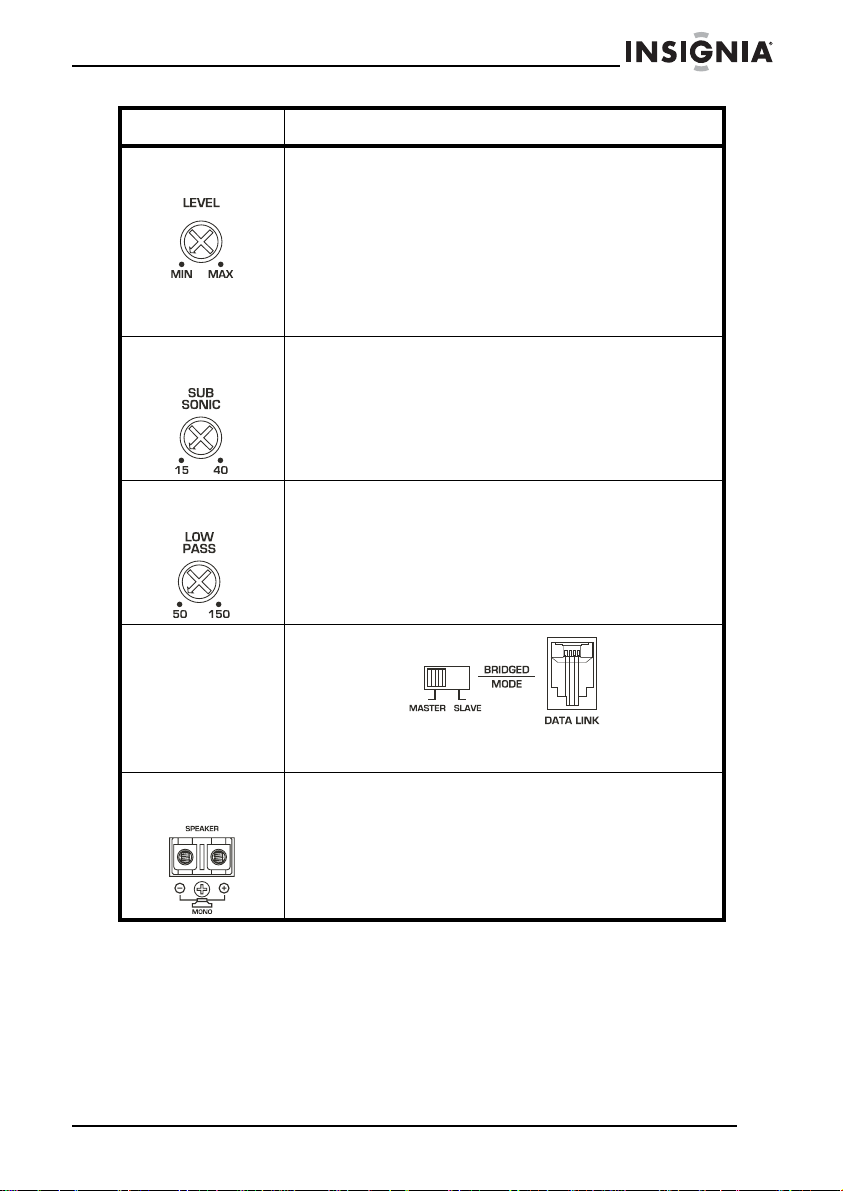
Item Description
6 Input LEVEL
control
7 SUBSONIC
filter control
Adjust this control with a screwdriver to change the
amplifier's input sensitivity. Input sensitivity is variable
from 200 mV to 8 V. Clockwise increases sensitivity,
and counter-clockwise decreases sensitivity. The
amplifier can be driv en to full pow er with a wid e rang e
of signal levels. A lower signal level will require
increased sensitivity for full power. A higher signal
level will require decreased sensitivity. Avoid setting
the sensitivity lower than necessary, because doing
so would introduce unwanted distortion.
Adjust this control with a screwdriver to roll off all
unwanted frequencies below 15 Hz~40 Hz. This will
allow the amplifier to use that wasted power on the
audible bandw idth.
8 LOW PASS
filter control
9 BRIDGED
MODE switch
10 Speaker
terminals
Adjust this control with a screwdriver to set the
low-pass frequency (50~150 Hz). The filter cuts off
frequencies above the set point. In general, the
selected frequen cy shoul d close ly match the reson ant
frequency of the speaker box. (The resonant
frequency is the frequen cy be lo w whic h sou nd can not
be reproduced by the speaker.)
Slide this switch to MASTER or SLAVE for a
multiple-amplifier setup.
Make sure that the negative side of the voice coil is
connected to the (-) term inal and the positive side of
the voice coil is connected to the (+) terminal.
www.insignia-products.com
7
Page 8
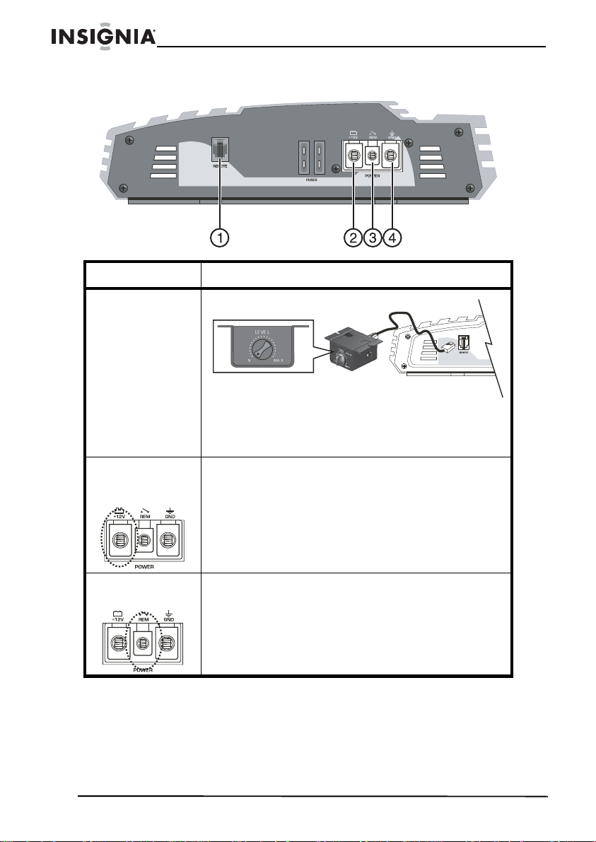
Rear view
Item Description
1 Remote bass
boost control
2 B+ terminal
(battery
positive +)
Insignia NS-A1200 Car Amplifier
Remote bass boost control: NS-R M
Plug this control into the REMOTE jack on the
amplifier , th en moun t the con trol in a n easy -to-acc ess
location. Adjust this control to change the bass boost
gain for the amplifier’s speaker output (0 ~ 18 dB).
Because of the amplifier’s power requirements, this
connection should be made directly to the battery’s
positive (+) terminal. For safety, install an in-line fuse
holder (not included) as close to the battery’s
positive (+) terminal as possible. The fuse should
have a n ampere rating n ot exc eeding the to tal value o f
the fuses in the amplifier.
3 Remote
power on
8
Connect your remo te antenna or amplifier lead to this
input to automatically turn on your amplifier when the
radio is turned on.
www.insignia-products.com
Page 9
Insignia NS-A1200 Car Amplifier
Item Description
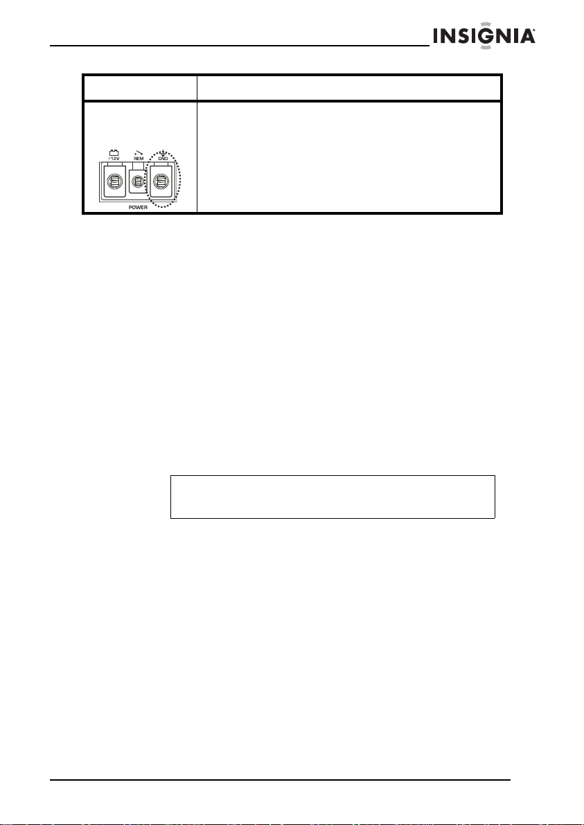
4 B- terminal
(chassis
ground)
To avoid unwanted ignition noise caused by ground
loops, the amplifier must be grounded to a clean,
bare, metal surface of the vehicle’s chassis. The
ground wire should not be more than three feet
(one meter) long.
Installing your amplifier
Planning your system
Before beginning the installation, consider the following:
• If you plan to expand your system by adding other components
sometime in the future, make sure that adequate space is
provided and that cooling requirements are met.
• Consider whether you should use high or low inputs. Your
amplifier has been designed to accept a low-level (pre-amp
output from your stereo) signal source. If your source device is
equipped with pre-amp outputs, you can use them to drive the
amplifier, so you can connect the amplifier to the two rear
speakers. Then you can use the built-in power of your source
device to drive the two front speakers.
Note
Distortion level is considerably lower from pre-amp (low
level) outputs.
• Make sure that your components are adequately matched. The
peak power rating of your speakers must be equal to or greater
than the amplifier’s. They also must be 1-8 Ω impedance. You
can find the speaker’s impedance rating by looking on the
speaker magnet.
and
• Consider the length of your leads (wires)
determining the amplifier’s mounting location. Pre-amp input
jacks require a length of high-quality, shielded, male-to-male
RCA patch cable.
www.insignia-products.com
the routing when
9
Page 10

Mounting your amplifier
The mounting position of your amplifier will have a great effect on its
ability to dissipate the heat generated during normal operation. It has
an ample heat sink for heat dissipation, and is also designed with a
thermal shut-down circuit (for heat protection). Directing air flow over
the cooling fins will dramatically improve heat dissipation. Do not
enclose the amplifier in a small box or cover it so that air cannot flow
around the cooling fins.
Temperatures in car trunks have been measured as high as 175°F
(80°C) in the summer. Since the thermal shut-down point for the
amplifier is 185°F (85°C), it must be mounted in a location that allows
for maximum cooling capability. For maximum convective air flow in
an enclosed trunk, mount the amplifier in a vertical position or on a
vertical surface.
Cooling requirements are considerably relaxed when mounting inside
the passenger compartment, since the driver does not often allow
internal temperatures to reach the thermal shut-down point. Floor
mounting under the seat is usually sufficient, as long as there is at
least 1 inch (about 2 cm) above the amplifier’s cooling fins for
ventilation.
To mount the amplifier:
1 Select a suitable location that is convenient for mounting, is
accessible for wiring, and has adequate room for air circulation
and cooling.
2 Use the amplifier as a template to mark the mounting holes.
3 Drill the four mounting holes.
Insignia NS-A1200 Car Amplifier
Caution
Use extreme caution while preparing to drill holes. Carefully
inspect underneath the surface before drilling.
4 Secure the amplifier using the screws provided.
Connecting the power
Caution
Disconnect the vehicle’s battery before connecting to the
+12 Volts supply wiring.
We recommend 4 gauge (SL-2000D/2600D/3400D) wire (thicker if
planning for additional amplifiers) for both the power and the ground
wires. We recommend 12 gauge for the remote turn-on wire. Both
types are available at most mobile audio dealers or installation shops.
10
www.insignia-products.com
Page 11
Insignia NS-A1200 Car Amplifier
To connect the power:
1 Connect the ground wire to the vehicle’s chassis. To avoid ignition
noise caused by ground loops, the amplifier must be grounded to
a clean, bare, metal surface of the vehicle’s chassis.
Note
Ground wire should not be more than three feet
(one meter) long.
2 Connect the +12 volt (fused) constant power cable to the battery’s
positive (+) terminal.
Because of the amplifier’s power requirements, this connection
should be made directly to the battery’s positive (+) terminal. For
safety, install an in-line fuse holder (not included) as close to the
battery’s positive (+) terminal as possible. The fuse should have
an ampere rating that does not exceed the total value of fuses in
the amplif ier.
3 Connect the remote turn-on input to the power antenna output of
your car stereo. This amplifier is turned on whenever the vehicle’s
stereo is turned on.
Note
If your radio does not have a +12 volt output lead when the
radio is turned on, the REM terminal on the amplifier can be
connected to the vehicle’s accessory circuit that is live when
the ignition key is on.
Warning
Thoroughly investigate the layout of your vehicle before
drilling or cutting any holes. Take extra precautions when
working near tanks, lines, hydraulic lines, and electrical
wiring. Don’t mount this system so that the wire connections
are unprotected or are subject to pinching or damage from
nearby objects.
The +12 volt DC power wire must be fused at the battery
positive (+) terminal connection. Before making or breaking
power connections at this system’s power terminals,
disconnect the +12V wire at the battery end.
Make sure that your stereo and other audio equipment is
turned off while connecting the input jacks and speaker
terminals of your amplifier.
If you need to replace the power fuse, replace it only with a
fuse identical to that supplied with the system. Using a fuse
of a different type or rating may result in damage to this
system, which isn’t covered by the warranty.
www.insignia-products.com
11
Page 12
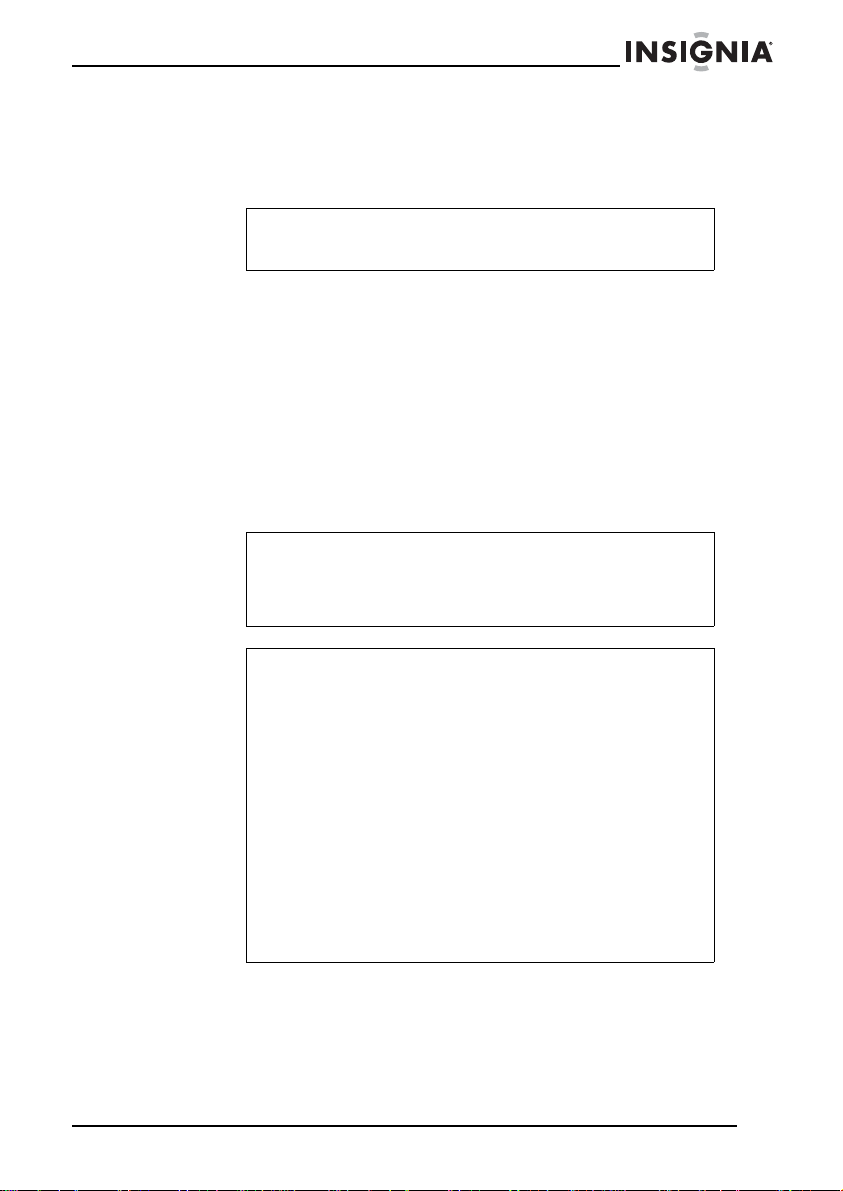
Connecting the speakers
Single-amplifier system
Front view
Insignia NS-A1200 Car Amplifier
To inputs of satellite
amplifier system
Rear view
In-line fuse holder
Battery
From outputs of
source device
Distribution
block
Woofer
Ground
To remote turn-on
from source device
Capacitor
12
www.insignia-products.com
Page 13
Insignia NS-A1200 Car Amplifier
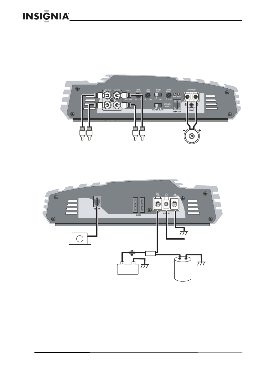
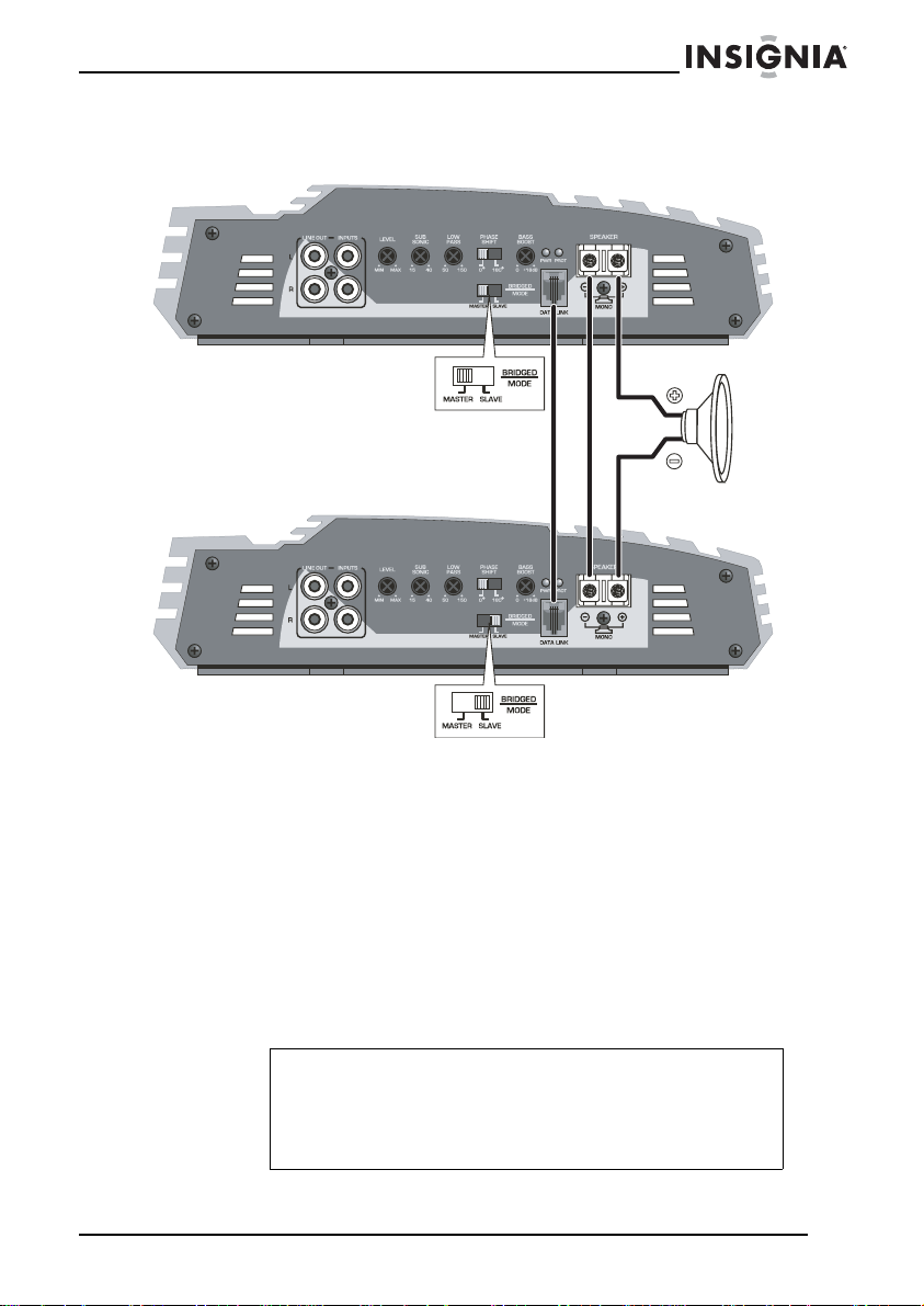
Bridging two amplifiers
Master amp
Bridged swit ch:
Master position
Slave amp
Bridged swit ch:
Using your amplifier
Turning on the amplifier
The amplifier automatically turns on a few seconds after you turn your
vehicle’s ignition switch to ACC or ON or turn on your sound system,
depending upon how you wired the system. The POWER indicator on
the top of the amplifier turns on when the amplifier is on.
Slave position
Speaker
impedence:
Ω
2
Note
Your amplifier requires 90 amps or more of power from your
vehicle’s battery during operation. To protect your battery
from discharging to the point that you cannot start your
vehicle, do not operate the amplifier unless your vehicle is
running.
www.insignia-products.com
13
Page 14
Adjusting the audio level by ear
For best performance, you must match the amplifier’s input sensitivity
to your source’s maximum output level (also called “gain matching”).
The LEVEL (gain) control located on the side of the amplifier is
designed to do this. It is not a volume control. It adjusts the incoming
signal level so that the source device and the amplifier reach
maximum output at the same time. This ensures that maximum
system volume is achieved with minimal distortion.
Warning
High-powered audio systems in a vehicle are capable of
generating “live concert” levels of sound pressure.
Continued exposure to excessively high volume sound
levels may cause hearing loss or damage. Operation of a
motor vehicle while listening to audio equipment at high
volume levels may impair your ability to hear external
sounds such as horns, warning signals, or emergency
vehicles, which could create a traffic hazard.
To adjust the audio level:
1 Turn the LEVEL (gain) control fully counterclockwise to MIN.
2 Play full-frequency music that has continuously high levels
(FM pop music is a good choice).
3 Turn up the source device’s volume control until just before you
hear the source device’s distortion, or at 90% of full output
(whichever comes first).
4 Slowly turn the LEVEL (gain) control clockwise until just before
you hear amplifier or speaker distortion, or until you reach a
maximum comfortable listening level (whichever comes first).
5 Turn the source device’s volume control back down to a
comfortable listening level.
Insignia NS-A1200 Car Amplifier
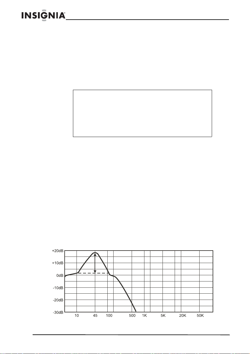
Adjusting bass boost
14
www.insignia-products.com
+18 dB
@45 Hz
Page 15
Insignia NS-A1200 Car Amplifier
The BASS BOOST control raises the amplifier output up to 18 dB at
frequencies tightly centered around 45 Hz. This “bump” can have a
dramatic effect on the bass system’s apparent volume. Use caution
when adjusting this control, as subwoofer damage may result if the
subwoofer begins to distort. When you exceed the subwoofer’s
capabilities, the distortion will be obvious.
To adjust bass boost:
1 Rotate the BASS BOOST control counter-clockwise until it points
at 0. Use a screwdriver to adjust the BASS BOOST co ntr o l on t h e
amplifier, or adjust the remote BASS BOOST control by hand.
Caution
Adjusting the bass boost should be done with caution, so
that the woofer cone throw’s maximum excursion is not
reached. Adjust to the woofer’s best performance level (best
bass performance where no distortion is present), then
reduce the bass boost slightly.
2 Play some music, and adjust the source device’s volume and the
amplifier’s LEVEL (gain) control to a comfortable listening level.
3 Slowly rotate the BASS BOOST control clockwise until it sounds
the way you want.
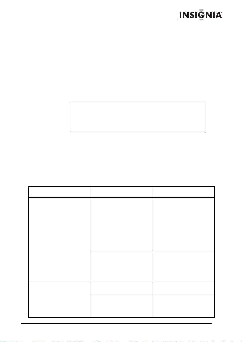
Troubleshooting
Symptom Cause Solution
No sound. If the PWR LED is off,
Amplifier is not turning
on.
fuses may be blown,
remote lead may be
disconnected, source
leads may be
disconnected, gain
control may be set t oo
high or low, or source
device’s volume may be
set too low.
If the Protect LED is on,
there may be a speaker
short circuit, or the
amplifier ma y have
overheated.
No power is available to
the amplifier.
No power to remote wire
with the source device
on.
Check fuses in amplifier
and on power lea d. Mak e
sure the remote lead is
connected. Chec k source
signal leads. Check gain
control. Check the source
device’s volume level.
Check for speaker short
circuits. Make sure the
amplifier is not
overheating.
Check the power wire or
connections.
Check connections to the
source device. Check
fuses and replace if
necessary.
www.insignia-products.com
15
Page 16
Insignia NS-A1200 Car Amplifier
Symptom Cause Solution
No sound in one channel. Speaker short circuits,
Amplifier turns off at
medium or high volumes.
Protect LED is on. Overheated amplifier. Turn source device’s
disconnected speaker
cables.
Mismatch with speaker
load impedance.
Speaker cable short
circuit.
Check speaker leads for
short circuits or
disconnected cables.
Reverse the LEFT and
RIGHT RCA inputs to
determine if the loss is
occurring before the
amplifier.
Check speaker load
impedance. Make sure
that you have followed
correct speaker load
impedance
recommendations . (If you
used an ohm meter to
check speaker
resistance, remember
that DC resistance and
AC impedance may not
be the same.)
volume down. Relocate
the amplifier to a better
ventilated place.
Separate all speaker
wires, and make sure
they are insulated.
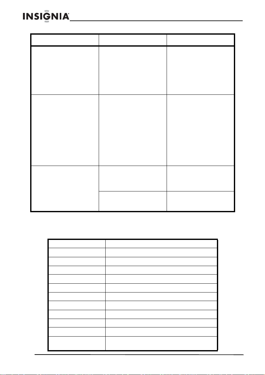
Specifications
4 Ω 150W × 1 channel, @1% THD
Ω 225W × 1 channel, @1% THD
2
1
Ω 400W × 1 channel, @1% THD
Signal-to-noise ratio 100 dB
Frequency response 15 Hz ~ 150 Hz
Variable low pass 50 Hz ~ 150 Hz
Va riable subsonic 15 Hz ~ 40 Hz
Variable bass boost 0 ~ +18 dB
Phase control 0° ~ 180°
Input sensitivity 200 mV to 8 V
Input impedance 10K
Line output
impedance
16
Ω
100 Ω
www.insignia-products.com
Page 17

Insignia NS-A1200 Car Amplifier
Dimensions 10.31 × 2.75 × 9.84 inches
Fuse rating 25A (2)
Legal notices
FCC Part 15
This device complies with Par t 15 of the FCC Rules. Operation of this product is
subject to the following two conditions: (1) this device may not cause harmful
interference, and (2) this device must accept any interference received, including
interference that may cause undesired operation.
FCC warning
Changes or modifications not expressly approved by the party responsible for
compliance with the FCC Rules could void the user’s authority to operate this
equipment.
RSS 310 statement
To reduce potential radio interference to other users, the antenna type and its gain
should be so chosen that the equivalent isotropically radiated power (e.i.r.p.) is not
more than that permitted for successful communication.
Copyright
© 2007 Insignia. Insignia and the Insignia logo are trademarks of Best Buy Enterprise
Services, Inc. Other brands and product names are trademarks or registered
trademarks of their respective holders. Specifications and features are subject to
change without notice or obligation.
For service and support call (877) 467-4289.
(261.9 × 69.9 × 249.9 mm)
www.insignia-products.com
17
Page 18

Insignia NS-A1200 Car Amplifier
18
www.insignia-products.com
Page 19

Insignia NS-A1200 Car Amplifier
Warranty
90-day limited warranty
Insignia Products (“Insignia”) warrants to you, the original purchaser of this new
NS-A1200 (“Product”), that the Product shall be free of defects in the original
manufacture of the material or workmanship for a period of 90 days from the date of
your purchase of the Product (“Warranty Period”). This Product must be purchased
from an authorized dealer of Insignia brand products and packaged with this warranty
statement. This warranty does not cover refurbished Product. If you notify Insignia
during the Warranty Period of a defect covered by this warranty that requires service,
terms of this warranty apply.
How long does the coverage last?
The Warranty Period lasts for 90 days from the date you purchased the Product. The
purchase date is printed on the receipt you received with the Product.
What does this warranty cover?
During the Warranty Period, if the original manuf act ure of the material or workmanship
of the Product is determined to be defective by an authorized Insignia repair center or
store personnel, Insignia will (at its sole option): (1) repair the Product with new or
rebuilt parts; or (2) replace the Product at no charge with new or rebuilt comparable
products or parts. Products and parts replaced under this warranty become the
property of Insignia and are not returned to you. If service of Products or parts are
required after the Warranty Period expires, you must pay all labor and parts charges.
This warranty lasts as long as you own your Insignia Product during the Warranty
Period. Warranty coverage terminates if you sell or otherwise transfer the Product.
How to obtain warranty service?
If you purchased the Product at a retail store location, take y our original receipt and the
Product to the store you purchased it from. Make sure that you place the Product in its
original packaging or packaging that provides the same amount of protection as the
original packaging. If you purchased the Product from an online web site, mail your
original receipt and the Product to the address listed on the web site. Make sure that
you put the Product in its original packaging or packaging that provides the same
amount of protection as the original packaging.
Where is the warranty valid?
This warranty is valid only to the original purchaser of the product in the United States
and Canada.
What does the warranty not cover?
This warranty does not cover:
• Customer instruction
• Installation
• Set up adjustments
• Cosmetic damage
• Damage due to acts of God, such as lightning strikes
• Accident
•Misuse
•Abuse
• Negligence
• Commercial use
www.insignia-products.com
19
Page 20

Insignia NS-A1200 Car Amplifier
• Modification of any part of the Product, including the antenna
This warranty also does not cover:
• Damage due to incorrect operation or maintenance
• Connection to an incorrect voltage supply
• Attempted repair by anyone other than a facility authorized by Insignia to service
the Product
• Products sold as is or with all faults
• Consumables, such as fuses or batteries
• Products where the factory applied serial number has been altered or removed
REPAIR REPLACEMENT AS PROVIDE D UNDER THIS WARRANTY IS YOUR
EXCLUSIVE REMEDY. INSIGNIA SHALL NOT BE LIABLE FOR ANY INCIDENTAL
OR CONSEQUENTIAL DAMAGE S FOR THE BREA CH OF ANY EXPRESS OR
IMPLIED WARRANTY ON THIS PRODUCT, INCLUDING, BUT NOT LIMITED TO,
LOST DATA, LOSS OF USE OF YOUR PRODUCT, LOST BUSINESS OR LOST
PROFITS. INSIGNIA PRODUCTS MAKES NO OTHER EXPRESS WARRANTIES
WITH RESPECT TO THE PRODUCT, ALL EXPRESS AND IMPLIED WARRANTIES
FOR THE PRODUCT, INCLUDING, BUT NOT LIMITED TO, ANY IMPLIED
WARRANTIES OF AND CONDITIONS OF MERCHANTABILITY AND FITNESS FOR
A PARTICULAR PURPOSE, ARE LIMITED IN DURATION TO THE WARRANTY
PERIOD SET FORTH ABOVE AND NO WARRANTIE S, WH ET HER EXPRESS OR
IMPLIED, WILL APPLY AFTER THE WARRANTY PERI OD. SOME STATES,
PROVI NCES AND JURISDICTIONS DO NOT ALLOW LIMITATI ONS ON HO W LONG
AN IMPLIED WARRANTY LASTS, SO THE ABOVE LIMITATION MA Y NO T APPLY TO
YOU. THIS WARRANTY GIVES YOU SPECIFIC LEGAL RIGHTS, AND YOU MAY
ALSO HAVE OTHER RIGHTS, WHICH VARY FROM STATE TO STATE OR
PROVINCE TO PROVINCE.
20
www.insignia-products.com
Page 21

Insignia NS-A1200 Amplificateur de voiture
Insignia NS-A1200
Amplificateur de voiture
Table des matières
Bienvenue. . . . . . . . . . . . . . . . . . . . . . . . . . . . . . . . . . . . . . . .21
Introduction . . . . . . . . . . . . . . . . . . . . . . . . . . . . . . . . . . . . . . .21
Informations sur la sécurité. . . . . . . . . . . . . . . . . . . . . . . . . . . 22
Fonctionnalités . . . . . . . . . . . . . . . . . . . . . . . . . . . . . . . . . . . .23
Installation de l'amplificateur. . . . . . . . . . . . . . . . . . . . . . . . . .28
Utilisation de l’amplificateur . . . . . . . . . . . . . . . . . . . . . . . . . .34
Problèmes et solutions . . . . . . . . . . . . . . . . . . . . . . . . . . . . . .36
Spécifications . . . . . . . . . . . . . . . . . . . . . . . . . . . . . . . . . . . . . 37
Avis juridiques. . . . . . . . . . . . . . . . . . . . . . . . . . . . . . . . . . . . . 38
Garantie . . . . . . . . . . . . . . . . . . . . . . . . . . . . . . . . . . . . . . . . .39
Bienvenue
Félicitations d’avoir acheté ce produit Ins ign ia de haute quali té. Le
modèle NS-A2200 représente le nec plus ultra de la technologie dans
la conception des amplificateurs de voiture et a été conçu pour des
performances et une fiabilité exceptionnelles.
Introduction
Cet amplificateur fournit une amélioration des performances sonores
de l'équipement audio des voitures. Sa polyvalence fournit une
excellente compatibilité avec des égalisateurs supplémentaires,
répartiteurs en réseau de division de fréquence et autres systèmes
de traitement audio dans un système personnalisé. Les capacités de
dérivation en multi-mode permettent une grande souplesse de
configuration d'installation de nombreux haut-parleurs différents.
Important
Pour des performances optimisées, il est recommandé de
lire ce guide de l'utilisateur avant de commencer
l'installation.
www.insignia-products.com
21
Page 22

Insignia NS-A1200 Amplificateur de voiture
Informations sur la sécurité
• Vérifier que l'équipement stéréo et les autres équipements
audio sont hors tensions lors de la connexion des prises
d'entrée et des bornes des haut-parleurs de l'amplificateur.
• Le câble d'alimentation en + 12 volts continus doit comprendre
un fusible au niveau de la connexion positive (+) de la batterie.
Avant de réaliser les connexions ou d'interrompre
l'alimentation sur les bornes concernées du système,
déconnecter le câble + 12 V de la batterie.
• C'est en raison des impératifs d'alimentation de l'amplificateur
que les connexions doivent être directement réalisées sur la
borne positive (+) de la batterie. À titre de sécurité, installer un
porte-fusible en ligne (non inclus) aussi près que possible de la
borne positive (+) de la batterie. Le fusible doit être calibré
pour ne pas dépasser la valeur totale de tous les fusibles de
l'amplificateur.
• L'utilisateur devra faire des recherches sur l'implantation des
composants du véhicule avant de forer un trou ou d'effectuer
une découpe. Prendre toutes les précautions en travaillant à
proximité des réservoirs, des tuyauteries, des tuyauteries
hydrauliques et des câbles électriques. Ne pas monter ce
système de façon telle que les connexions des câbles
manquent de protection ou puissent subir des détériorations
ou des pincements en raison des objets avoisinants.
• L'amplificateur produit une grande quantité de chaleur qui doit
être correctement dissipée sinon il se mettra de lui-même hors
tension. Ne pas enfermer l'amplificateur dans un petit boîtier
ou le recouvrir de sorte que le débit d'air ne puisse rencontrer
les ailettes de refroidissement. S’il est monté dans un coffre, il
le sera verticalement.
• Si le fusible d'alimentation doit être remplacé, il ne le sera
qu'avec un fusible identique à celui fourni avec le système.
L'utilisation d'un fusible de type ou de capacité différents
pourrait endommager le système et annuler la garantie.
•Si la DEL Protect (protection) est allumée, vérifier avec
précaution le système afin de déterminer ce qui a provoqué la
mise en route du circuit de protection. L'amplificateur peut être
réinitialisé en mettant hors tension, puis sous tension
l'alimentation distante. Si l'amplificateur arrête son
fonctionnement en raison d'une surcharge thermique, lui
laisser le temps de se refroidir avant de le redémarrer. Si
l'amplificateur arrête son fonctionnement en raison d'une
surcharge à l'entrée ou d'un court-circuit, ces conditions
doivent être réparées avant d'essayer de remettre
l'amplificateur en fonctionnement.
22
www.insignia-products.com
Page 23

Insignia NS-A1200 Amplificateur de voiture
• Être exposé continuellement à de puissants volumes sonores
peut être à l'origine de détériorations ou de pertes auditives Le
fonctionnement d'un véhicule motorisé tout en écoutant un
équipement radio à des volumes élevés peut empêcher le
conducteur d'entendre les bruits extérieurs tels que les
klaxons, les signaux d'avertissement ou les véhicules
d'urgence, ce qui pourrait être dangereux pour le trafic.
Fonctionnalités
• Circuits numériques à grande vitesse
• Alimentation à impulsions complètement régulée
• Circuit de protection à quatre voies
•1 Ω stabilité
• Synchronisation de dérivation
• Filtre passe-bas variable : 50 Hz -150 Hz
• Filtre subsonique variable : 15 Hz ~ 40 Hz
• Commutateur de phase : 0° ~ 180°
• Témoin de perturbation du système
• Connecteur de sortie du haut-parleur monophonique
• Télécommande filaire de régulation de gain à bas niveau
montée sur le tableau de bord
• Bornes à haute résistance des haut-parleurs et de
l'alimentation plaquées au nickel
www.insignia-products.com
23
Page 24

Insignia NS-A1200 Amplificateur de voiture
Fonctions et commandes
Vue avant
Élément Description
1 Commande du
DÉCALAGE
DE PHASE
Faire glisser le contacteur sur 0° ou 180° pour
changer la phase du caisson d'extrêmes graves afin
de compenser les différe nces de synchronisation
entre les excitateurs.
24
2 Commande
d'AMPLIFICAT
ION DES
GRAVES
Cette commande doit être réglée avec un tournevis
pour accentuer les notes basses entre 35 et 80 Hz
jusqu'à 18 dB.
www.insignia-products.com
Page 25

Insignia NS-A1200 Amplificateur de voiture
Élément Description
3 Témoins DEL PWR (Marche-Arrêt)—Cette DEL verte s'allume
4 Prises RCA de
sortie à bas
niveau
lorsque l'amplificateur est sous tension. Si elle ne
s'allume pas, vérifier les connexions et les fusibles
d'alimentation de l'amplificateur.
Protection — Cette DEL s'allume lorsque le circuit de
protection désactive l'amplificateur en cas de
détection d'une surcharge à l' entrée , d'un court-circuit
ou d'une très forte température. Lorsque la DEL est
allumée, cel a indique que l 'amplificateu r est passé s ur
le mode automatique de protection.
Si la DEL Protect (protection) est allumée, vérifier
avec précaution le système afin de déterminer ce qui
a provoqué la mise en route du circuit de protection.
L'amplificateur peut être réinitialisé en mettant hors
tension, puis sous tension l'alimentation distante. Si
l'amplificateur s’arrête de fonctionner en raison d'une
surcharge thermique, lui laisser le temps de se
refroidir avant de le redémarrer. Si l'amplificateur
s’arrête de fonctionner en raison d'une surcharge à
l'entrée ou d'un court-circuit, ces conditions doivent
être réparées avant d'essayer de remettre
l'amplificateur en service.
Avec un système à plusieurs amplificateurs,
connecter les câbles RCA provenant de ces prises
vers les prises LINE IN (entrée ligne) du deuxième
amplificateur. Avec ces prises, des câbles de
séparateurs ne sont pas nécessaires.
5 Prises RCA
d'entrée à bas
niveau
Connecter des câbles RCA blindés de haute qualité
entre les équipements source et ces prises.
www.insignia-products.com
25
Page 26

Élément Description
6 Commande
d'entrée du
NIVEAU
7 Commande du
filtre
SUBSONIQUE
Régler cette commande avec un tournevis pour
modifier la sensibilité d'entrée de l'amplificateur. La
sensibilité d'entrée est variable entre 200mV et 8 V.
Dans le sens horaire, la sensibilité augmente et
diminue dans le sens inverse. L'amplificateur peut
fonctionner à sa puissance maximale avec une large
gamme de niveaux de signaux. Un signal de niveau
faibl e nécessit era l’augm entation de la sensibi lité pour
obtenir la puissance maximale. Un signal de niveau
plus élevé requerra la diminution de la sensibilité.
Éviter de régler la sensibili té à un nivea u inférieur à ce
qui est nécessaire , si non des dis tors io ns indés irables
pourraient être introduites.
Régler cette commande avec un tournevis pour
diminuer toutes les fréquences indésirables en
dessous de 15 à 40Hz. Ceci permettra à
l'amplificateu r d'ut ili se r cette pui ss an ce perd ue sur la
bande passante audible.
Insignia NS-A1200 Amplificateur de voiture
26
8 Commande du
filtre
PASSE-BAS
9 Contacteur
MODE DE
DÉRIVATION
10 Bornes des
haut-parleurs
Régler cette com mande av ec un tournevis pour définir
la fréquence passe-bas (50 à 150 Hz). Le filtre coupe
les fréquences au-dessus du point de réglage.
Généralement, les fréquences sélectionnées doivent
étroitement correspondre à la fréquence de
résonance des haut-parleurs (la fréquence de
résonance correspond à la fréquence inférieure que
le haut-parleur ne peut pas reproduire).
Faire glisser ce contacteur sur MASTER ou SLAVE
(maître ou escla v e) pour un e configu ration à plusie urs
amplificateurs.
Vérifier que le côté négatif de la bobine mobile est
connecté sur la borne (-) et q ue la borne positiv e d e la
bobine mobile est connectée sur la borne (+).
www.insignia-products.com
Page 27

Insignia NS-A1200 Amplificateur de voiture
Vue ar rière
Élément Description
1 Contrôle à
distance de
l'amplification
des graves
Contrôle à distance de l'amplificat ion
des graves : NS-RM
Connecter cette com mande dans la prise REMOTE (à
distance) de l'amplifi cateur et installer la co mmande à
un emplacement facile d'accès. Régler cette
commande pour modifier le gain des graves de la
sortie des haut-parleurs de l'amplificateur (0 à 18 dB).
2 Borne B+
(borne positive
de la batterie)
C'est en raison des impératifs d'alimentation de
l'amplificateur que cette connexion doit être
directement réalisée sur la borne positive (+) de la
batterie. À titre de sécurité, installer un porte-fusible
en ligne (non inclus) aussi près que possible de la
borne positive (+) de la batterie. Le fusible doit être
calibré pour ne pas dépasser la valeur totale de tous
les fusibles de l'amplificateur.
3 Mises sous
tension de la
télécommande
Connecter le câble de l'amplificateur ou de l'antenne
distante à cette entrée pour mettre automatiquement
sous tension l'amplificateur en même temps que la
radio.
www.insignia-products.com
27
Page 28

Insignia NS-A1200 Amplificateur de voiture
Élément Description
4 Borne B-
(masse du
châssis)
Pour éviter des bruits d'allumage in désirables
provoqués par des boucles de terre, l'amplificateur
doit être mis à la masse sur une surface métallique
nue et propre du châssis du véhicule. Le câble de
masse ne doit pas dépasser 3 pieds de longueur
(1 m).
Installation de l'amplificateur
Planification du système
Avant de commencer l'installation, l'utilisateur devra considérer ce qui
suit :
• S’il a été décidé de renforcer le système en ajoutant d'autres
composants dans un futur proche, vérifier que l'espace est
suffisant et que les impératifs de refroidissement sont pris en
compte.
• Prendre en considération le choix d'utiliser des entrées à
niveau bas ou à un niveau élevé. L'amplificateur a été conçu
pour accepter une source de signaux à bas niveau (sortie du
pré-ampli de la stéréo). Si l'équipement source comporte des
sorties préamplifiées, il est possible de les utiliser pour
alimenter l'amplificateur et connecter ce dernier aux deux
haut-parleurs arrière. Il est alors possible d'utiliser
l'alimentation intégrée de l'équipement source pour alimenter
les deux haut-parleurs avant.
28
Remarque
Le niveau de distorsion est considérablement réduit en
utilisant les sorties de pré-amplification (bas niveau).
• Vérifier que les composants correspondent adéquatement. La
puissance de crête nominale des haut-parleurs doit être égale
ou supérieure à celle de l'amplificateur; leur impédance doit se
situer entre 1 et 8 Ω. Les informations d'impédance sont
normalement inscrites sur l’aimant du haut-parleur.
et
• La longueur des câbles
leur cheminement doivent être pris
en considération lors du choix de l'emplacement de montage
de l'amplificateur. Les prises d’entrée du préamplificateur
nécessitent l'utilisation de câbles blindés de liaison avec prises
mâle-mâles RCA.
www.insignia-products.com
Page 29

Insignia NS-A1200 Amplificateur de voiture
Montage de l’amp lif i c ate u r
La position de montage de l'amplificateur influera fortement sur sa
capacité à dissiper la chaleur générée pendant le fonctionnement
normal. Il est équipé d'un radiateur important de dissipation de la
chaleur et il est aussi conçu avec un circuit thermique de mise hors
tension (de protection contre la chaleur). En dirigeant un débit d'air
sur les ailettes de refroidissement, la dissipation de chaleur sera
grandement améliorée. Ne pas enfermer l'amplificateur dans un petit
boîtier ou le recouvrir de sorte que le débit d'air ne puisse rencontrer
les ailettes de refroidissement.
Les températures dans les coffres de voitures peuvent atteindre en
été jusqu'à 175 °F (80 °C). Le circuit thermique de mise hors tension
de l’amplificateur fonctionnant à partir de 185 °F (85 °C), ce dernier
doit être monté en un lieu qui permettra un refroidissement maximal.
Pour obtenir la convection maximale du débit d'air dans un coffre
fermé, l'amplificateur devra être monté en position ou sur une surface
verticale.
Les impératifs de refroidissement seront minimisés en montant
l'appareil à l'intérieur de l'habitacle; en effet, le conducteur d'un
véhicule n'y accepte pas des températures voisines de celles de mise
hors tension de l'amplificateur. Un montage sur le plancher sous le
siège est généralement suffisant, dans la mesure où un espace
minimum d'un pouce (environ 2 cm) est respecté au-dessus des
ailettes de refroidissement de l'amplificateur.
Pour monter l'amplificateur :
1 Sélectionner un emplacement adapté qui conviendra au montage,
qui sera accessible au câblage et dont l'espace est suffisant pour
le refroidissement et la circulation de l'air.
2 Utiliser l'amplificateur comme un gabarit pour marquer
l’emplacement des trous de montage.
3 Percer les quatre trous de montage.
Attention
Prendre toutes les précautions nécessaires lors de la
préparation du perçage des trous. Inspecter avec
précaution sous la surface avant le perçage.
4 Fixer l'amplificateur en utilisant les vis fournies.
www.insignia-products.com
29
Page 30

Insignia NS-A1200 Amplificateur de voiture
Connexion de l’alimentation
Attention
Déconnecter la batterie du véhicule avant d’y brancher le
câble d'alimentation de + 12 volts.
Il est recommandé d'utiliser un câble de calibre 4 (SL-2000D/2600D/
3400D) (ou d'un calibre plus élevé en prévision d'amplificateurs
supplémentaires) aussi bien pour les câbles d'alimentation que de
masse. Le calibre 12 est recommandé pour le câble de mise sous
tension à distance. Ces différents types de câbles sont disponibles
auprès des revendeurs ou des installateurs de matériel audio pour
les voitures.
Pour la connexion de l’alimentation :
1 Brancher le fil de masse sur le châssis du véhicule. Pour éviter
des bruits d'allumage provoqués par des boucles de terre,
l'amplificateur doit être mis à la masse sur une surface métallique
nue et propre du châssis du véhicule.
Remarque
Le câble de masse ne doit pas dépasser 3 pieds de
longueur (1 m).
2 Connecter le câble + 12 volt (avec fusible) d'alimentation directe
sur la borne positive de la batterie (+).
C'est en raison des impératifs d'alimentation de l'amplificateur que
cette connexion doit être directement réalisée sur la borne positive
(+) de la batterie. À titre de sécurité, installer un porte-fusible en
ligne (non inclus) aussi près que possible de la borne positive (+)
de la batterie. Le fusible doit être calibré pour ne pas dépasser la
valeur totale de tous les fusibles de l'amplificateur.
30
www.insignia-products.com
Page 31

Insignia NS-A1200 Amplificateur de voiture
3 Connecter l 'ent rée de l a mi se sous ten sio n à di stan ce s ur la sortie
de l'antenne électrique de la stéréo du véhicule. L'amplificateur
est mis sous tension aussitôt que la stéréo du véhicule est
allumée.
Remarque
Si la radio n'est pas équipée d'un câble de sortie + 12 volts
lorsqu'elle est mise sous tension, la borne REM sur
l'amplificateur peut être connectée au circuit des
accessoires du véhicule, qui est un circuit actif lorsque la clé
de contact est sur on (marche).
Attention
L'utilisateur devra faire des recherches sur l'implantation
des composants du véhicule avant de forer un trou ou
d'effectuer une découpe. Prendre toutes les précautions en
travaillant à proximité des réservoirs, des tuyauteries, des
tuyauteries hydrauliques et des câbles électr iques. Ne pas
monter ce système de façon telle que les connexions des
câbles manquent de protection ou puissent subir des
détériorations ou des pincements en raison des objets
avoisinants.
Le câble d'alimentation en +12 volts continus doit
comprendre un fusible au niveau de la connexion
positive (+) de la batterie. Avant de réaliser les connexions
ou d'interrompre l'alimentation sur les bornes concernées
du système, déconnecter le câble + 12 V de la batterie.
S'assurer que l'équipement stéréo et les autres
équipements audio sont hors tensions lors de la connexion
des prises d'entrée et des bornes des haut-parleurs de
l'amplificateur.
Si le fusible d'alimentation doit être remplacé, il ne le sera
qu'avec un fusible identique à celui fourni avec le système.
L'utilisation d'un fusible de type ou de capacité différents
pourrait endommager le système et annuler la garantie.
www.insignia-products.com
31
Page 32

Insignia NS-A1200 Amplificateur de voiture
Connexion des haut-parleurs
Système à un seul amplificateur
Vue avant
Vers les entrées du
système satellite
d'amplificateur
Vue arrière
Porte-fusible en
ligne
Batterie
En provenance
des sorties de
l'équipement
source
Bloc de
distribution
Haut-parleu
r des graves
Masse
V ers la mise so us tension
à distance depuis
l'équipement source
Condensateur
32
www.insignia-products.com
Page 33

Insignia NS-A1200 Amplificateur de voiture
Pontage de deux amplificateurs
Amplificateur maître
Contacteur de pontage :
Amplificateur esclave
Position Maître
Contacteur de pontage:
Position Esclave
Impédance du
haut-parleur :
2
Ω
www.insignia-products.com
33
Page 34

Insignia NS-A1200 Amplificateur de voiture
Utilisation de l’amplificateur
Mise sous tension de l’amplificateur
L'amplificateur se met automatiquement sous tension quelques
secondes après que la position de la clé de contact se trouve sur
ACC ou ON ou lors de la mise sous tension du système stéréo en
fonction du câblage de ce dernier. Le voy ant POWER (Marche-Arrêt))
sur la partie supérieure de l'amplificateur s'allume lorsque celui-ci est
sous tension.
Remarque
L'amplificateur a besoin d'un courant de 90 A ou plus
provenant de la batterie du véhicule pour pouvoir
fonctionner. Pour protéger la batterie contre un
déchargement au point de ne plus pouvoir démarrer le
véhicule, ne pas utiliser l'amplificateur avant que le véhicule
ne soit en mouvement.
Réglages du niveau audio à l'oreille
Pour obtenir les meilleures performances, la sensibilité d'entrée de
l'amplificateur doit correspondre au niveau de sortie maximum de la
source (aussi dénommé « équilibrage du gain »). La commande
LEVEL (de régulation du gain) située sur le côté de l'amplificateur est
conçue à cet effet. Il ne s'agit pas d'une commande de volume. Elle
règle le niveau du signal d'entrée pour que l'équipement source et
l'amplificateur atteignent simultanément un niveau maximal de sortie.
Ceci permet d'obtenir un volume maximal du système avec un
minimum de distorsions.
34
Attention
Les systèmes audio de grande puissance dans un véhicule
sont en mesure de produire une pression sonore
équivalente à celle d'un concert en direct. Être exposé
continuellement à de puissants volumes sonores peut être à
l'origine de détériorations ou de pertes auditives Le
fonctionnement d'un véhicule motorisé tout en écoutant un
équipement radio à des volumes élevés peut empêcher le
conducteur d'entendre les bruits extérieurs tels que les
klaxons, les signaux d'avertissement ou les véhicules
d'urgence, ce qui pourrait être dangereux pour le trafic.
Pour régler le niveau du son :
1 Faire tourner la commande LEVEL (de régulation du gain) dans le
sens anti-horaire vers MIN.
2 Écouter une musique à pleine fréquence qui contient des niveaux
continuellement élevés (la pop musique FM est un bon choix).
www.insignia-products.com
Page 35

Insignia NS-A1200 Amplificateur de voiture
3 Augmenter la commande de volume de l'équipement source
jusqu'au niveau immédiatement inférieur avant apparition de
distorsions ou à 90 % de la puissance maximale de sortie (le
premier des deux prévalant).
4 Faire tourner lentement la commande LEVEL (de régulation du
gain) dans le sens horaire juste avant de percevoir l'apparition de
distorsions sur l'amplificateur ou le haut-parleur, ou jusqu'à
atteindre un niveau d'écoute maximal confortable (le premier des
deux prévalant).
5 Faire revenir en arrière la commande de volume de l'équipement
source jusqu'à obtenir un niveau d'écoute confortable.
Réglage de l'amplification des graves
+18dB
à 45 Hz
La commande BASS BOOST (amplification des graves) augmente la
sortie de l'amplificateur jusqu'à 18 dB à des fréquences avoisinant
45 Hz. Ce « coup de pouce » peut avoir un effet fantastique sur le
volume apparent des basses du système. Être précautionneux
pendant le réglage de cette commande; il pourrait en résulter des
détériorations du caisson des basses en cas de distorsions. Si les
capacités du caisson des basses sont dépassées, les distorsions
deviendront évidentes.
Pour régler l'amplification des graves :
1 Faire tourner la commande BASS BOOST (Amplification des
graves) dans le sens anti-horaire jusqu'à ce qu'elle pointe sur 0.
Utiliser un tournevis pour régler la commande BASS BOOST sur
l'amplificateur ou régler manuellement la commande BASS
BOOST à distance.
Attention
Le réglage des graves doit être réalisé avec précaution pour
éviter que le cône du caisson n'atteigne pas une course
maximale. Régler le niveau du caisson des graves pour
obtenir les meilleures performances (en l'absence de
distorsions), et réduire ensuite légèrement ce niveau.
www.insignia-products.com
35
Page 36

Insignia NS-A1200 Amplificateur de voiture
2 Écouter quelques morceaux de musique et régler le volume de
l'équipement source et la comman de LEVEL (de régulation du
gain) de l'amplificateur sur un niveau d'écoute confortable.
3 Faire doucement tourner la commande BASS BOOST dans le
sens horaire jusqu'à ce que le son soit correct à l’oreille.
Problèmes et solutions
Anomalie Cause Solution
Pas de son. Si la DEL « PWR » est
L'amplific ateur ne se met
pas sous tension.
Pas de son sur l'un des
canaux.
éteinte, les fusibles
peuvent être grillés, le
câble de commande à
distance peut être
déconnecté, les câbles
en provenance de la
source peuvent être
débranchés, la régulation
du gain peut être réglée
trop haut ou trop bas ou
le volume de
l'équipement sourc e peut
être réglé trop bas.
Si la DEL de protection
est allumée, un
haut-parleur peut être en
court-circuit ou
l'amplificateur peut avoir
surchauffé.
L'alimentation n'est pas
disponible sur
l'amplificateur.
Absence d'alimentation
sur le câble de
commande à distance
avec l 'équipeme nt source
sous tension.
Le haut-parleur est en
court-circuit, les câbles
du haut-parleur sont
déconnectés.
Vérifier les fusibles de
l'amplificateur et du câb le
d'alimentation. Vérifier
que le câble de la
commande à distan ce est
branché. Vérifier les
câbles du signal source.
Vérifier le contrôle du
gain. Vérifier le niveau du
volume de l'équipement
source.
Vérifier l'absence de
courts-circuits sur les
haut-parleurs. Vérifier
que l'amplificateur ne
surchauffe pas.
Vérifier le cordon
d’alimentation ou les
connexions.
Vérifier les connexions
avec l'équipement
source. Vérifier les
fusibles et les remplacer
au besoin.
Vérifier les câbles du
haut-parleur à la
recherche d'un
court-circuit ou d'une
déconnexio n. Invers er les
entrées RCA GAUCHE
et DROITE pour
déterminer si la panne se
produit av an t
l'amplificateur.
36
www.insignia-products.com
Page 37

Insignia NS-A1200 Amplificateur de voiture
Anomalie Cause Solution
L'amplific ateur passe
hors tension si les
volumes sont moyens ou
élevés.
La DEL de protection est
allumée.
Désadaptation avec
l'impédance de char ge du
haut-parleur.
L'amplificateur
surchauffe.
Le câble du haut-parleur
est en court-circuit.
Spécifications
Vérifier l'impédance de
charge du haut-parleur.
Vérifier que les
recommandations de
l'impédance de charge
correcte du haut-parleur
ont été appl iquées. (En
cas d'utilisation d'un
ohmmètre pour vérifier la
résistance d'un
haut-parleur , se rappeler
que la résistance CC et
l'impédance CA peuvent
ne pas être les mêmes.)
Diminuer le vol um e de
l'équipement source.
Installer l'amplificateur à
un endroit mieux ventilé.
Séparer tous les câbles
du haut-parleur et vérifier
leur isolement.
4 Ω 150 W × 1 canal, @1% THD
2 Ω 225 W × 1 canal, @1% THD
Ω 400 W × 1 canal, @1% THD
1
Rapport signal à bruit 100 dB
Réponse en
fréquence
Filtre passe-bas
variable
Filtre subsonique
variable
Amplification v ariable
des graves
Contrôle de phrase 0° ~ 180°
Sensibilité à l'entrée 200 mV à 8V
Impédance d’entrée 10 K
Impédance de sortie
ligne
Dimensions 10,31 × 2,75 × 9,84 po
15 Hz à 150 Hz
40 à 150 Hz
15 Hz ~ 40 Hz
0 ~ + 18 dB
Ω
100 Ω
(261,9 × 69,9 × 249,9 mm)
www.insignia-products.com
37
Page 38

Fusibles 25 A (2)
Avis juridiques
FCC article 15
Cet appareil est conforme à l’article 15 du règlement de la FCC. Son utilisation est
soumise aux deux conditions suivantes : (1) Cet appareil ne doit pas provoquer
d’interférences dangereuses et (2) il doit accepter toute interférence reçue, y compris
celles risquant d’engendrer un fonctionnement indésirable.
Avertissement de la FCC
Tous changements ou modifications qui ne seraient pas expressément approuvés par
les responsables de l’application des règles FCC pourraient rendre nul le droit de
l’utilisateur d’utiliser cet équipement.
Déclaration RSS 310
Pour éviter que les interférences radio éventuelles affectent d’autres utilisateurs, le
type d’antenne et son gain doivent être choisis afin que la puissance isotrope rayonnée
équivalente (p.i.r.e.) ne soit pas supérieure aux limites permises, permettant des
communications parfaites.
Droits d’auteurs
© 2007 Insignia. Insignia et le logo Insignia sont des marques de commerce de Best
Buy Enterprise Services, Inc. Les autres noms de marques et de produits mentionnés
sont des marques de commerce ou des marques déposées de leurs propriétaires
respectifs. Les spécifications et caractéristiques sont susceptibles d’être modifiées
sans préavis.
Pour l’assistance technique, appeler le (877) 467-4289.
Insignia NS-A1200 Amplificateur de voiture
38
www.insignia-products.com
Page 39

Insignia NS-A1200 Amplificateur de voiture
Garantie
Garantie limitée de 90 jours
Insignia Products (“Insignia”) garantit au premier acheteur de ce NS-A1200 neuf
(“Produit”), qu’il est exempt de vices de fabrication et de main-d’œuvre à l’origine, pour
une période de 90 jours à partir de la date d’achat du Produit (“Période de garantie”).
Ce Produit doit avoir été acheté chez un revendeur agréé des produits de la marque
Insignia et emballé avec cette déclaration de garantie. Cette garantie ne couvre pas les
Produits remis à neuf. Les conditions de la présente garantie s’appliquent à tout
Produit pour lequel Insignia est notifié, pendant la Période de garantie, d’un vice
couvert par cette garantie qui nécessite une réparation.
Quelle est la durée de la couverture?
La Période de garantie dure 90 jours à compter de la date d’achat de ce Produit. La
date d’achat est imprimée sur le reçu fourni avec le Produit.
Que couvre cette garantie?
Pendant la Période de garantie, si un vice de matériau ou de main-d’œuvre d'origine
est détecté sur le Produit par un service de réparation agréé par Insignia ou le
personnel du magasin, Insignia (à sa seule discrétion) : (1) réparera le Produit en
utilisant des pièces détachées neuves ou remises à neuf; ou (2) remplacera le Produit
par un produit ou des pièces neuves ou remises à neuf de qualité comparable. Les
produits et pièces remplacés au titre de cette garantie deviennent la propriété
d’Insignia et ne sont pas retournés à l’acheteur. Si les Produits ou pièces nécessitent
une réparation après l’expiration de la Période de garantie, l’acheteur devra payer tous
les frais de main d’œuvre et les pièces. Cette garantie reste en vigueur tant que
l’acheteur reste propriétaire du Produit Insignia pendant la Période de garantie. La
garantie prend fin si le Produit est revendu ou transféré d’une quelconque façon que ce
soit à tout autre propriétaire.
Comment obtenir une réparation sous garantie?
Si le Produit a été acheté chez un détaillant, le rapporter accompagné du reçu original
chez ce détaillant. S’assurer de remettre le Produit dans son emballage d’origine ou
dans un emballage qui procure la même qualité de protection que celui d’origine. Si le
Produit a été acheté en ligne, l’expédier accompagné du reçu original à l’adresse
indiquée sur le site Web . S’assurer de remettre le Produit dans son emballage d’origine
ou dans un emballage qui procure la même qualité de protection que celui d’origine.
Où cette garantie s’applique-t-elle?
Cette garantie ne s’applique qu’à l’acheteur original du Produit aux États-Unis et au
Canada.
Ce qui n’est pas couvert par cette garantie limitée
La présente garantie ne couvre pas :
• la formation du client;
• l'installation;
• les réglages de configuration;
• les dommages esthétiques;
• les dommages résultants de catastrophes naturelles telles que la foudre;
• les accidents;
• une utilisation inadaptée;
• une manipulation abusive;
www.insignia-products.com
39
Page 40

Insignia NS-A1200 Amplificateur de voiture
• la négligence;
• une utilisation commerciale;
• la modification de tout ou partie du Produit, y compris l’antenne.
La présente garantie ne couvre pas non plus :
• les dommages ayant pour origine une utilisation ou une maintenance
défectueuse;
• la connexion à une source électrique dont la tension est inadéquate;
• toute réparation effectuée par quiconque autre qu’un service de réparation agréé
par Insignia pour la réparation du Produit;
• les Produits vendus en l’état ou hors service;
• les consommables tels que les fusibles ou les piles;
• les produits dont le numéro de série usine a été altéré ou enlevé du Produit.
LA RÉPARATION OU LE REMPLACEMENT, TELS QU’OFFERTS PAR LA
PRÉSENTE GARANTIE, CONSTITUENT LE SEUL RECOURS DE L’ACHETEUR.
INSIGNIA NE SAURAIT ÊTRE TENU POUR RESPONSABLE DE DOMMAGES
ACCESSOIRES OU CONSÉCUTIFS, RÉSULTANT DE L’INEXÉCUTION D'UNE
GARANTIE EXPRESSE OU IMPLICITE SUR CE PRODUIT, Y COMPRIS, SANS S’Y
LIMITER, LA PERTE DE DONNÉES, L’IMPOSSIBILITÉ D’UTILISER LE PRODUIT,
L’INTERRUPTION D’ACTIVITÉ OU LA PERTE DE PROFITS. INSIGNIA PRODUCTS
N’OCTROIE AUCUNE AUTRE GARANTIE EXPRESSE RELATIVE À CE PRODUIT;
TOUTES LE S GARANTIES EXPRESSES OU IMPLICI T ES POUR CE PRODUIT, Y
COMPRIS MAIS SANS LIMITATION, TOUTE GARANTIE DE QUALITÉ
MARCHANDE, D'ADÉQUATION À UN BUT PARTICULIER, SONT LIMITÉES À LA
PÉRIODE DE GARANTIE APPLICABLE TELLE QUE DÉCRITE CI-DESSUS ET
AUCUNE GARANTIE EXPRESSE OU IMPLICITE, NE S’APPLIQUERA APRÈS LA
PÉRIODE DE GARANTIE. CERTAINS ÉTATS ET PROVINCES NE
RECONNAISSENT PAS LES LIMITATIONS DE LA DURÉE DE VALIDITÉ DES
GARANTIES IMPLICITES. PAR CONSÉQUENT, LES LIMITAT IONS
SUSMENTIONNÉES PEUVENT NE PAS S'APPLIQUER À L’ACHETEUR ORIGINAL.
LA PRÉSENTE GARANTIE DONNE À L'ACHETEUR DES GARANTIES JURIDIQUES
SPÉCIFIQUES; IL PEUT AUSSI BÉNÉFICIER D'AUTRES GARANTIES QUI VARIENT
D'UN ÉTAT OU D'UNE PROVINCE À L'AUTRE.
40
www.insignia-products.com
Page 41

Insignia NS-A1200 Amplificador para el auto
Insignia NS-A1200
Amplificador para el auto
Contenido
Bienvenido . . . . . . . . . . . . . . . . . . . . . . . . . . . . . . . . . . . . . . .41
Introducción . . . . . . . . . . . . . . . . . . . . . . . . . . . . . . . . . . . . . .41
Información de seguridad . . . . . . . . . . . . . . . . . . . . . . . . . . . .42
Características . . . . . . . . . . . . . . . . . . . . . . . . . . . . . . . . . . . .43
Instalación del amplificador. . . . . . . . . . . . . . . . . . . . . . . . . . .48
Uso del amplificador . . . . . . . . . . . . . . . . . . . . . . . . . . . . . . . .53
Localización y corrección de fallas . . . . . . . . . . . . . . . . . . . . .56
Especificaciones . . . . . . . . . . . . . . . . . . . . . . . . . . . . . . . . . . .57
Avisos legales. . . . . . . . . . . . . . . . . . . . . . . . . . . . . . . . . . . . .58
Garantía . . . . . . . . . . . . . . . . . . . . . . . . . . . . . . . . . . . . . . . . .59
Bienvenido
Felicitaciones por su compra de un producto de alta calidad de
Insignia. Su NS-A2200 representa el más moderno diseño de para el
auto, y está concebido para brindar un rendimiento confiable y sin
problemas.
Introducción
Este amplificador brinda un realce de sonido de alta calidad para el
equipo audio móvil. Su flexibilidad brinda compatibilidad con
ecualizadores adicionales, red de divisores de frecuencia, y otros
procesadores audio en un sistema personalizado. Las posibilidades
de conexión en puente en modo múltiple permiten flexibilidad para
admitir muchas configuraciones diferentes de altavoces.
Importante
Para que el rendimiento sea óptimo, recomendamos que
lea esta guía del usuario antes de comenzar la instalación.
www.insignia-products.com
41
Page 42

Insignia NS-A1200 Amplificador para el auto
Información de seguridad
• Asegúrese de que el equipo estereofónico y otro equipo audio
esté apagado mientras conecta las clavijas de entrada y las
terminales de los altavoces de su amplificador.
• El cable de alimentación de +12 voltios de CC debe estar
protegido por fusible en la conexión de la terminal positiva (+)
de la batería . Antes de realizar conexiones o desconexiones
de alimentación en las terminales de este sistema, desconecte
el cable de +12V en el extremo de la batería.
• Debido a los requisitos de alimentación del amplificador, la
conexión de alimentación del amplificador debe hacerse
directamente a la terminal positiva (+) de la batería. Por
razones de seguridad, instale todos los portafusibles en línea
(no incluidos) lo más cerca posible de la terminal positiva (+)
de la batería. El fusible debe tener una clasificación de
amperaje que no exceda el valor total de los fusibles del
amplificador.
• Examine a fondo la distribución de su automóvil antes de
taladrar o hacer cortes para agujeros. Tenga mucha
precaución al trabajar cerca de depósitos, conductos,
conductos hidráulicos y cableado eléctrico. No monte este
sistema de manera que las conexiones de cables estén sin
proteger o puedan ser aplastadas o dañadas por objetos
cercanos.
• El amplificador produce gran cantidad de calor y este calor se
debe disipar correctament e o el amplif ic ado r se apagar á para
evitar que se dañe. No encierre el amplificador en una caja
pequeña ni lo cubra de manera que el aire no pueda circular
alrededor de las aletas de refrigeración. Si se monta en el
maletero, móntelo en posición vertical.
• Si necesita cambiar el fusible de alimentación, cámbielo sólo
por uno idéntico al suministrado con el sistema. Si utiliza un
fusible de tipo o clasificación diferente puede dañarse el
sistema, lo cual no está cubierto por la garantía.
• Si el indicador LED de Protect (Proteger) está ence ndi do,
compruebe el sistema detenidamente para determinar lo que
ha causado que el circuito de protec ción se active. El
amplificador se puede restablecer apagando y volviendo a
encender la alimentación con el control remoto. Si el
amplificador se apaga por sobrecarga térmica, deje que se
enfríe antes de volverlo a encender. Si el amplificador se
apaga por una sobrecarga de entrada o un cortocircuito,
repare estas condiciones antes de intentar volver a encender
el amplificador.
42
www.insignia-products.com
Page 43

Insignia NS-A1200 Amplificador para el auto
• La exposición continua a niveles de sonido excesivamente
altos puede producir la pérdida del oído o daño al mismo. Si se
hace funcionar un vehículo motor mientras se escucha un
equipo audio con el volumen alto puede afectar su habilidad
para oír sonidos externos como bocinas, señales de
advertencia o vehículos de emergencia, lo cual podrían crear
un peligro para el tráfico.
Características
• Circuito digital de alta velocidad
• Fuente de alimentación PWM totalmente regulada
• Circuito de protección de cuatro vías
•1 Ω estabilidad
• Sincronización en puente
• Paso bajo variable: 50 Hz ~ 150 Hz
• Filtro subsónico variable: 15 Hz ~ 40 Hz
• Interruptor de fase: 0° ~ 1 80°
• Indicador de peligro en el sistema
• Conector de salida del altavoz en mono
• Control de ganancia de nivel bajo montado en el tablero de
instrumentos con cable
• Terminales de altavoces y alimentación muy resistentes y
niqueladas.
www.insignia-products.com
43
Page 44

Controles y funciones
Vista frontal
Elemento Descripción
1 Control de
CAMBIO DE
FASE
Deslice el interrupto r a 0º ó 180º para cambiar la fas e
del altavoz secundario para graves a fin de ayudar a
compensar las diferencias de tiempo entre los
controladores.
Insignia NS-A1200 Amplificador para el auto
44
2 Control de
AMPLIFICACIÓN
DE GRAVES
Ajuste este control con un destornillador para
enfatizar las notas graves a 35 Hz~80 Hz hasta
18 dB.
www.insignia-products.com
Page 45

Insignia NS-A1200 Amplificador para el auto
Elemento Descripción
3 Indicadores LED PWR (Alimentación)—Este indicador LED verde se
4 Conectores RCA
de salida de niv el
bajo
ilumina cuando el amplificador se enciende. Si no se
enciende, c ompruebe la s cone xio nes de a limentación
al amplificador y los fusibles.
Protect(Protección) —Este LED se ilumina c uando el
circuito de protección del amplificador desactiva el
amplificador si se detecta sobrecarga de entrada,
cortocircuito o condiciones de temperatura
extremadam ente alt a. Cua ndo el LE D está ilumi nado,
indica que el amplificador ha entrado en modo de
autoprotección.
Si el indicador LED de Protect (Proteger) está
encendido, compruebe el sistema detenidamente
para determinar lo que ha causado que el circuito de
protección se active. El amplificador se puede
restablecer apagando y volviendo a encender la
alimentación con el control remoto. Si el amplificador
se apaga por sobrecarga térmica, deje que se enfríe
antes de volverlo a encender. Si el amplificador se
apaga por una sobrecarga de entrada o un
cortocircuito, repare estas condiciones antes de
intentar volver a encender el amplificador.
En sistemas co n amplifica dores mú ltiples, conecte los
cables RCA de estos conectores al terminal LINE IN
(entrada de línea) del amplificador secundario. Con
estos conectores, no se necesitan cables divisores.
5 Conectores RCA
de entrada de
nivel bajo
6 Control de NIVEL
de entrada
Conecte cables RCA protegidos de alta calidad al
dispositivo fuente y a estos conectores.
Ajuste este contro l con un destornillado r para cambi ar
la sensibilidad de entrada del ampli ficador. La
sensibilidad de entrada varía de 200 mV a 8 V. En
sentido horario aumenta la sensibilidad y en sentido
antihorario disminuye. El amplificador puede ponerse
a potencia máxima con una amplia gama de niveles
de señales. Un nivel de señal más bajo requerirá un
aumento en la sensibilidad para la potencia máxima.
Un nivel de se ñal más al to requerirá dismin ución en la
sensibilidad. Evite fijar la sensibilidad a un nivel más
bajo del necesario, puesto que al hacerlo se crea
distorsión.
www.insignia-products.com
45
Page 46

Insignia NS-A1200 Amplificador para el auto
Elemento Descripción
7 Control de filtro
SUBSÓNICO
Ajuste este co ntrol con un des tornillador par a elim inar
todas las fr ecuencias no deseada s que se e ncuentren
por debajo de 15Hz~40 Hz. Esto permitirá que el
amplificador use esa potencia perdida en el ancho de
banda audible.
8 Control de filtro
PASA BAJOS
9 Interruptor
MODO DE
PUENTE
10 Terminales de
altavoces
Ajuste este control con un destornillador para fijar la
frecuencia de pa sa bajos (50 ~150 Hz). El filt ro elimina
las frecuencias pro encima del punto establecido. En
general, la frecuencia seleccionada debería coincidir
con la frecuencia reso nante de la c aja del alta v oz. (La
frecuencia resonante es la frecuencia por debajo de
la cual el sonido no se puede reproducir por el
altavoz).
Deslice este interruptor a MASTER (Maestro) o
SLAVE (Esclavo) para una configuración con
amplificadores múltiples.
Asegúrese de que el lado negativo de la bobina
acústica está con ect ado a la te rminal (-) y q ue el l ado
positivo de la bobina acústica está conectado a la
terminal (+).
46
www.insignia-products.com
Page 47

Insignia NS-A1200 Amplificador para el auto
Vista posterior
Elemento Descripción
1 Control
remoto de
amplificación
de bajos
Control remoto de amplificación de
bajos: NS-RM
Enchufe este control en el conector REMOTE del
amplificador , des pués monte el cont rol en un lugar de
fácil acceso. Ajuste este control para cambiar la
ganancia de amplificac ión de bajos par a la salid a del
altavoz del amplificador (0 ~ 18 dB).
2 Terminal B+
(positivo + de
la batería)
3 Alimentación
encendida
remota
Debido a los requisitos de alimentación del
amplificador, la conexión de alimentación del
amplificador debe hacerse directamente a la terminal
positiva (+) de la batería. Por razones de seguridad,
instale todos los por tafusibles en línea (no incluidos)
lo más cerca posible de la terminal positiva(+) de la
batería. El fusible debe tener una clasificación de
amperaje que no exceda el valor to tal de los fusibles
del amplificador.
Conecte la antena remota o el cable del amplificador
a esta entrada para encender automáticamente el
amplificador cuando se encienda la radio.
www.insignia-products.com
47
Page 48

Insignia NS-A1200 Amplificador para el auto
Elemento Descripción
4 Terminal B-
(chasis a
tierra)
Para evitar ruidos no deseados del encendido
causados por bucles de tierra, el amplificador debe
estar puesto a tierr a a una s uperficie metálica limpia y
expuesta del chasis del vehículo. El cable a tierra no
debe tener más de tres pies de longitud (un metro).
Instalación del amplificador
Planificación del sistema
Antes de comenzar la instalación, considere lo siguiente:
• Si piensa aumentar su sistema añadiendo otros componentes
en el futuro, asegúrese de que tenga suficiente espacio y que
se cumplan los requisitos de enfriamiento.
• Considere si debe usar entradas altas o bajas. Su amplificador
se ha diseñado para aceptar una fuente de señal de bajo nivel
(salida pre-amp de su sistema estéreo). Si su equipo fuente
está equipado con salidas pre-amp, puede usarlas para hacer
funcionar el amplificador, así puede conectar el amplificador a
los dos altavoces posteriores. Entonces puede usar la
alimentación incorporada en su equipo fuente para hacer
funcionar los dos altavoces delanteros.
48
Nota
El nivel de distorsión es considerablemente más bajo de
salidas pre-amp (nivel bajo).
• Asegúrese de que los componentes sean compatibles. La
clasificación de energía pico de sus altavoces debe ser igual a
o mayor que la del amplificador. También deben tener una
impedancia de be 1-8 Ω. Puede enc ontra r la clas ifi caci ón de
impedancia del altavoz mirando en el imán del mismo.
y
• Considere la longitud de los cables
determinar dónde va a montar el amplificador. Los conectores
de entrada del pre-amp requieren una longitud de cable de
acoplamiento RCA macho a macho, protegido, de alta calidad.
www.insignia-products.com
su colocación al
Page 49

Insignia NS-A1200 Amplificador para el auto
Montaje del amplificador
La posición de montaje del amplificador afectará en gran manera la
habilidad de disipar el calor generado durante el funcionamiento
normal. Tiene un amplio disipador de calor y está asimismo diseñado
con un circuito de apagado por motivo térmico (para protección
contra el calor). Al dirigir el flujo de aire sobre las aletas de
refrigeración se mejorará significativamente la disipación del calor.
No encierre el amplificador en una caja pequeña ni lo cubra de
manera que el aire no pueda circular alrededor de las aletas de
refrigeración.
Las temperaturas en los maleteros de los automóviles han llegado a
175 °F (80 °C) en verano. Puesto que el punto de apagado por
motivo térmico para el amplificador es 185 °F (85 °C), debe estar
montado en un lugar que permita la máxima capacidad de
enfriamiento. Para lograr el máximo flujo de aire convectivo en un
maletero cerrado, monte el amplificador en posición vertical o en una
superficie vertical.
Los requisitos de enfriamiento son considerablemente menos
estrictos cuando se monta dentro del compartimiento para pasajeros,
ya que el conductor no suele permitir que la temperatura interna
alcance el punto de apagado por motivo térmico. El montaje en el
suelo debajo del asiento es generalmente suficiente, siempre y
cuando haya por lo menos 1 pulgada (unos 2 cm) encima de las
aletas de refrigeración del amplificador para ventilación.
Para montar el amplificador:
1 Seleccione un lugar adecuado que sea conveniente para montar,
accesible para el cableado y tenga suficiente espacio para que
circule el aire para enfriar.
2 Use el amplificador a modo de plantilla para marcar los agujeros
de montaje.
3 Taladre los cuatro agujeros de montaje.
Precaución
Tenga sumo cuidado al preparar los agujeros para taladrar.
Inspeccione detenidamente debajo de la superficie antes de
taladrar.
4 Asegure el amplificador usando los tornillos proporcionados.
www.insignia-products.com
49
Page 50

Insignia NS-A1200 Amplificador para el auto
Conexión de la alimentación
Precaución
Desconecte la batería del vehículo antes de conectar al
cableado de suministro de + 12 voltios.
Recomendamos cable de calibre 4 (SL-2000D/2600D/3400D) (más
grueso si se planifica para amplificadores adicionales) tanto para el
cable de alimentación como para el de puesta a tierra.
Recomendamos el calibre 12 para el cable del control remoto. Se
pueden obtener ambos tipos en la mayoría de concesionarios de
audio móvil o talleres de instalación.
Para conectar la alimentación:
1 Conecte el cable de puesta a tierra al chasis del vehículo. Para
evitar ruidos del encendido causados por bucles de tierra, el
amplificador debe estar puesto a tierra a una superficie metálica
limpia y expuesta del chasis del vehículo.
Nota
El cable a tierra no debe tener más de tres pies
(un metro) de longitud
2 Conecte el cable de alimentación constante de + 12 voltios
(protegido por fusible) al terminal positivo (+) de la batería.
Debido a los requisitos de alimentación del amplificador, la
conexión de alimentación del amplificador debe hacerse
directamente a la terminal positiva (+) de la batería. Por razones
de seguridad, instale todos los portafusibles en línea (no
incluidos) lo más cerca posible de la terminal positiva (+) de la
batería. El fusible debe tener una clasificación de amperaje que
no exceda el valor total de los fusibles del amplificador.
50
www.insignia-products.com
Page 51

Insignia NS-A1200 Amplificador para el auto
3 Conecte la entrada de encendido remoto a la salida de la potencia
de la antena del equipo de estéreo de su automóvil. El
amplificador se enciende siempre que el equipo de estéreo del
vehículo se encienda.
Nota
Si su radio no tiene un cable de salida de +12 voltios
cuando la radio se enciende, el terminal REM del
amplificador se puede conectar al circuito accesorio del
vehículo que está energizado cuando la llave de encendido
está en posición on (encendida).
Advertencia:
Examine a fondo la distribución de su automóvil antes de
taladrar o hacer cortes para agujeros. Tenga mucha
precaución al trabajar cerca de depósitos, conductos,
conductos hidráulicos y cableado eléctrico. No monte este
sistema de manera que las conexiones de cables estén sin
proteger o puedan ser aplastadas o dañadas por objetos
cercanos.
El cable de alimentación de +12 voltios de CC debe estar
protegido por fusible en la conexión de la ter minal
positiva (+) de la batería . Antes de realizar conexiones o
desconexiones de alimentación en las terminales de este
sistema, desconecte el cable de +12V en el extremo de la
batería.
Asegúrese de que el equipo estereofónico y otro equipo
audio esté apagado mientras conecta las clavijas de
entrada y las terminales de los altavoces de su amplificador.
Si necesita cambiar el fusible de alimentación, cámbielo
sólo por uno idéntico al suministrado con el sistema. Si
utiliza un fusible de tipo o clasificación diferente puede
dañarse el sistema, lo cual no está cubierto por la garantía.
www.insignia-products.com
51
Page 52

Insignia NS-A1200 Amplificador para el auto
Conexión de los altavoces
Sistema de amplificador sencillo
Vista frontal
A las entradas del
sistema amplificador
satélite
Vista posterior
Portafusibles e n
línea
Batería
De las salidas de
los dispositivos
fuente
Bloque de
distribución
Woofer
Conexión a tierra
Al encendido remoto
del dispositivo fuente
Capacitor
52
www.insignia-products.com
Page 53

Insignia NS-A1200 Amplificador para el auto
Conexión de dos amplificadores en puente
Amplificador maestro
Interruptor de puente:
Posición maestro
Amplificador esclavo
Interruptor de puente:
Posición esclavo
Uso del amplificador
Encendido del amplificador
El amplificador se enciende automáticamente unos segundos
después de que pone el interruptor de encendido de su vehículo en
ACC or ON o enciende su sistema de sonido, depende de cómo esté
cableado su sistema. El indicador POWER en la parte superior del
amplificador se enciende cuando el amplificador está encendido.
Impedancia
del altavoz:
2
Ω
Nota
Su amplificador requiere 90 amperios o más de potencia de
la batería del vehículo durante el funcionamiento. Para
proteger la batería y que no se descargue hasta el punto de
que su vehículo no pueda arrancar, no haga funcionar el
amplificador a menos que el vehículo esté funcionando.
www.insignia-products.com
53
Page 54

Insignia NS-A1200 Amplificador para el auto
Ajuste del nivel audio a oído
Para obtener el mejor rendimiento, debe hacer corresponder la
sensibilidad de entrada del amplificador con el nivel de salida
máximo de la fuente (llamado también “hacer corresponder la
ganancia”). El control de LEVEL (ganancia) ubicado en el costado
del amplificador está diseñado para hacer esto. No es un control de
volumen. Ajusta el nivel de la señal de entrada de manera que el
dispositivo fuente y el amplificador alcancen la máxima potencia al
mismo tiempo. Esto asegura que se logre un volumen máximo del
sistema con distorsión mínima.
Advertencia:
Los sistemas audio de alto consumo de energía en un
vehículo son capaces de generar niveles de “concierto en
vivo” de presión de sonido. La exposición continua a niveles
de sonido excesivamente altos puede producir la pérdida
del oído o daño al mismo. Si se hace funcionar un vehículo
motor mientras se escucha un equipo audio con el volumen
alto puede afectar su habilidad para oír sonidos externos
como bocinas, señales de advertencia o vehículos de
emergencia, lo cual podrían crear un peligro para el tráfico.
Para ajustar del nivel de audio:
1 Gire el control LEVEL (ganancia ) totalme nte en sen tid o
antihorario hasta MIN.
2 Reproduzca música de frecuencia completa que tenga
continuamente niveles altos ( música pop en FM es una buena
opción).
3 Suba el volumen del dispositivo fuente hasta que casi se escuche
distorsión en el dispositivo fuente, o al 90% de la salida máxima
(lo que ocurra primero).
4 Lentamente gire el control LEVEL (ganancia) en sentido horario
hasta que casi se oiga distorsión del amplificador o altavoz, o
hasta que alcance un nivel máximo confortable (lo que ocurra
primero).
5 V uelv a a baja r el vo lume n del di spos itiv o f uente a un n iv el c ómodo
de escuchar.
54
www.insignia-products.com
Page 55

Insignia NS-A1200 Amplificador para el auto
Ajuste de amplificación de bajos
+18 dB
a 45 Hz
El control BASS BOOST (Amplificación de bajos) sube la salida del
amplificador hasta 18 dB a frecuencias centradas alrededor de
45 Hz. Este “golpe” puede tener un efecto dramático en el volumen
aparente del sistema de bajos. Tenga cuidado al ajustar este control,
ya que puede dañarse el altavoz secundario para graves si éste
empieza a distorsionar. Cuando se exceda la capacidad del altavoz
secundario para graves, la distorsión resultará obvia.
Para ajustar la amplificación de bajos:
1 Gire el control de BASS BOOST (Amplificación de bajos) en
sentido antihorario hasta que apunte a 0. Use un destornillador
para ajustar el control BASS BOOST en el amplificador o ajuste el
control remoto de BASS BOOST a mano.
Precaución
El ajuste del amplificador de bajos se debe hacer con
cuidado, de manera que no se alcance la vibración máxima
del cono del woofer. Ajuste al mejor nivel de rendimiento del
woofer (mejor rendimiento de bajos cuando no hay
distorsión), después reduzca ligeramente la amplificación
de bajos.
2 Reproduzca algo de música y ajuste el volumen del dispositivo
fuente y el control del LEVEL (ganancia) del amplificador a un
nivel agradable para escuchar.
3 Gire lentamente el control BASS BOOST (amplificación de bajos)
en sentido horario hasta que suene tal como usted desea.
www.insignia-products.com
55
Page 56

Insignia NS-A1200 Amplificador para el auto
Localización y corrección de fallas
Síntoma Causa Solución
No hay sonido. El indicador LED de PWR
El amplificador no se
enciende.
No hay sonido en un
canal.
está apagado, los
fusibles se podrían habe r
fundido, el cable remoto
podría estar
desconectado, los cables
de la fuente podrían es tar
desconectados, el control
de ganancia podría estar
demasiado alto o
demasiado bajo, o el
volumen del dispositivo
fuente podría estar
demasiado bajo.
Si el indicador LED de
protección está
encendido, podría haber
un cor tocircuito en un
altavoz o el amplificador
podría haberse
sobrecalentado.
No hay alimentación en
el amplificador.
No hay alimentación al
cable remoto con el
dispositivo fuente
encendido.
El altavoz tiene un
cortocircuito, los cables
del altav oz están
desconectados.
Compruebe los fusibles
del amplificador y del
cable de alimentación.
Asegúrese de que el
cable remoto esté
conectado. Compruebe
los cables de la señal de
la fuente. Compruebe el
control de ganancia.
Compruebe el nivel del
volumen del dispositivo
fuente.
Compruebe si hay
cortocircuitos en el
altavoz. Asegúrese de
que el amplificador no se
haya sobrecalentado.
Compruebe el cable de
alimentación o las
conexiones.
Compruebe las
conexiones al dispositivo
fuente. Compruebe los
fusibles y cámbi elos si e s
necesario.
Compruebe los cables
del altavoz por si hay
cortocircuito o lo s cables
están desconectados.
Invierta las entradas RCA
IZQUIERDA y
DERECHA para
determinar si la pérdida
ocurre antes del
amplificador.
56
www.insignia-products.com
Page 57

Insignia NS-A1200 Amplificador para el auto
Síntoma Causa Solución
El amplificador se apaga
con volumen medio o
alto.
El indicador LED de
Protección está
encendido.
No hay correspondencia
con la impedancia de
carga del altavoz.
Amplificador
sobrecalentado.
Cortocircuito en el cable
del altavoz.
Compruebe la
impedancia de carga del
altavoz. Asegúrese de
que ha seguido las
recomendaciones
correctas de impedancia
de carga del altavoz. (Si
ha utilizado un
ohmiómetro para
comprobar la resistenc ia
del altav oz , recu erde qu e
la resistencia de CC y
la impedancia de CA
podrían no ser las
mismas).
Baje el volumen del
dispositivo fuente.
Coloque el amplificado r
en un lugar mejor
ventilado.
Separe todos los cables
del altav oz y asegú r es e
de que están aislados.
Especificaciones
4 Ω 150 W × 1 canal, @1% THD
2 Ω 225 W × 1 canal, @1% THD
Ω 400 W × 1 canal, @1% THD
1
Relación de Señal a
Ruido
Respuesta en
frecuencia
Paso bajo variable 50 Hz ~ 150 Hz
Subsónico variab le 15 Hz ~ 40 Hz
Amplificación de
bajos variable
Control de fase 0° ~ 180°
Sensibilidad de
entrada
Impedancia de
entrada
www.insignia-products.com
100 dB
15 Hz ~ 150 Hz
0 ~ +18 dB
200 mV a 8 V
Ω
10 K
57
Page 58

Insignia NS-A1200 Amplificador para el auto
Impedancia de salid a
de línea
Dimensiones 10.31 × 2.75 × 9.84 pulg.
Clasificación del
fusible
100 Ω
(261.9 × 69.9 × 249.9 mm)
25 A (2)
Avisos legales
FCC Parte 15
Este dispositivo satisface la parte 15 del reglamento FCC. La operación de este
producto está sujeta a las dos condiciones siguientes: (1) Este dispositivo no puede
causar interferencia dañina, y (2) este dispositivo debe aceptar cualquier interferencia
recibida incluyendo interferencias que puedan causar una operación no deseada.
Advertencia de la FCC
Cualquier cambio o modificación que no esté aprobado expresamente por la parte
responsable por el cumplimiento con el reglamento de FCC puede anular la autoridad
del usuario para operar el equipo.
Declaración RSS 310
Para reducir el potencial de interferencia de radio a otros usuarios, el tipo de antena y
su ganancia deben ser elegidos de tal forma que la potencia radiada equivalente
(EIRP) no sea más que la permitida para una comunicación exitosa.
Derechos de reproducción
© 2007 Insignia. Insignia y el logotipo de Insignia son marcas de comercio de Best Buy
Enterprise Services, Inc. Otras marcas y nombres de productos son marcas
comerciales o marcas registradas de sus dueños respectivos. Las especificaciones y
características están sujetas a cambio sin aviso previo u obligación.
Para reparación y soporte llamar al (877) 467-4289.
58
www.insignia-products.com
Page 59

Insignia NS-A1200 Amplificador para el auto
Garantía
Garantía limitada de 90 días
Insignia Products (“Insignia”) le garantiza a usted, el comprador original de este nuevo
NS-A1200 (“Producto”), que éste se encontrará libre de defectos de material o de
mano de obra en su fabricación original por un período de 90 (noventa) días a partir de
la fecha de compra del Producto (“Período de Garantía”). Este Producto debe ser
comprado en un distribuidor autorizado de productos de la marca Insignia y empacado
con esta declaración de garantía. Esta garantía no cubre Productos reacondicionados.
Si notifica a Insignia durante el P eríodo de Gar antía sobre un def ecto cubierto por esta
garantía que requiere reparación, los términos de esta garantía se aplican.
¿Cuánto dura la garantía?
El Período de Garantía dura por 90 (noventa) días a partir de la fecha en que compró
el Producto. La fecha de compra se encuentra impresa en el recibo que recibió con el
Producto.
¿Qué es lo que cubre esta garantía?
Durante el Período de Garantía, si un centro de reparación autorizado de Insignia
concluye que la fabricación original del material o la mano de obra del Producto se
encuentran defectuosos, Insignia (cómo su opción exclusiva): (1) reparará el Producto
con repuestos nuevos o reacondicionados; o (2) reemplazará el Producto sin cargo
con uno nuevo o con uno reacondicionado con repuestos equivalentes. Los Productos
y repuestos reemplazados bajo esta garantía se volverán propiedad de Insignia y no
se le regresarán a usted. Si se requiere la reparación de Productos o partes después
de que se vence el Período de Garantía, usted deberá pagar todos los costos de mano
de obra y de repuestos. Esta garantía estará vigente con tal que usted sea el dueño de
su Producto Insignia durante el periodo de garantía. El alcance de la garantía se
termina si usted vende o transfiere el Producto.
¿Cómo se obtiene la reparación de garantía?
Si ha comprado el Producto en una tienda de ventas, lleve su recibo original y el
Producto a la tienda en donde lo compró. Asegúrese de que vuelva a colocar el
Producto en su empaque original o en un empaque que provea la misma protección
que el original. Si compró el Producto en un sitio Web, envíe por correo su recibo
original y el Producto a la dirección postal listada en el sitio Web . Asegúrese de colocar
el Producto en su empaque original o en un empaque que provea la misma protección
que el original.
¿En dónde es válida la garantía?
Esta garantía sólo es válida al comprador original del Producto en los Estados Unidos
y en Canadá.
¿Qué es lo que no cubre la garantía?
Esta garantía no cubre:
• Formación del cliente
• Instalación
• Ajuste de configuración
• Daños cosméticos
• Daños debido a actos de la naturaleza, tal cómo rayos
• Accidentes
• Mal uso
www.insignia-products.com
59
Page 60

Insignia NS-A1200 Amplificador para el auto
•Abuso
• Negligencia
• Uso comercial
• Modificación de alguna parte del Producto, incluyendo la antena
Esta garantía tampoco cubre:
• Daño debido al uso o mantenimiento incorrecto
• La conexión a una fuente de voltaje incorrecta
• El intento de reparación por alguien que no sea una compañía autorizada por
Insignia para reparar el Producto
• Productos vendidos tal cual (en el estado en que se encuentran) o con todas sus
fallas
• Productos consumibles, tal cómo fusibles o baterías
• Productos en los cuales el número de serie asignado en la fábrica ha sido
alterado o removido.
LA REPARACIÓN O REEMPLAZO SEGÚN LO PROVISTO BAJO ESTA GARANTÍA
ES SU ÚNICO RECURSO. INSIGNIA NO SERÁ RESPONSABLE POR DAÑOS
INCIDENTALES O CONSECUENTES DEBIDO AL INCUMPLIMIENTO DE
CUALQUIER GARANTÍA EXPRESA O IMPLÍCITA RELACIONADA CON ESTE
PRODUCTO, INCLUYENDO, PERO SIN LIMITARSE A ELLO, PÉRDIDA DE DATOS,
IMPOSIBILIDAD DE USO DE SU PRODUCT O, PÉRDIDA DE NEGOCIO O LUCRO
CESANTE. INSIGNIA NO CONCEDE NINGUNA OTRA GARANTÍA EXPRESA CON
RESPECTO AL PRODUCTO; TODAS LAS GARANTÍAS EXPRESAS E IMPLÍCITAS
DE ESTE PRODUCTO, INCLUY ENDO PER O SIN LIMITARSE A, CUALQUIER
GARANTÍA IMPLÍCITA DE O CONDICIONES DE COMERCIALIZA CIÓN O
IDONEIDAD PARA UN USO PARTICULAR, ESTÁN LIMITADAS EN DURACIÓN AL
PERÍODO DE GARANTÍA DECLARADO ANTERIORMENTE Y NINGUNA GARANTÍA
YA SEA EXPRESA O IMPLÍCITA SE APLICARÁ DESPUÉS DEL PERÍODO DE
GARANTÍA. ALGUNOS ESTADOS, PROVINCIAS Y JURISDICCIONES NO
PERMITEN RESTRICCIONES EN CUANTO A LA DURACIÓN DE UNA GARANTÍA
IMPLÍCITA, ASÍ QUE LA RESTRICCIÓN ANTERIOR PUEDE NO APLICARSE EN SU
CASO. ESTA GARANTÍA LE DA DERECHOS LEGALES ESPECÍFICOS, Y USTED
PUEDE POSEER OTROS DERECH O S QU E VARÍAN DE ESTADO A ESTADO, O
PRO VINCIA A PROVINCIA.
60
www.insignia-products.com
Page 61

Insignia NS-A1200 Amplificador para el auto
www.insignia-products.com
61
Page 62

www.insignia-products.com (877) 467-4289
Distributed by Best Buy Purchasing, LLC
7601 Penn Avenue South, Richfield, MN USA 55423-3645
All rights reserved. INSIGNIA is a registered trademark of Best Buy Enterprise Services, Inc.
All other products and brand names are trademarks of their respective owners.
Tous les autres produits ou noms de marques sont des marques de commerce qui appartiennent à leurs propriétaires
Tous droits réservés. INSIGNIA est une marque déposée de Best Buy Enterprise Services, Inc.
Todos los derechos reservados. INSIGNIA es una marca registrada de Best Buy Enterprise Services, Inc.
Todos los demás productos y marcas son marcas comerciales de sus respectivos dueños.
© 2007 Best Buy Enterprise Services, Inc.
Distribué par Best Buy Purchasing, LLC
7601 Penn Avenue South, Richfield, MN USA 55423-3645
© 2007 Best Buy Enterprise Services, Inc.
respectifs.
Distribuido por Best Buy Purchasing, LLC
7601 Penn Avenue South, Richfield, MN USA 55423-3645
© 2007 Best Buy Enterprise Services, Inc.
07-211
 Loading...