

Page 1
www.insigniarange.com Last Modied: 26/01/2017
INSTALLATION MANUAL
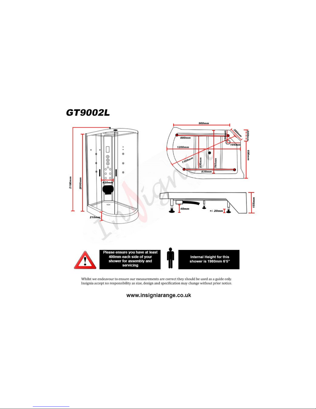
GT9002L
ATTENTION INSTALLERS:
These instrucons must be
le with the customer
30 Day Technical Support: 01908 226545
(NOTE: This service is only available to customers from the day of deli very,
please have your supplier’s details and your postcode to hand be fore calling)
Replacements Parts: inside of your warranty contact:
www.insigniarange.co.uk/customerService.aspx
Spares/Replacements Parts: outside of your warranty
contact 0844 800 3069
www.insigniarange.co.uk
WARRANTY REG NO: __________________________
To claim your full 5 year warranty, register your shower within 90 days of delivery at: www.insigniarange.co.uk/
warrantyreg.aspx. Standard 12 month warranty applies if outside this me period.
CHECK ALL CONTENTS BEFORE BUILD COMMENCES. NO RETURNS CAN BE MADE
ONCE THE BUILD HAS STARTED AS IT IS DEEMED ACCEPTANCE OF PRODUCT!
Page 2

www.insigniarange.com Last Modied: 26/01/2017
02
Contents
Introduction
Electrical Requirements
What’s In The Boxes?
Screw Pack Contents
Plumbing Requirements
Schematics
Starting The Installation
Electric Box Connections
Sealing and Water Testing
MK117L Control Panel Instructions
Help Book Information
Parts list
3
5
6
8
9
10
11
20
21
22
23
24
Page 3
www.insigniarange.com Last Modied: 26/01/2017
03
Thank you for your recent purchase of an Insignia shower. Please read this booklet with great care to ensure you get the best out of your build and have a shower that
will last for many years to come!
Like everything, in order to obtain a first class product that will serve you well for many years, the effort and correctness put into the assembly will reflect in the quality of
your finish.
OUR BADGE RATING IN TERMS OF DIFFICULTY OF ASSEMBLY IS BASED ON CLIENT FEEDBACK
1 Badge = Very easy
2 Badges = Easy
3 Badges = Moderate
4 Badges = Harder than average
5 Badges = Professional skills required
This shower is rated 3 Badges
Page 4

www.insigniarange.com Last Modied: 26/01/2017
04
ASSEMBLY AND PLUMBING
THIS PRODUCT BUILD IS RATED SUITABLE FOR DIY PURPOSES PROVIDING THE CUSTOMER IS OF ABOVE AVERAGE SKILL AND FEELS CONFIDENT IN
THEIR ABILITY. ONLY YOU THE CUSTOMER WILL KNOW THIS SO BEFORE ANY ATTEMPT IS MADE TO ASSEMBLE, READ THROUGH THE FOLLOWING
PAGES IN DETAIL THEN DECIDE. IF YOU HAVE ANY DOUBT USE THE SERVICES OF A PROFESSIONAL. IN PICKING SUCH, ALLOW THEM TO DECIDE IF
THEY ARE CAPABLE OF BUILD BY FIRST SHOWING THESE INSTRUCTIONS TO THEM. ALWAYS GET THREE QUOTES.
REMEMBER THE BEST IS NOT ALWAYS THE CHEAPEST!
REMEMBER PLUMBERS PLUMB! 90% OF THIS JOB IS NOT PLUMBING!
DUE TO THE NATURE OF THIS PRODUCT WE HIGHLY ADVISE THE PURCHASE AND FITTING OF A WATER SOFTENER
(PLEASE NOTE LIMESCALE BUILD UP MAY CAUSE DAMAGE TO YOUR SHOWER AND WILL NOT BE COVERED UNDER WARRANTY)
ELECTRICAL CONNECTION TO HOUSE MAINS
WHEN YOUR ITEM IS ASSEMBLED ALWAYS USE THE SERVICES OF A FULLY QUALIFIED ELECTRICAN COMPANY TO COMPLETE THE CONNECTION FROM
SHOWER TO THE HOUSE SUPPLY. LAWS DEMAND IN MANY CASES YOU DO THIS AND YOUR WARRANTY IS VOID IN REGARDS TO THE ELECTRICAL
ITEMS IF THIS IS NOT UNDERTAKEN.
YOURS AND OTHERS SAFETY IS PARAMOUNT. NEVER ATTEMPT THIS YOURSELF!
REMEMBER:
These showers are designed to be free standing and movable from their location should you have the need to replace anything. ALWAYS USE Flexible braided water
inlet pipes (not supplied) at least a metre long (not central heating plastic type!)
Always use a flexible waste pipe from your house supply to the shower .
NEVER FIX with rigid pipes, NEVER FIX the unit to the wall.
DURING BUILD, LIKE ALL SHOWERS CORRECT SEALING IS IMPERATIVE.
If you are using Insignia’s RubberGum, please ensure the product does not come in contact with your silicone as this will cause the RubberGum to fail and
will not adhere as intended.
ATTENTION
ALWAYS FIT EASY TO GET TO ISOLATION TAPS ON BOTH THE HOT AND COLD WATER SUPPLY (NOT SUPPLIED). JUST LIKE A
DISHWASHER OR WASHING MACHINE, THIS PRODUCT MUST BE ISOLATED WHEN NOT IN USE.
FLEXIBLE SUPPLY HOSES (NOT SUPPLIED) COUPLE HERE AS ORIGIN OF SUPPLY
Page 5

www.insigniarange.com Last Modied: 26/01/2017
05
TOTAL ELECTRICAL REQUIREMENTS
Voltage Rating 220 -240AC
Frequency Rating 50HZ
Power Rating 2.8KW
Your electrical contractor should understand ALL legal requirements of connection before undertaking any work or installation.
UNDER NO CIRCUMSTANCES UNDERTAKE THIS YOURSELF!!!
Note for electrician. This product comes with 13 amp plug(s) fitted with an RCD unit. We leave it this way for you to connect this your own way
due to continued additions to current regulations. As at October 2010 we offered two methods.
1) Connect within current laws and IP directives using plug and RCD provided with steam version or supply one for non steam version
2) (Preferred) Wire into isolated fused feed connecting directly to the house consumer/service box. Remove the fitted plug and ensure the
Consumer unit has capabilities to replace RCD feature if RCD is removed.
Always use protection against electrical surge. Your shower should be treated the same as a home computer. A surge protector should
eradicate the possibility of either the transformer or computer control being burnt out. Please note earth is required and found on chassis of
shower tray. A further earth is required from Steam Generator unit. Each earth must ground through power supply line.
Page 6
www.insigniarange.com Last Modied: 26/01/2017
06
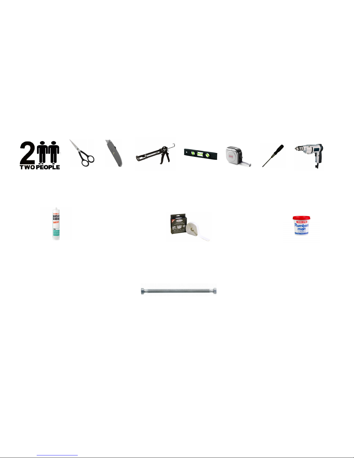
Tool Requirements
None Supplied
Scissors Stanley Blade Silicone Gun Spirit Level Tape Measure Philips Screwdriver Electric Drill
Adhesive Requirements
Hardware Requirements
Bacteria Resistant Sanitary Silicone - (for vertical joints) RubberGum Plumbers Mait (for waste joints)
A Hydro-Massage Shower requires 2 x 1 Metre Braided Hose
Not Supplied
Not Supplied
Not Supplied
Supplied
Page 7

www.insigniarange.com Last Modied: 26/01/2017
07
Whilst the next steps show you how to assemble your shower we want to make sure you have a correct build to ensure you get a trouble free shower. Therefore our advice
is to follow the instructions and perform a dry run to ensure you are confident with the build and you understand fully how t he unit is assembled. When we use the word
“DRY RUN” this means you do not silicone anything, just simply construct the shower, align, drill and screw everything together. Once y ou are happy with the build take the
unit apart and carry out the final fix.
What’s In The Boxes?
Tray Box
1x Tray
1x Roof
2x Curved Rails
1 x AC-DC 12V Adapter
Glass Room
2x Door seals
2x Glass doors
2x fixed glass
Column
1x Complete Column
Backwalls
1x Left Panel Backwall
1x Right Panel Backwall
In addition to above you will have all the required internal accessories to complete the shower
Page 8

www.insigniarange.com Last Modied: 26/01/2017
08
Insignia Screw Pack
VERY IMPORTANT
Have you got everything? If not please contact the Insignia Support Line on 01908 226545. Remember NEVER book your tradesman until everything has arrived, been
checked and is present. No replacement/missing parts can be obtained free of charge during or after the build. Any claims can only be within the timescale permitted (48
hours after delivery) and always BEFORE build.
Product Code Descripon Quanty
SP097 Door Handles 2
SP008 Door Wheels 8
ST20 20mm Screws 20
ST35 35mm Screws 10
ST14 14mm Screws 6
ST25 25mm Screws 10
SW9 Small Washers 20
DB9 Drill Piece 1
Note: In some cases you may have more screws than needed, this is done so you have spares!
Page 9

www.insigniarange.com Last Modied: 26/01/2017
09
Pressure Requirements from your house supply
We recommend a bar pressure between 2.5 and 3.4 BAR. If you have a combi boiler system no problem should be experienced. If you have a gravity feed older type
installation (hot water tank type usually less than 1 bar) you will almost certainly need a pump. We cannot advise on which t ype of pump is used, location or design because
all house plumbing layouts vary. This is a job for your installer/plumber. The end delivery however must fall within the scop e above.
Important Note Do n ot exceed 3.4 BAR pressu re u nder any ci rcumstan ces. War ran ty is voi d i f s o as d amag e will o cc ur. If you h ave a c ombi s up ply, pl ease u se a
pressure reducing valve if required to lower the BAR pressure to the shower.
Please Remember that this product is free standing and is designed to be pulled away from the wall.
The waste hose must be of a flexible type (1m flexible waste supplied).
The water supply pipes need to be at least 1 metre in length and must be that of a flexible braided type (not supplied).
DO NOT OVERTIGHTEN THE BRAIDED HOSES AS IT CAN CAUSE THE CONNECTION TO POP AFTER A FEW WEEKS OF USE
Page 10
www.insigniarange.com Last Modied: 26/01/2017
10
Page 11
www.insigniarange.com Last Modied: 26/01/2017
11
TO START
Make sure you have a clear space, remember when finished and in place you need access to check your
build and able to pull the shower out for servicing or should you have the need to replace anything!
Take the shower tub and remove all the protective wrapping and fit the waste. In the side of the waste
supplied in the optional fitting kit you will notice a spigot not seen on an ordinary waste. In most cases this
is blanked yet should you have a steam version you need to gently drill this out as this item is for the
steam generator drainage and will be connected in the instructions later.
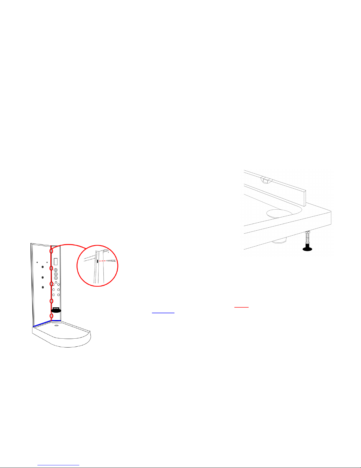
Step 1
Attach the small hand back panel to the back column.
Once you are happy with the alignment, run a bead of silicone up the
edge and Rubbergum along the bottom of the panels and screw to-
gether using the ST20
(please note, if your column has a rubber seal at the bottom , take the rubber
off and apply silicone inside the rubber and replace)
Whilst the next steps show you how to assemble your shower we want to make sure you have a correct build to ensure you get a
trouble free shower. Therefore our advice is to follow the instructions and perform a dry run to ensure you are confident with the
build and you understand fully how the unit is assembled. When we use the word “DRY RUN” this means you do not silicone
anything, just simply construct the shower, align, drill and screw everything together. Once you are happy with the build take the unit
apart and carry out the final fix.
Page 12
www.insigniarange.com Last Modied: 26/01/2017
12
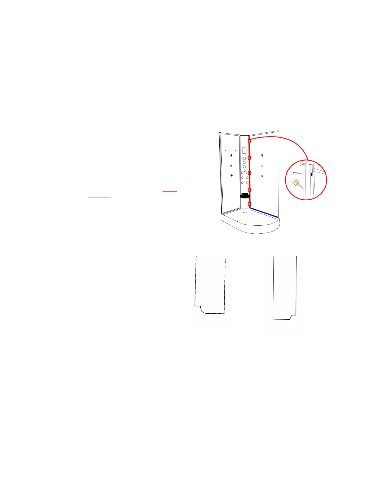
Step 2
Now attach the large back panel to the column.
Once you are happy with the alignment, run a bead of silicone up
the edge and Rubbergum along the bottom of the panels and
screw together using the ST20
Step 3
Front Fixed Uprights.
PLEASE NOTE:
The uprights have small grooves cut out, please see diagram. These
are designed to go at the bottom, connecting to the tray.
Please see next page for positioning on the tray!
Page 13
www.insigniarange.com Last Modied: 26/01/2017
13
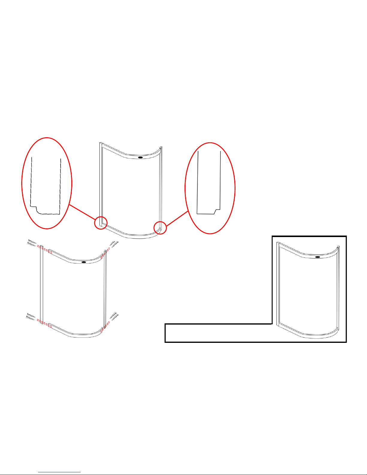
Step 3 (Continued)
The next step is to attach both front uprights to the curved rails using
the ST35 screws as shown in the picture to the left
PLEASE NOTE
The screw head needs to bypass the OUTER hole. If this does not
occur please bore out the outer hole only by about 2-4mm
Your front metal work should now look like this
Step 3 (Continued)
Please Note:
With the groove sitting on the tray, you need to
have the “U” shaped channel facing inwards to
allow the glass to be inserted correctly.
Page 14
www.insigniarange.com Last Modied: 26/01/2017
14
Step 5
Next attach the “U shape” rubber glass seal to the outer edge of the
curved and the straight fixed glass panels and cut any excess of if
required.
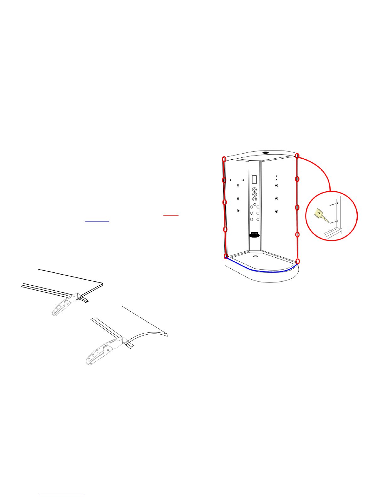
Step 4
Now attach your front metal work to the fitted back panels.
Once you are happy with the alignment, run a bead of silicone up
the edge and Rubbergum along the bottom of the panels and
frame and screw together using the ST20
Page 15
www.insigniarange.com Last Modied: 26/01/2017
15
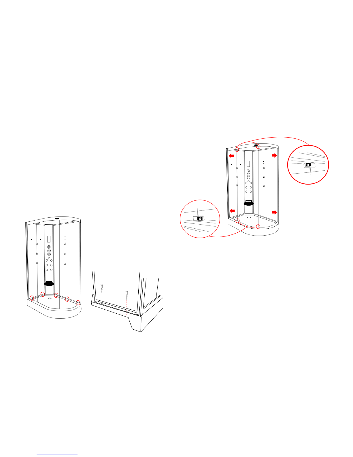
Step 7
Using the ST25 screws, ensure the back panels are square and you are happy with the
position of the panels then screw into place
Step 6
With the frame now attached to the back panels, locate and fix the glass panels into
place by pushing them as per the arrows in the adjacent image Making sure the
edge of the glass with the rubber seal fits into the grove tightly. Now screw the glass
retaining clips into place using the ST14 screws making sure the glass has a tight fit
Page 16

www.insigniarange.com Last Modied: 26/01/2017
16
Step 8
Next locate the roof into position. Once you are happy with the positioning of
this, screw into place using the ST25 screws,
Step 9
Fit the adjustable wheels to the top and bottom of the glass doors and ensure the
wheels are at their lowest position and hang on the inner curved rails with the wheels
facing the outside of the glass.
Once all wheels are fitted and on the rails you can adjust the wheels by turning the
plastic bolt clockwise in which in turn will pull the wheels towards the track ensuring a
secure a tight fit.
Now grease the track to ensure a smooth and long lasting operation
(not supplied)
Page 17

www.insigniarange.com Last Modied: 26/01/2017
17
Shelf
Fix the chrome floating shelf brackets to your glass back panel by using the provided screws. Now attach the chrome tubed bar s to your glass shelf as illustrated in the
below image. Next slide the shelf into your shelf brackets and secure by tightening the grub screw situated on the bottom of the bracket.
Accessory Installation
Please Note
Ensure all grey backing film on the rear of the glass panels are pierced through the existing glass holes
with a knife to provide an efficient smooth fitting and location of the accessories. We recommend using
a screwdriver on the smaller holes.
Hand Shower
1. Attach the chrome holder to the
back wall via the 2 screws provided
in the pack.
2. Attach the chrome water outlet to
the back of the centre column, fixing
it from the rear with the plastic hex
nut.
3. Attach the chrome flexible hose to
the water outlet with via small cou-
pling end
4. Attach the other end (sleeved) to
the hand shower and place in to the
holder.
NOTE: If you attach the wrong end of the
hose to the hand shower it will not sit in
the holder.
Page 18

www.insigniarange.com Last Modied: 26/01/2017
18
Door Seals
Magnetic Seal: Push the magnetic door seal on the handle side of the glass door ensuring
this is tightly fitted.
Rear Door Seal: Place the rear door seal on the opposite side to the magnetic strip ensuring
the flap is facing the fixed glass panel
Handle
Ensuring that the inner thread is protruding out from the handle far enough, place the handle
on the outside of the door and secure by tightening the inner chrome knob to the protruding
inner thread.
Monsoon Head
Attach the grey hose from your valve to the inner black tube using PTFE tape
(please note this only needs to be hand tight. Over tightening will snap/damage
the inner black tube)
Page 19

www.insigniarange.com Last Modied: 26/01/2017
19
Hot Water Inlet Cold Water Inlet
Hand Shower
Body Jets
Side Body Jets Monsoon Shower
Shower Valve
Connect the corresponding hoses to the rear of the valve as shown.
Device output may differ from the image. Please refer to your outer chrome faceplate in-
side your Insignia shower as a reference point.
IF YOUR DIAL DOES NOT CORRESPOND TO THE APPROPRIATE DEVICE:
Turn on your water to the shower and note which output the water exits from then turn off
the water and swap over the relevant hose.
Alternatively remove the outer chrome knob by removing the chrome cap and loosening
the grub screw (please ensure not to unscrew fully as this will drop within the chrome
knob) this is found on the opposite side to the chrome pillar. Once you have succeeded in
loosening this you can now slide your faceplate to correspond to the device.
This should be capped with a
brass cap.
Page 20

www.insigniarange.com Last Modied: 26/01/2017
20
Electric Box Connections
Roof Light
Fan
Speaker
Antenna
Back Lights
RJ11 Phone Connection
12V power Supply
Connect the cables below to the corresponding devices on the shower
Page 21

www.insigniarange.com Last Modied: 26/01/2017
21
Silicone Seal (vertical joints) - RubberGum (horizontal joints)
TESTING FOR WATER LEAKS
LEAVE THE SHOWER 24 HOURS AFTER BUILD TO ALLOW SEALENT TO
CURE AND ENSURE THE SHOWER IS AWAY FROM ITS FINAL POSITION
TO ALLOW REAR VIEWING
Ensure all connections are tight and sealed including the waste, body jets and
steam outlet (model dependent) on your shower.
Switch on the overhead shower NOT the massage jets, remember these will fire
water out at you and are not suitable for checking leaks as they would normally
only operate when a person is in front of them. DO NOT AIM THE HAND
SHOWER AT THE JOINTS OF YOUR SHOWER AS THIS DOES NOT FALL
UNDER “NORMAL EVERYDAY USE”. Adjust the feet to ensure the direction of
the water flows towards to the waste to prevent puddling.
Just use COLD water setting as hot will make cabin misty and condensate thus
the inspection becomes very difficult. Now on the OUTSIDE of the shower
inspect each joint, factory seal, hose, clip and jet by walking from one side and
going around to the back and then to the other side finishing at the front. If you
have a small leak (normally caused through insufficient sealer or air bubble on
assembly, dry the area thoroughly and reseal.
Please remember the location of the water may not be exactly where the leak is
as it could have run around to a low point. Never seal your inner fittings unless
necessary, remember you will see this for the life of the shower! Again leave to
cure and check. Once you are happy check the shower functions i.e. jets for
back massage, foot massage and finally hand shower (model dependent) check
your joints to these functions at the rear again. Never use the shower until all
checks have been made and the installer is 100% happy in the knowledge no
leaks are present.
All good?
Now push your shower FROM THE BASE and NEVER THE GLASS OR FRAME
into its final resting position.
Happy Showering!
Page 22

www.insigniarange.com Last Modied: 26/01/2017
22
MK117L Control Panel Instructions
Buon 1 (Light Bulb)
Press 1x For Top Light
Press 2x For Column Light
Press 3x For All Lights
Press 4x To Switch O Lights
Buon 2 (Radio)
On/O
Buon 3 (Fan)
On/O
Buon 4 (Speaker)
Volume Down
Buon 5 (Radio)
Press once to acvate manual tune
Press and hold to acvate auto scan
Buon 6 (Speaker)
Volume Up
Buon 7 (Down Arrow)
Channel select down/manual search down
Buon 8 (M)
Access saved channels
Buon 9 (Up Arrow)
Channel select up/manual search up
Buon 10 (Alarm)
Acvate Alarm
Buon 11 (Telephone)
Answer telephone
Buon 12 (Lock)
The control panel will automacally lock when not in use for a
short me, hold this buon down for 3 seconds unl a beep is
heard and this will unlock and reacvate the control panel for
use
PLEASE NOTE:
(when in lock mode the display will have 2 ashing lines on the
display and the only buon that will work is the alarm)
Page 23

www.insigniarange.com Last Modied: 26/01/2017
23
Need Help?
Then simply download the following "Help" advice booklet found at this link below. This contains many useful items such as is your parts warranty registered, advice on
cleaning / servicing your shower cabin, fault finding and many more items. This is a MUST to read and not just "HELP". It saves time in nearly all cases, avoiding contact
with ourselves as most answers are there for a ready fix!
Simply visit: www.insigniarange.co.uk/help.aspx
Page 24

www.insigniarange.com Last Modied: 26/01/2017
24
Internal Items
External Items
Parts List
Part Code Part Descripon
GT9002L-15 Le Upright (straight)
GT9002L-16 Right Upright (Angled)
GT9002L-9 Blank column
GT9002L-17 Top rail
GT9002L-18 Boom rail
GT9002L-3 Blank roof
GT9002L-19 Tray
Framework (Le hand)
Part Code Part Descripon
GT9002L-6 Curved front door
GT9002L-7 Flat front glass door
GT9002L-14
GT9002L-11
Large Black Backwall
Small Black Backwall
GT9002L-12
GT9002L-4
Large Mirrored Backwall
Small Mirrored Backwall
GT9002L-13
GT9002L-10
Large White Backwall
Small White Backwall
GT9002L-5 Curved front xed glass
GT9002L-8 Flat front xed glass
Glass (Le Hand)
Part Code Part Descripon
SP063 Monsoon Shower head
SP243 Fold down seat
SP048 Massage jet—2 open ends
SP048A Massage jet—1 open, 1 closed
SP123 Shower head holder
SP159 Shower waste
SP097 Chrome rectangular door han-
dles
SP240 Glass Shelf
SP072 Door stoppers
SP008 Door Wheels
SP060 Electrical extension cable
SP003 Ring light
SP038 Speaker
SP007 Fan
SP037 Fan & speaker cover
SP177 MK117L Control panel
SP152 Standard shower head
Sp166 Approximately 4 meters of
“U Style” seals
Part Code Part Descripon
SP300 Waste hose
SP187 Drain Hose
SP024 Transformer
SP308 Magnec door seals
SP310 Rear door seals
SP153
SP126
SP045
SP182
SP043
3 port—3 feed thermostac valve
4 Port Selector Cartridge
On/O Water Mixer
Valve
Vernet Screw Fit Thermostac Cartridge
Plasc Thermostac
Page 25

www.insigniarange.com Last Modied: 26/01/2017
25
All images are subject to copyright. Images may not be used in any way shape or form with out written permission from Maclean International Ltd. Images are NOT permitted
to be saved, printed or uploaded. Violation of copyright laws are punishable by law.
All images are registered with
ImageTraker
Insignia™ is a registered trademark of Maclean International Ltd
Page 26

www.insigniarange.com Last Modied: 26/01/2017
INSTALLATION MANUAL
GT9002R
ATTENTION INSTALLERS:
These instrucons must be
le with the customer
30 Day Technical Support: 01908 226545
(NOTE: This service is only available to customers from the day of deli very,
please have your supplier’s details and your postcode to hand be fore calling)
Replacements Parts: inside of your warranty contact:
www.insigniarange.co.uk/customerService.aspx
Spares/Replacements Parts: outside of your warranty
contact 0844 800 3069
www.insigniarange.co.uk
WARRANTY REG NO: __________________________
To claim your full 5 year warranty, register your shower within 90 days of delivery at: www.insigniarange.co.uk/
warrantyreg.aspx. Standard 12 month warranty applies if outside this me period.
CHECK ALL CONTENTS BEFORE BUILD COMMENCES. NO RETURNS CAN BE MADE
ONCE THE BUILD HAS STARTED AS IT IS DEEMED ACCEPTANCE OF PRODUCT!
Page 27

www.insigniarange.com Last Modied: 26/01/2017
02
Contents
Introduction
Electrical Requirements
What’s In The Boxes?
Screw Pack Contents
Plumbing Requirements
Schematics
Starting The Installation
Electric Box Connections
Sealing and Water Testing
MK117L Control Panel Instructions
Help Book Information
Parts list
3
5
7
8
9
10
11
20
21
22
23
24
Page 28

www.insigniarange.com Last Modied: 26/01/2017
03
Thank you for your recent purchase of an Insignia shower. Please read this booklet with great care to ensure you get the best out of your build and have a shower that
will last for many years to come!
Like everything, in order to obtain a first class product that will serve you well for many years, the effort and correctness put into the assembly will reflect in the quality of
your finish.
OUR BADGE RATING IN TERMS OF DIFFICULTY OF ASSEMBLY IS BASED ON CLIENT FEEDBACK
1 Badge = Very easy
2 Badges = Easy
3 Badges = Moderate
4 Badges = Harder than average
5 Badges = Professional skills required
This shower is rated 3 Badges
Page 29

www.insigniarange.com Last Modied: 26/01/2017
04
ASSEMBLY AND PLUMBING
THIS PRODUCT BUILD IS RATED SUITABLE FOR DIY PURPOSES PROVIDING THE CUSTOMER IS OF ABOVE AVERAGE SKILL AND FEELS CONFIDENT IN
THEIR ABILITY. ONLY YOU THE CUSTOMER WILL KNOW THIS SO BEFORE ANY ATTEMPT IS MADE TO ASSEMBLE, READ THROUGH THE FOLLOWING
PAGES IN DETAIL THEN DECIDE. IF YOU HAVE ANY DOUBT USE THE SERVICES OF A PROFESSIONAL. IN PICKING SUCH, ALLOW THEM TO DECIDE IF
THEY ARE CAPABLE OF BUILD BY FIRST SHOWING THESE INSTRUCTIONS TO THEM. ALWAYS GET THREE QUOTES.
REMEMBER THE BEST IS NOT ALWAYS THE CHEAPEST!
REMEMBER PLUMBERS PLUMB! 90% OF THIS JOB IS NOT PLUMBING!
DUE TO THE NATURE OF THIS PRODUCT WE HIGHLY ADVISE THE PURCHASE AND FITTING OF A WATER SOFTENER
(PLEASE NOTE LIMESCALE BUILD UP MAY CAUSE DAMAGE TO YOUR SHOWER AND WILL NOT BE COVERED UNDER WARRANTY)
ELECTRICAL CONNECTION TO HOUSE MAINS
WHEN YOUR ITEM IS ASSEMBLED ALWAYS USE THE SERVICES OF A FULLY QUALIFIED ELECTRICAN COMPANY TO COMPLETE THE CONNECTION FROM
SHOWER TO THE HOUSE SUPPLY. LAWS DEMAND IN MANY CASES YOU DO THIS AND YOUR WARRANTY IS VOID IN REGARDS TO THE ELECTRICAL
ITEMS IF THIS IS NOT UNDERTAKEN.
YOURS AND OTHERS SAFETY IS PARAMOUNT. NEVER ATTEMPT THIS YOURSELF!
REMEMBER:
These showers are designed to be free standing and movable from their location should you have the need to replace anything. ALWAYS USE Flexible braided water
inlet pipes (not supplied) at least a metre long (not central heating plastic type!)
Always use a flexible waste pipe from your house supply to the shower .
NEVER FIX with rigid pipes, NEVER FIX the unit to the wall.
DURING BUILD, LIKE ALL SHOWERS CORRECT SEALING IS IMPERATIVE.
If you are using Insignia’s RubberGum, please ensure the product does not come in contact with your silicone as this will cause the RubberGum to fail and
will not adhere as intended.
ATTENTION
ALWAYS FIT EASY TO GET TO ISOLATION TAPS ON BOTH THE HOT AND COLD WATER SUPPLY (NOT SUPPLIED). JUST LIKE A
DISHWASHER OR WASHING MACHINE, THIS PRODUCT MUST BE ISOLATED WHEN NOT IN USE.
FLEXIBLE SUPPLY HOSES (NOT SUPPLIED) COUPLE HERE AS ORIGIN OF SUPPLY
Page 30

www.insigniarange.com Last Modied: 26/01/2017
05
TOTAL ELECTRICAL REQUIREMENTS
Voltage Rating 220 -240AC
Frequency Rating 50HZ
Power Rating 2.8KW
Your electrical contractor should understand ALL legal requirements of connection before undertaking any work or installation.
UNDER NO CIRCUMSTANCES UNDERTAKE THIS YOURSELF!!!
Note for electrician. This product comes with 13 amp plug(s) fitted with an RCD unit. We leave it this way for you to connect this your own way
due to continued additions to current regulations. As at October 2010 we offered two methods.
1) Connect within current laws and IP directives using plug and RCD provided with steam version or supply one for non steam version
2) (Preferred) Wire into isolated fused feed connecting directly to the house consumer/service box. Remove the fitted plug and ensure the
Consumer unit has capabilities to replace RCD feature if RCD is removed.
Always use protection against electrical surge. Your shower should be treated the same as a home computer. A surge protector should
eradicate the possibility of either the transformer or computer control being burnt out. Please note earth is required and found on chassis of
shower tray. A further earth is required from Steam Generator unit. Each earth must ground through power supply line.
Page 31

www.insigniarange.com Last Modied: 26/01/2017
06
Tool Requirements
None Supplied
Scissors Stanley Blade Silicone Gun Spirit Level Tape Measure Philips Screwdriver Electric Drill
Adhesive Requirements
Hardware Requirements
Bacteria Resistant Sanitary Silicone - (for vertical joints) RubberGum Plumbers Mait (for waste joints)
A Hydro-Massage Shower requires 2 x 1 Metre Braided Hose
Not Supplied
Not Supplied
Not Supplied
Supplied
Page 32

www.insigniarange.com Last Modied: 26/01/2017
07
Whilst the next steps show you how to assemble your shower we want to make sure you have a correct build to ensure you get a trouble free shower. Therefore our advice
is to follow the instructions and perform a dry run to ensure you are confident with the build and you understand fully how t he unit is assembled. When we use the word
“DRY RUN” this means you do not silicone anything, just simply construct the shower, align, drill and screw everything together. Once y ou are happy with the build take the
unit apart and carry out the final fix.
What’s In The Boxes?
Tray Box
1x Tray
1x Roof
2x Curved Rails
1 x AC-DC 12V Adapter
Glass Room
2x Door seals
2x Glass doors
2x fixed glass
Column
1x Complete Column
Backwalls
1x Left Panel Backwall
1x Right Panel Backwall
In addition to above you will have all the required internal accessories to complete the shower
Page 33

www.insigniarange.com Last Modied: 26/01/2017
08
Insignia Screw Pack
VERY IMPORTANT
Have you got everything? If not please contact the Insignia Support Line on 01908 226545. Remember NEVER book your tradesman until everything has arrived, been
checked and is present. No replacement/missing parts can be obtained free of charge during or after the build. Any claims can only be within the timescale permitted (48
hours after delivery) and always BEFORE build.
Product Code Descripon Quanty
SP097 Door Handles 2
SP008 Door Wheels 8
ST20 20mm Screws 20
ST35 35mm Screws 10
ST14 14mm Screws 6
ST25 25mm Screws 10
SW9 Small Washers 20
DB9 Drill Piece 1
Note: In some cases you may have more screws than needed, this is done so you have spares!
Page 34

www.insigniarange.com Last Modied: 26/01/2017
09
Pressure Requirements from your house supply
We recommend a bar pressure between 2.5 and 3.4 BAR. If you have a combi boiler system no problem should be experienced. If you have a gravity feed older type
installation (hot water tank type usually less than 1 bar) you will almost certainly need a pump. We cannot advise on which t ype of pump is used, location or design because
all house plumbing layouts vary. This is a job for your installer/plumber. The end delivery however must fall within the scop e above.
Important Note Do n ot exceed 3.4 BAR pressu re u nder any ci rcumstan ces. War ran ty is voi d i f s o as d amag e will o cc ur. If you h ave a c ombi s up ply, pl ease u se a
pressure reducing valve if required to lower the BAR pressure to the shower.
Please Remember that this product is free standing and is designed to be pulled away from the wall.
The waste hose must be of a flexible type (1m flexible waste supplied).
The water supply pipes need to be at least 1 metre in length and must be that of a flexible braided type (not supplied).
DO NOT OVERTIGHTEN THE BRAIDED HOSES AS IT CAN CAUSE THE CONNECTION TO POP AFTER A FEW WEEKS OF USE
Page 35

www.insigniarange.com Last Modied: 26/01/2017
10
Page 36

www.insigniarange.com Last Modied: 26/01/2017
11
Step 1
Attach the small hand back panel to the back column.
Once you are happy with the alignment, run a bead of silicone up the
edge and Rubbergum along the bottom of the panels and screw
together using the ST20
(please note, if your column has a rubber seal at the bottom , take the rubber
off and apply silicone inside the rubber and replace)
Whilst the next steps show you how to assemble your shower we want to make sure you have a correct build to ensure you get a
trouble free shower. Therefore our advice is to follow the instructions and perform a dry run to ensure you are confident with the
build and you understand fully how the unit is assembled. When we use the word “DRY RUN” this means you do not silicone
anything, just simply construct the shower, align, drill and screw everything together. Once you are happy with the build take the unit
apart and carry out the final fix.
TO START
Make sure you have a clear space, remember when finished and in place you need access to check your
build and able to pull the shower out for servicing or should you have the need to replace anything!
Take the shower tub and remove all the protective wrapping and fit the waste. In the side of the waste
supplied in the optional fitting kit you will notice a spigot not seen on an ordinary waste. In most cases this
is blanked yet should you have a steam version you need to gently drill this out as this item is for the
steam generator drainage and will be connected in the instructions later.
Now please level the tray by firstly placing the tray in its final location and then using a spirit level, adjust
the tray feet accordingly. Once you are happy with the levelling of the tray, you can pull it out to begin the
main construction.
Page 37

www.insigniarange.com Last Modied: 26/01/2017
12
Step 2
Now attach the large back panel to the column.
Once you are happy with the alignment, run a bead of silicone up
the edge and Rubbergum along the bottom of the panels and
screw together using the ST20
Step 3
Front Fixed Uprights.
PLEASE NOTE:
The uprights have small grooves cut out, please see diagram. These
are designed to go at the bottom, connecting to the tray.
Please see next page for positioning on the tray!
Page 38

www.insigniarange.com Last Modied: 26/01/2017
13
Step 3
The next step is to attach both front uprights to the curved rails using
the ST35 screws as shown in the picture to the left
PLEASE NOTE
The screw head needs to bypass the OUTER hole. If this does not
occur please bore out the outer hole only by about 2-4mm
Your front metal work should now look like this
Step 3 (Continued)
Please Note:
With the groove sitting on the tray, you need to
have the “U” shaped channel facing inwards to
allow the glass to be inserted correctly.
Page 39

www.insigniarange.com Last Modied: 26/01/2017
14
Step 5
Next attach the “U shape” rubber glass seal to the outer edge of the
curved and the straight fixed glass panels and cut any excess of if
required.
Step 4
Now attach your front metal work to the fitted back panels.
Once you are happy with the alignment, run a bead of silicone up
the edge and Rubbergum along the bottom of the panels and
frame and screw together using the ST20
Page 40

www.insigniarange.com Last Modied: 26/01/2017
15
Step 7
Using the ST25 screws, ensure the back panels are square and you are happy with the
position of the panels then screw into place
Step 6
With the frame now attached to the back panels, locate and fix the glass panels into
place by pushing them as per the arrows in the adjacent image Making sure the
edge of the glass with the rubber seal fits into the grove tightly. Now screw the glass
retaining clips into place using the ST14 screws making sure the glass has a tight fit
Page 41

www.insigniarange.com Last Modied: 26/01/2017
16
Step 8
Next locate the roof into position. Once you are happy with the positioning of
this, screw into place using the ST25 screws,
Step 9
Fit the adjustable wheels to the top and bottom of the glass doors and ensure the
wheels are at their lowest position and hang on the inner curved rails with the wheels
facing the outside of the glass.
Once all wheels are fitted and on the rails you can adjust the wheels by turning the
plastic bolt clockwise in which in turn will pull the wheels towards the track ensuring a
secure a tight fit.
Now grease the track to ensure a smooth and long lasting operation
(not supplied)
Page 42

www.insigniarange.com Last Modied: 26/01/2017
17
Shelf
Fix the chrome floating shelf brackets to your glass back panel by using the provided screws. Now attach the chrome tubed bar s to your glass shelf as illustrated in the
below image. Next slide the shelf into your shelf brackets and secure by tightening the grub screw situated on the bottom of the bracket.
Accessory Installation
Please Note
Ensure all grey backing film on the rear of the glass panels are pierced through the existing glass holes
with a knife to provide an efficient smooth fitting and location of the accessories. We recommend using
a screwdriver on the smaller holes.
Hand Shower
1. Attach the chrome holder to the
back wall via the 2 screws provided
in the pack.
2. Attach the chrome water outlet to
the back of the centre column, fixing
it from the rear with the plastic hex
nut.
3. Attach the chrome flexible hose to
the water outlet with via small cou-
pling end
4. Attach the other end (sleeved) to
the hand shower and place in to the
holder.
NOTE: If you attach the wrong end of the
hose to the hand shower it will not sit in
the holder.
Page 43

www.insigniarange.com Last Modied: 26/01/2017
18
Door Seals
Magnetic Seal: Push the magnetic door seal on the handle side of the glass door ensuring
this is tightly fitted.
Rear Door Seal: Place the rear door seal on the opposite side to the magnetic strip ensuring
the flap is facing the fixed glass panel
Handle
Ensuring that the inner thread is protruding out from the handle far enough, place the handle
on the outside of the door and secure by tightening the inner chrome knob to the protruding
inner thread.
Monsoon Head
Attach the grey hose from your valve to the inner black tube using PTFE tape
(please note this only needs to be hand tight. Over tightening will snap/damage
the inner black tube)
Page 44

www.insigniarange.com Last Modied: 26/01/2017
19
Hot Water Inlet Cold Water Inlet
Hand Shower
Body Jets
Side Body Jets Monsoon Shower
Shower Valve
Connect the corresponding hoses to the rear of the valve as shown.
Device output may differ from the image. Please refer to your outer chrome faceplate in-
side your Insignia shower as a reference point.
IF YOUR DIAL DOES NOT CORRESPOND TO THE APPROPRIATE DEVICE:
Turn on your water to the shower and note which output the water exits from then turn off
the water and swap over the relevant hose.
Alternatively remove the outer chrome knob by removing the chrome cap and loosening
the grub screw (please ensure not to unscrew fully as this will drop within the chrome
knob) this is found on the opposite side to the chrome pillar. Once you have succeeded in
loosening this you can now slide your faceplate to correspond to the device.
This should be capped with a
brass cap.
Page 45

www.insigniarange.com Last Modied: 26/01/2017
20
Electric Box Connections
Roof Light
Fan
Speaker
Antenna
Back Lights
RJ11 Phone Connection
12V power Supply
Connect the cables below to the corresponding devices on the shower
Page 46

www.insigniarange.com Last Modied: 26/01/2017
21
Silicone Seal (vertical joints) - RubberGum (horizontal joints)
TESTING FOR WATER LEAKS
LEAVE THE SHOWER 24 HOURS AFTER BUILD TO ALLOW SEALENT TO
CURE AND ENSURE THE SHOWER IS AWAY FROM ITS FINAL POSITION
TO ALLOW REAR VIEWING
Ensure all connections are tight and sealed including the waste, body jets and
steam outlet (model dependent) on your shower.
Switch on the overhead shower NOT the massage jets, remember these will fire
water out at you and are not suitable for checking leaks as they would normally
only operate when a person is in front of them. DO NOT AIM THE HAND
SHOWER AT THE JOINTS OF YOUR SHOWER AS THIS DOES NOT FALL
UNDER “NORMAL EVERYDAY USE”. Adjust the feet to ensure the direction of
the water flows towards to the waste to prevent puddling.
Just use COLD water setting as hot will make cabin misty and condensate thus
the inspection becomes very difficult. Now on the OUTSIDE of the shower
inspect each joint, factory seal, hose, clip and jet by walking from one side and
going around to the back and then to the other side finishing at the front. If you
have a small leak (normally caused through insufficient sealer or air bubble on
assembly, dry the area thoroughly and reseal.
Please remember the location of the water may not be exactly where the leak is
as it could have run around to a low point. Never seal your inner fittings unless
necessary, remember you will see this for the life of the shower! Again leave to
cure and check. Once you are happy check the shower functions i.e. jets for
back massage, foot massage and finally hand shower (model dependent) check
your joints to these functions at the rear again. Never use the shower until all
checks have been made and the installer is 100% happy in the knowledge no
leaks are present.
All good?
Now push your shower FROM THE BASE and NEVER THE GLASS OR FRAME
into its final resting position.
Happy Showering!
Page 47

www.insigniarange.com Last Modied: 26/01/2017
22
MK117L Control Panel Instructions
Buon 1 (Light Bulb)
Press 1x For Top Light
Press 2x For Column Light
Press 3x For All Lights
Press 4x To Switch O Lights
Buon 2 (Radio)
On/O
Buon 3 (Fan)
On/O
Buon 4 (Speaker)
Volume Down
Buon 5 (Radio)
Press once to acvate manual tune
Press and hold to acvate auto scan
Buon 6 (Speaker)
Volume Up
Buon 7 (Down Arrow)
Channel select down/manual search down
Buon 8 (M)
Access saved channels
Buon 9 (Up Arrow)
Channel select up/manual search up
Buon 10 (Alarm)
Acvate Alarm
Buon 11 (Telephone)
Answer telephone
Buon 12 (Lock)
The control panel will automacally lock when not in use for a
short me, hold this buon down for 3 seconds unl a beep is
heard and this will unlock and reacvate the control panel for
use
PLEASE NOTE:
(when in lock mode the display will have 2 ashing lines on the
display and the only buon that will work is the alarm)
Page 48

www.insigniarange.com Last Modied: 26/01/2017
23
Need Help?
Then simply download the following "Help" advice booklet found at this link below. This contains many useful items such as is your parts warranty registered, advice on
cleaning / servicing your shower cabin, fault finding and many more items. This is a MUST to read and not just "HELP". It saves time in nearly all cases, avoiding contact
with ourselves as most answers are there for a ready fix!
Simply visit: www.insigniarange.co.uk/help.aspx
Page 49

www.insigniarange.com Last Modied: 26/01/2017
24
Parts List
Part Code Part Descripon
GT9002R-10 Le Upright (Angled)
GT9002R-11 Right Upright (straight)
GT9002R-19 Blank column
GT9002R-12 Top rail
GT9002R-13 Boom rail
GT9002R-4 Blank roof
GT9002R-2 Tray
Framework (Right hand)
Part Code Part Descripon
GT9002R-6 Curved front door
GT9002R-8 Flat front glass door
GT9002R-17
GT9002R-15
Large Black Backwall
Small Black Backwall
GT9002R-1
GT9002R-9
Large Mirrored Backwall
Small Mirrored Backwall
GT9002R-16
GT9002R-14
Large White Backwall
Small White Backwall
GT9002R-5 Curved front xed glass
GT9002R-7 Flat front xed glass
Glass (Right hand)
Internal Items
External Items
Part Code Part Descripon
SP063 Monsoon Shower head
SP243 Fold down seat
SP048 Massage jet—2 open ends
SP048A Massage jet—1 open, 1 closed
SP123 Shower head holder
SP159 Shower waste
SP097 Chrome rectangular door han-
dles
SP240 Glass Shelf
SP072 Door stoppers
SP008 Door Wheels
SP060 Electrical extension cable
SP003 Ring light
SP038 Speaker
SP007 Fan
SP037 Fan & speaker cover
SP177 MK117L Control panel
SP152 Standard shower head
Sp166 Approximately 4 meters of
“U Style” seals
Part Code Part Descripon
SP300 Waste hose
SP187 Drain Hose
SP024 Transformer
SP308 Magnec door seals
SP310 Rear door seals
SP153
SP126
SP045
SP182
SP043
3 port—3 feed thermostac valve
4 Port Selector Cartridge
On/O Water Mixer
Valve
Vernet Screw Fit Thermostac Cartridge
Plasc Thermostac
Page 50

www.insigniarange.com Last Modied: 26/01/2017
25
All images are subject to copyright. Images may not be used in any way shape or form with out written permission from Maclean International Ltd. Images are NOT permitted
to be saved, printed or uploaded. Violation of copyright laws are punishable by law.
All images are registered with
ImageTraker
Insignia™ is a registered trademark of Maclean International Ltd
 Loading...