

Page 1

INSIDE CONTACTLESS
DATASHEET
Hand’IT-2G - Preliminary Datasheet
Version 1.0
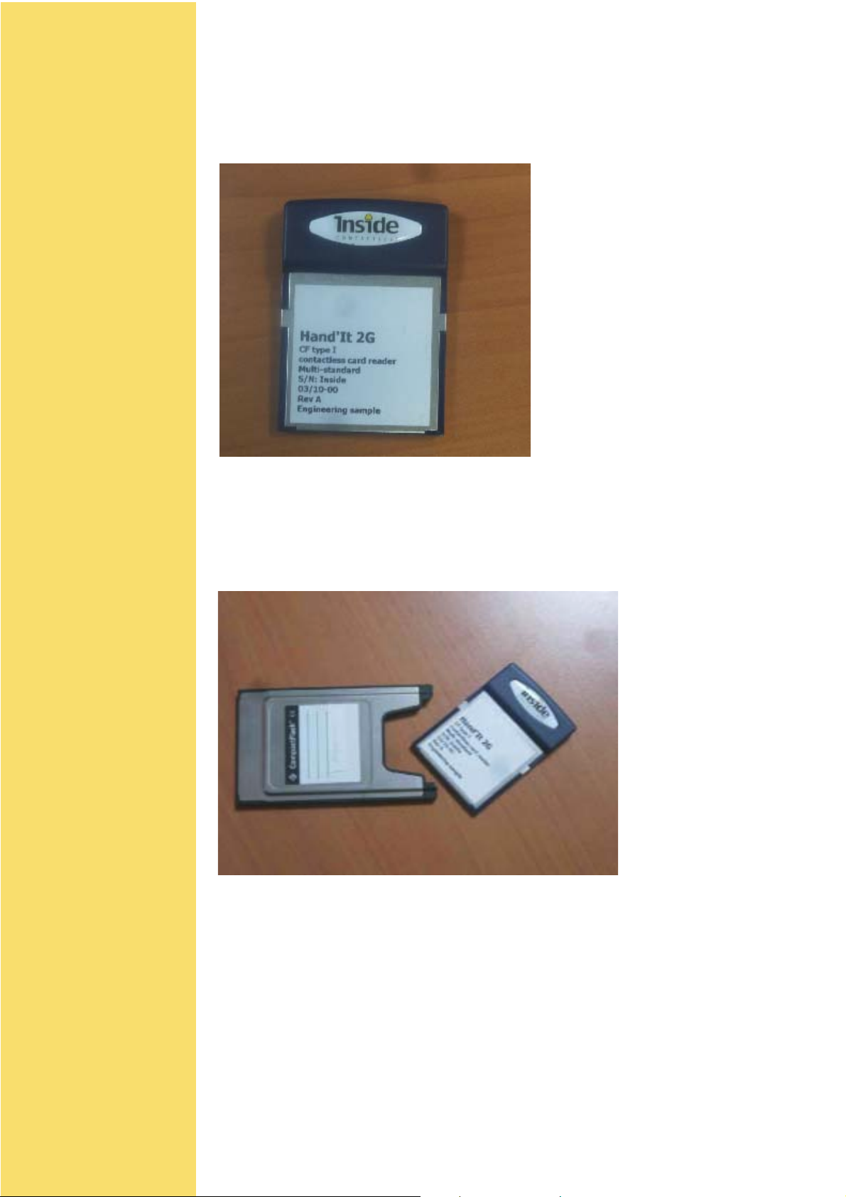
Hand’IT-2G
Compact Flash READER
13.56 MHz for ISO chips
- 14 443 type A and B
- 15 693
- FeliCa
Chips > Packaging > Readers > more...
DS 1
Page 2

Content
HAND-IT 2G Block Diagram 6
CHAPTER 1
HAND'IT-2G DESCRIPTION
HAND'IT -2G dimensions 7
Mechanical Interface – Top View 7
HAND'IT-2G with PCMCIA Compact Flash Adaptor (not supplied) 7
CHAPTER 2
HAND'IT-2G CONNECTION
Physical Description 8
Electrical Description 8
Power supply 8
Characteristics 8
8
Software & Drivers 9
9
Serial Interface 10
Character Format 10
Baud rate 10
How to reset HAND'IT-2G couplers 11
Software reset 11
Hardware reset 11
CHAPTER 3
COMMAND INTERFACE
REFERENCE MANUAL
HOST - COUPLER protocol 2
description 2
Coupler commands overview 5
SELECT_CARD 6
SELECT_PAGE 8
TRANSMIT 10
GET_RESPONSE 12
READ_STATUS 13
SET_STATUS 14
Hand’IT-2G - Preliminary Datasheet
Modifiable parameters 15
Coupler’s INPUTs AND OUTPUTS 16
EEPROM free area 16
Version 1.0
DS 2
Page 3

DISABLE_COUPLER 17
DISABLE_COUPLER ENHANCED 18
ENABLE_COUPLER 19
ASK_RANDOM 20
LOAD_KEY_FILE 21
SELECT_CURRENT_KEY 22
DIVERSIFY_KEY 23
GET_CONFIG 24
CHAPTER 4
USER’S GUIDE
Managing INSIDE chips 2
Security configuration 3
Selecting a chip 4
Selecting a page 5
Reading chip memory 6
Writing chip memory 7
Halting a chip 8
How to work with several chips in the field 9
Managing INSIDE’s chips protocols 10
Managing the security 11
INSIDE chips security 11
Key loading 13
How to set a key as the active one 14
How to authentify a chip 15
How to authentify a PAGE 15
Protecting the keys 16
Managing ST ANDARD chips protocols 17
Time out adjustment 17
15 693-3 protocol 17
ISO 14 443 type A 18
ISO 14 443 type B 18
FeliCa ( new version) 18
Managing the RF field 19
How to reset the RF field ? 19
How to asleep the coupler 19
How to wake up the coupler 19
APPENDIX A
HOW TO LOAD A KEY IN A COUPLER
Exchange key 21
Hand’IT-2G - Preliminary Datasheet
Version 1.0
General key loading procedure 21
Terminology and notation 22
Key loading step by step 22
Algorithms 23
DS 3
Page 4

Key permutation 23
Checksum byte calculation 23
Load key checksum calculation 23
APPENDIX B
ERROR CODE
Hand’IT-2G - Preliminary Datasheet
Version 1.0
DS 4
Page 5

Main Features
√√
√ Security management:
√√
!Security module
!Secure key loading
√√
√ Secured Key Storage
√√
√√
√ Contactless interfaces:
√√
!ISO 15 693
!ISO 14 443 type A
!ISO 14 443 type B
!FELICA
√√
√ Contactless transmission of data and energy supply
√√
√√
√ Carrier frequency: 13.56MHz
√√
√√
√ On board antenna
√√
√√
√ Transparent mode for contactless data exchange
√√
√√
√ Supply voltage: 5 or 3,3V
√√
TM
√√
√ Low power consumption < 50 mA
√√
√√
√ Idle mode < 5 mA
√√
√√
√ Stand-by mode < 50 µA
√√
√√
√ Small size: extended CF type I form factor (61 x 43 mm)
√√
√√
√ Operating temperature range: -20°C to +50°C
√√
√√
√ Emission approval* : FCC, IDA singapore, Canadian, CE
√√
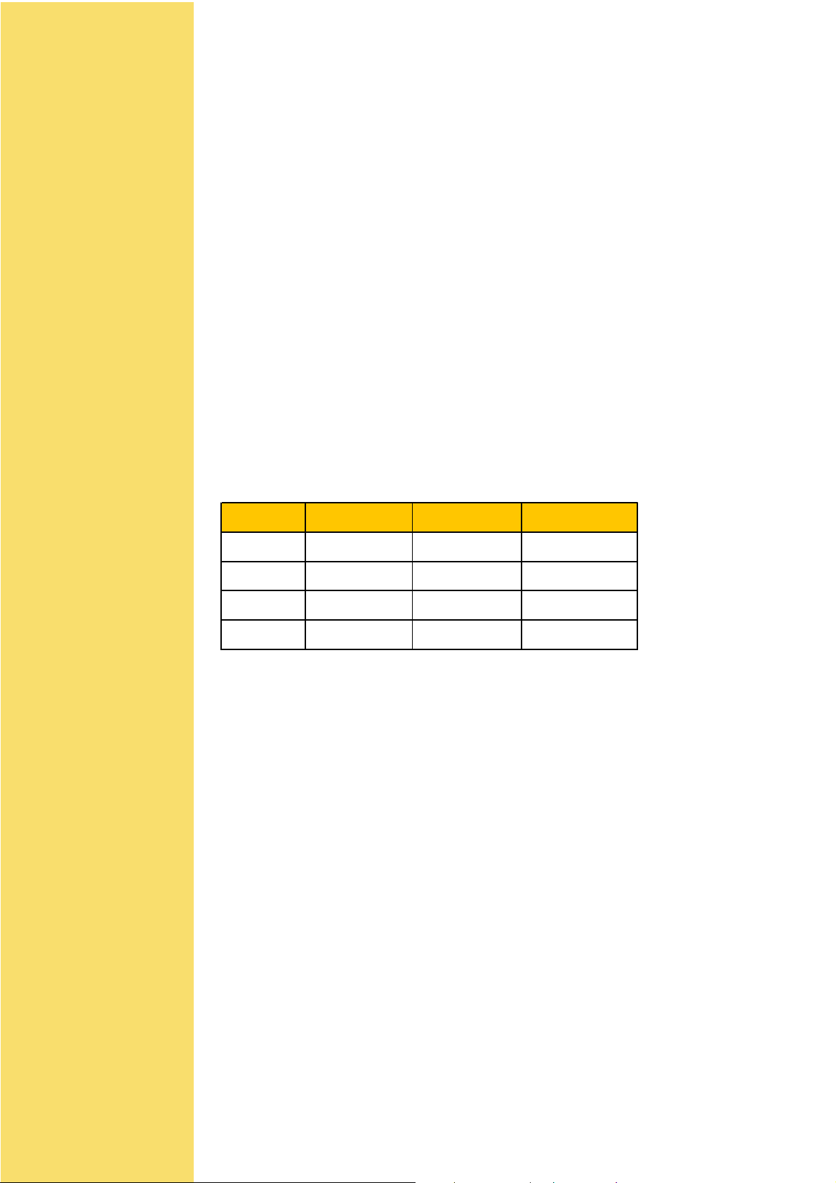
Product Ordering Code
Product Ordering code Package Tools
Proximi ty Coupl er Hand'IT-2G Hand'IT-2G/F CF -
-
Hand'IT -2G -Preliminary Datasheet
Version 1.0
DS - 5
Page 6

CHAPTER 1
HAND'IT -2G
DESCRIPTION
HAND'IT-2G couplers are developed by INSIDE contactless for
managing the RF communication interface with 13.56 MHz standard
chips.
They have the following features :
""
" Operating frequency 13.56MHz
""
""
" Host interface CF card
""
""
" Compatibility Windows 98/XP/Me/2000/PPC2002-
""
2003
""
" T arget applications Proximity and short range
""
applications
""
" Target chip All INSIDE’s chips, 15693 chips,
""
14443 chips (type A and type B),
FELICA
TM
Afterwards, the term «coupler» stands for an electronic board or
device that converts numeric commands into contactless chip
commands using the RF interface.
HAND-IT 2G Block Diagram
Hand'IT -2G -Preliminary Datasheet
Version 1.0
DS - 6
Page 7
HAND'IT-2G dimensions
Mechanical Interface – Top View
" HAND'IT size : L 61 mm * l 43 mm * h 3,3-8mm
HAND'IT-2G with PCMCIA Compact Flash Adaptor (not
supplied)
Hand'IT -2G -Preliminary Datasheet
Version 1.0
DS - 7
Page 8

CHAPTER 2
HAND'IT -2G CONNECTION
This chapter describes :
! How to power the coupler
! How to communicate with the coupler
Physical Description
The host is connected to the Compact Flash Hand’IT 2G using a standard 50pin
connector.
The host must be equiped with a CF+ type 1 or 2 slot.
Refer to the host user manual for the Compact Flash card insertion.
Electrical Description
The HandIT 2G acts as a standard PC Card A T A using I/O Mode.
Refer to PC Card standards for details.
Power supply
CHARACTERISTICS
To power up the coupler , just insert the device into a CF type I or II slot.
Note that opening the associated COM port will power on the device and closing will
Power it off.
Refer to the host operating system for more details.
Description M in. Typical M ax. Unit
DC voltage 3,135 3,3 3,465 V
RF ac t ive current 50 TBD mA
Idle Mode c urrent 5 TBD mA
St andby c urrent 50 TBD µA
Electrical characteristics
Hand'IT -2G -Preliminary Datasheet
Version 1.0
DS - 8
Page 9

Software & Drivers
System requirements
The Hand’It 2G works with laptops or PDAs running Microsoft Windows 98/2000/XP/CE
/Pocket PC2002&2003.
Pocket PC Users
PDA running Pocket PC don’t need any specific driver to manage the Hand’IT 2G as a
standard COM Port.
Depending on the device, the COM port number can take any value.
Refer to the Register DataBase to get the correct COM number under
HKEY_LOCAL_MACHINE\ DRIVERS\ACTIVE\xx
Search the Key with PnpId = Hand_It-INSIDE-D9A6
Y ou will find the COM number in the Name Field.
Laptops users
Y ou need to install the HandIT 2G drivers from the Inside installation disk
Insert the HandIT 2G into the laptop (using an CF to PCCARD adapter .).
Follow screen instructions and select the folder containing HandIT2G.inf file from the Ins-
tallation Disk.
The HandIT 2G will appear as a standard COM Port named Compact Flash HandIT.
Y ou can adjust COM settings from the hardware profil menu.
Coupler Communication
Once installed, the Hand’IT 2G works as a standard coupler connected to a serial COM
port.
Hand'IT -2G -Preliminary Datasheet
Version 1.0
DS - 9
Page 10
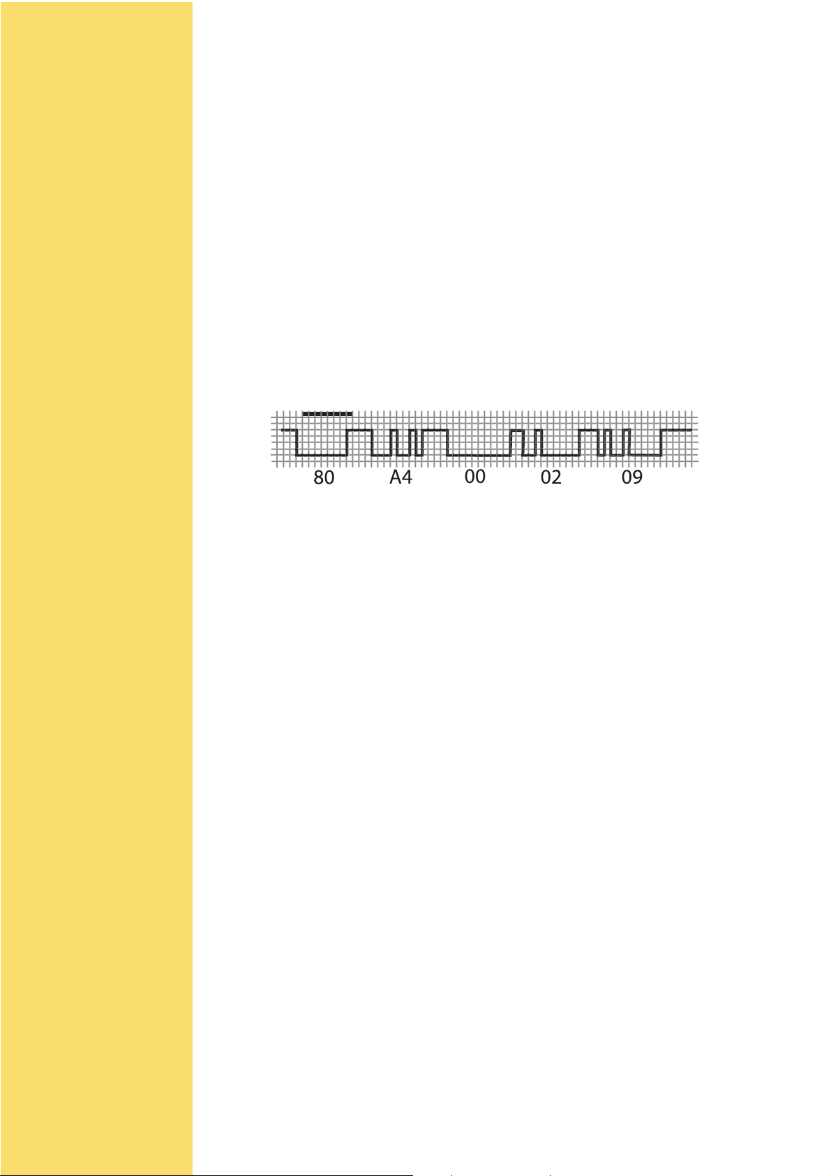
Serial Interface
8 bits
This interface allows a serial connection to the host via the CF interface:
Character Format
Data Rate 115200 baud (default value)
Parity Even
Number of bits 8
T ransmission Mode LSB first
Stop bits 2
Flow control none
SelectCard command frame
Baud rate
The default data rate is set at 115200baud, but this can be changed by software to select
following data rates :
! 9600
! 19200
! 38400
! 57600
! 1 15200
Version 1.0
Hand'IT -2G -Preliminary Datasheet
DS - 10
Page 11
How to reset HAND'IT-2G couplers
Resetting the coupler may be useful in two situation :
a. to set the parameters (speed, disable mode, protocol settings, keys ) to the defaults
values. All these values are stored in coupler’s internal EEPROM
b. if it is impossible to communicate with the coupler (bad setting for serial communication speed mainly)
SOFTWARE RESET
It is possible to reset the coupler’s EEPROM by sending 2 commands thanks to the SET
ST ATUS command.
Command = $80,$F4,$80,$3E,$01 - Data = $00
Command = $80,$F4,$80,$7E,$01 - Data = $00
Then the coupler has the default setting : 1 15200 bds, defaults protocols....
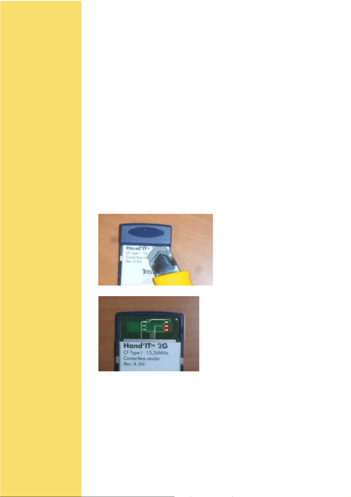
HARDWARE RESET
If for any reason it becomes impossible to communicate with the coupler, follow this
procedure :
• remove the hand’IT 2G from the CF slot
• remove the plastic top cover as shown
• connect the 2 reset pins as indicated in the drawing
• reinsert the Hand’IT 2G and open the COM port: it will start with the default factory
parameters
• remove the hand’IT 2G from the CF slot and the the reset pins connection
Hand'IT -2G -Preliminary Datasheet
Version 1.0
DS - 11
Page 12

CHAPTER 3
COMMAND INTERFACE
REFERENCE MANUAL
In this chapter you will find the command format, and the description
of all the commands used by the coupler.
User may refer to this chapter to find the following information :
!!
!
low level description of data exchange between coupler
!!
and host, mainly when using microcontroller or an
automat
!!
!
check the signification and/or a value of a command
!!
parameter
Coupler - Reference manual
Version 1.1
RM 1
Page 13
HOST - COUPLER protocol
DESCRIPTION
The commands are modeled on the ISO 7816 command set. This protocol is used by all
INSIDE"s couplers
A typical protocol exchange includes:
1. The host sends a command to the coupler
2. The coupler executes the command
3. The host receives a response from the coupler
Coupler command is always constituted of 5 bytes :
• CLASS : always 80h
• INSTRUCTION : command to be executed by the coupler (like SelectCard)
• P1 : Command parameter
• P2 : Command parameter
• P3 : Command parameter
Depending on the command, coupler answers data, status words.
There are 4 cases of data exchange:
Case Host to coupler Coupler to Host ISO Type
1 None None ISO None
2 None Yes ISO Out
3YesNoneISO In
4 Yes Yes ISO In / Out
Note : In case 4, data has to be sent and received from the coupler. With T=0 protocol, it
is not possible in a single command, so this command has to be split into 2 commands:
Coupler - Reference manual
Version 1.1
RM 2
Page 14
ISO In : The host sends a command + data and receives the status words.
ISO Out : The host sends a command and receives data + the status words.
Coupler with firmware former than 40-017F has only ISO NONE, ISO IN and ISO OUT
protocol available.
In all cases, status words are returned (SW1 and SW2).
Case 1: ISO None Data Exchange
Command
Host
Coupler
nb of bytes
Cla. Ins. P1 P2 P3
5 bytes
Case 2 : ISO Out Data Exchange - Coupler
Command
Host
Coupler
nb bytes
Class : always 80h
Instruction : command code
P1 & P2 : command parameters
P3: number of data bytes expected from the coupler
Cla. Ins. P1 P2 P3
Status words
SW1 SW2
2 bytes
""
" Host
""
Ack. Data
= Ins. data SW1 SW2
1 = P3
Status words
25
Ack. : coupler acknowledgement. It is always equal to the command code, except when
an error occurs. If the Acknoledgement value is different than the instruction byte, then
the received byte is the first byte of a status error code coded on 2 bytes.
Data : data sent to the host by the coupler. Size of the command has to be P3.
Status word : 90 00h if correct, error code.
Case 3: ISO In Data Exchange - Host
Command
Host
Coupler
nb bytes
Cla. Ins. P1 P2 P3 Data
""
" Coupler
""
Ack. Data
= Ins. SW1 SW2
1 = P3
Status words
25
Coupler - Reference manual
Class : always 80h
Instruction : command code
P1 & P2 : command parameters
Version 1.1
RM 3
Page 15
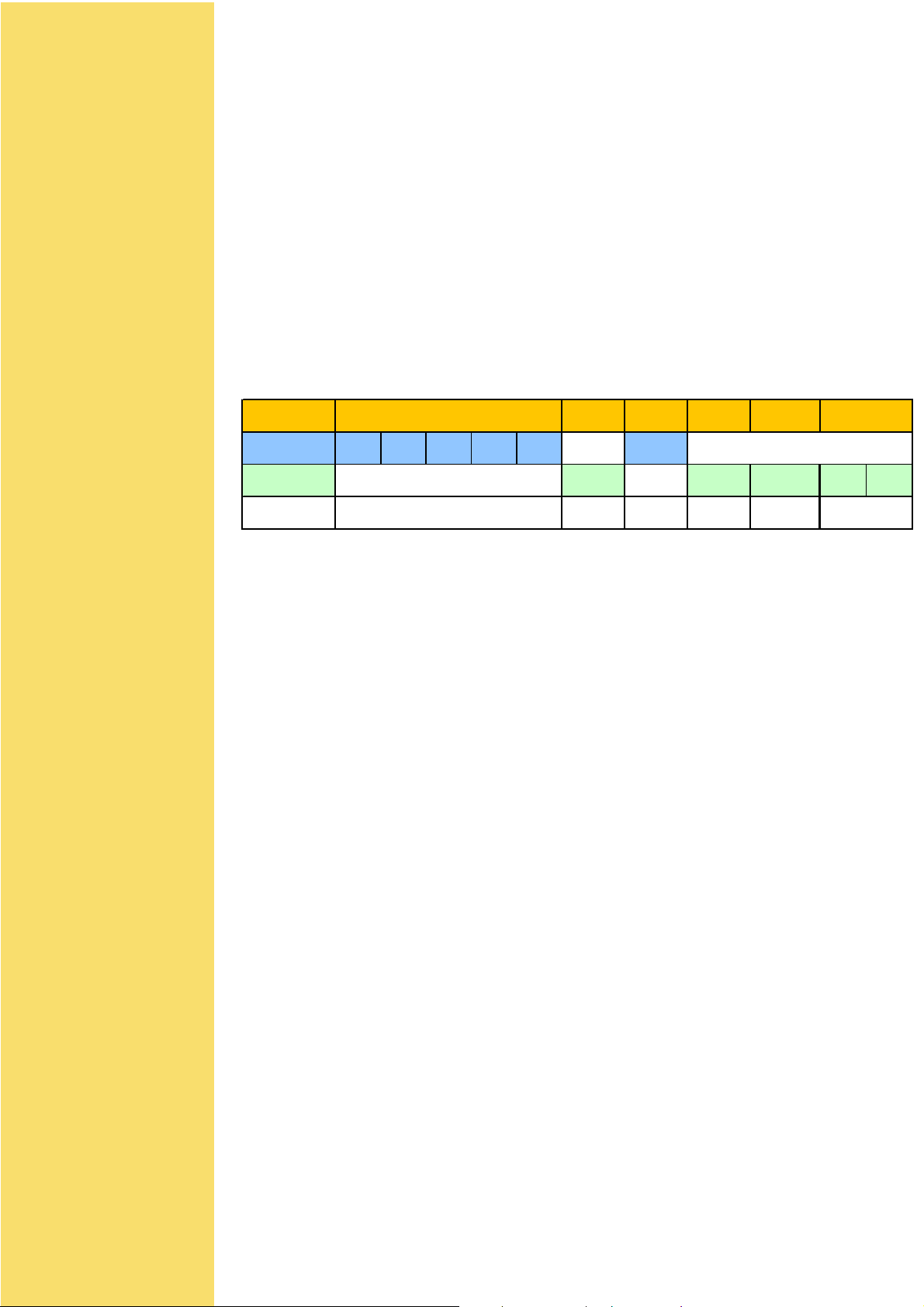
P3: number of data bytes sent to the coupler.
s
Ack. : coupler acknowledgement. It is always equal to the command code, except when
an error occurs. If Acknowledgement value is different than instruction byte, then the
received byte is the first byte of a status error code coded on 2 bytes.
Data : data sent by host to the coupler. Size of data array has to be P3.
Status word : 90 00h if correct / error code.
Error : If the Acknowledgement value is different than the instruction byte, then the received
byte is the first byte of a status error code coded on 2 bytes.
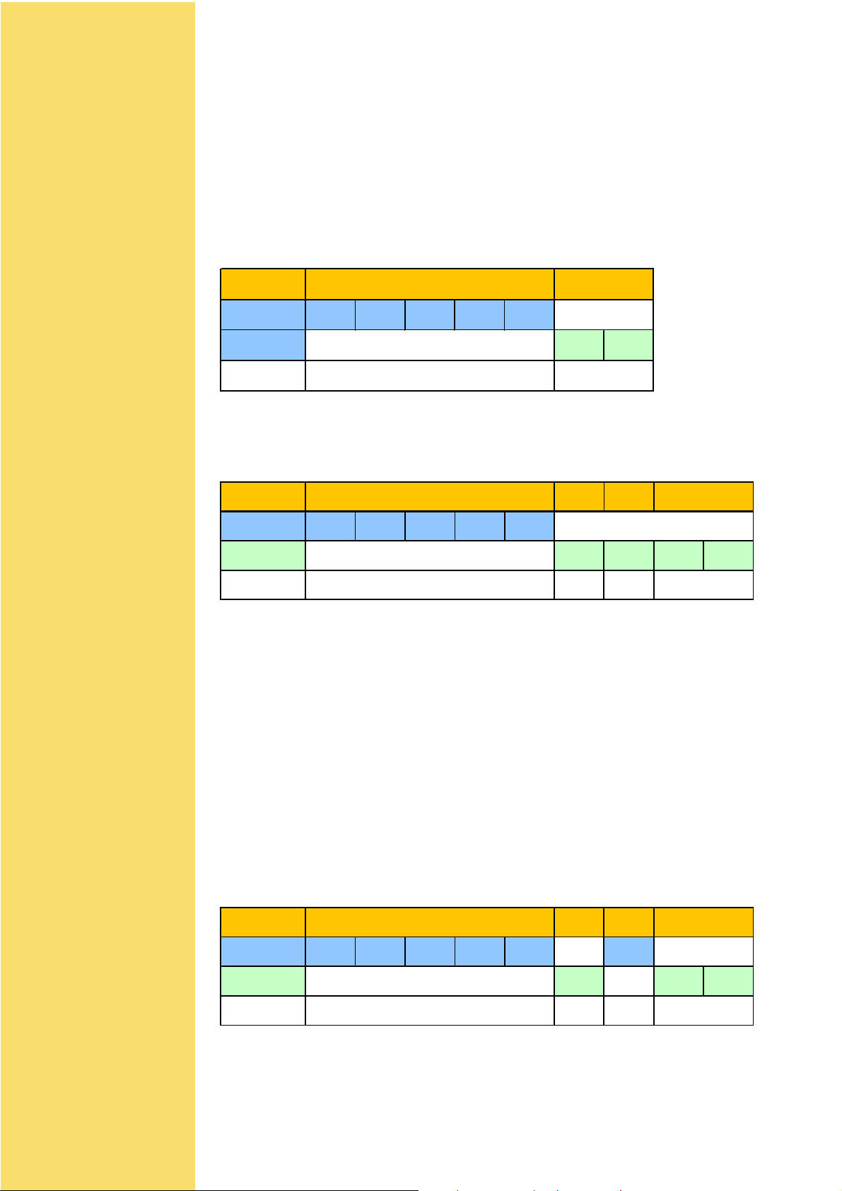
Case 4 : ISO InOut Data Exchange - Host
Command
Host
Coupler
nb bytes
Class : always 80h
Instruction : command code
P1 : command parameters
P2 : number of data bytes expected from the coupler.
P3 : number of data bytes sent to the coupler.
Ack. : coupler acknowledgement. It is always equal to the command code, except when
an error occurs. If Acknowledgement value is different than instruction byte, then the
received byte is the first byte of a status error code coded on 2 bytes.
Data : data sent to the host by the coupler. Size of the command has to be P3.
Status word : 90 00h if correct / error code.
Cla. Ins. P1 P2 P3 Data in
⇔⇔
⇔ coupler
⇔⇔
Ack. Data in Ack. Data out
= Ins. = Ins. Data out SW1 SW2
1 = P3 1 =P252
tatus word
Coupler - Reference manual
Version 1.1
RM 4
Page 16

Coupler commands overview
Command INS Description
SELECT_CARD "A4h" Selects one contactless card following list of
possible cards in the field
SELECT_PAGE "A6h" Selects a page in a multi-application chip
TRANSMIT "C2h" Sends and retrieve data from chip through
contactless interface : Transparent mode
GET_RESPONSE "C0h" Reads the internal buffer of the coupler to retrieve
chip answer for ISO 7816 T=0 protocol.
Command INS Description
READ_STATUS "F2h" Reads coupler status or EEPROM memory.
SET_STATUS "F4h" Sets the coupler status or write in EEPROM
memory.
DISABLE_COUPLER "ADh" Disables the coupler. it will only respond after a
ENABLE_COUPLER command.
ENABLE_COUPLER "AEh" Enable the coupler. It wakes up the coupler after
a DISABLE_COUPLER command.
Security module functions†:
Command INS Description
LOAD_KEY_FILE "D8h" Load new master keys for authentication
purposes.
ASK_RANDOM "84h" Ask for a random number from the coupler.
SELECT_CURRENT_KEY "52h" Select the key to be used for authentication
purposes.
Coupler - Reference manual
Version 1.1
RM 5
Page 17

SELECT_CARD
Use
Select a card in order to get the serial number. This command manages anti-collision and
authentication features.
This command is able to test several communication protocol. It answers the number of
protocol used to select the card.
Prototyping
# Command sent : A4h
# Command type : ISO out
Host 80h A4h P1 P2 P3
Coupler A4h Card type Serial number 90h 00h
Parameters
Bit 76543210
Function - - Key Auth Presel. Loop Halt W ait
P1: Parameter used for contactless configuration
IMPORTANT: " - " are reserved for future use, and values should be set to 0.
WAIT :
1: Wait until a card is selected or a character received from the host (e.g. PC).
0: Exit if no card is detected after 3 attempts.
Note: When SELECT_CARD uses the option ´LOOPª, the coupler sends
ACK=60h (See T=0 specifications) after each unsuccessful selection until
a card is selected. When a card is selected, ´90h 00hª is returned. In order
to stop this scanning, host has to send a byte through the RS232 interface.
HALT:
1: Halts card after selection for fast serial numbers capture.
0: No halt after selection.
LOOP:
1: returned a frame composed of ACK | CARD TYPE | SN | 9000h or wait character
60h
0: no loop performed.
PRE:
1: Increases pre-selection with INSIDE CONTACTLESS anti-collision and a large
number of cards.
0: Standard anti-collision (best for 5 cards max.).
Coupler - Reference manual
Version 1.1
RM 6
Page 18

AUTH:
1: Performs a standard INSIDE authentication.
Authentication is performed if the key is set as the current key.
Please refer to appendix A : ´How to low a keyª for key loading and key management
operations details.
0: Does not perform an authentication.
KEY:
1: Authenticates with Debit Key (Kd = Key 1) if AUTH is set.
0: Authenticates with Credit Key (Kc = Key 2) if AUTH is set.
P2: Parameter used for selecting the card types to be read
b7 - b4 b3 b2 b1 b0
0 Protocol 3 Protocol 2 Protocol 1 Protocol 0
INSIDE couplers manage the following protocols :
- Protocol 0 : ISO 14 443 type B & Inside anticollision (only for INSIDE chip)
- Protocol 1 : ISO 15 693 & Inside anticollision (only for INSIDE chip)
- Protocol 2 : ISO 14 443 type B-3
- Protocol 3 : User defined protocol - see ´Other ISO chip managementª chapter for more
information about Protocol 3 use.
If bit related to protocol x is set to one, coupler will run an anticollision using this protocol.
If several protocols are selected, coupler will test all of them, starting from protocol 0 to
protocol 3.
P3: Number of bytes to be return by the coupler
Set P3 = 09h for reading Pico Family Chips serial numbers.
Response: Card type (1 byte) and serial number (8 bytes)
Card type is the protocol number used by the card that has been selected for its answer.
For 15 693 INSIDE"s chips, card type value is 1 as protocol 1 is used for selection. This
value is the one to use to indicate protocol in the transmit command.
Coupler - Reference manual
Version 1.1
RM 7
Page 19

SELECT_PAGE
Use
This command is used to select and authenticate in an INSIDE multi-application chip
(8*2Ks...).
Prototyping
# Command sent : A6h
# Command type : ISO Out
Host
Coupler
80h A6h P1 P2 08h
A6h
Chip 's
configuration
block
90h 00h
Parameters
Bit
Function
P1: Parameter used for contactless configuration
b3 : Auth
0 - Does not perform authentication after PAGESEL.
1 - Performs authentication after PAGESEL
b2: Select Page
0 - Does not send the PAGESEL command before authentication
1 - Sends the PAGESEL command with page contained in P2 before authentication
Note : b2=b3=0 imply that no operation is performed
76543 2 10
----Auth
Page
selection
Protocol type
Coupler - Reference manual
Version 1.1
b1-b0: Protocol type:
This command can only work with PICO family chips
Contactless Communication Protocol
00 ISO14 443 B PICO family chips
01 ISO15 693 PICO family chips
10 ISO14 443 B-3
11 User"s protocol
RM 8
Page 20

P2 : Page number to select and authenticate and cryptographic key to use
Bit
Function
b7-b4 : Reader key number
Note : 0 correspond to Kd0, 1 to Kc0, Ö, 14 to Kd7 and 15 to Kc7.
This is the reader key number to use during authentication. The reader will use this
key number (EEPROM) to diversify and authenticate the requested page with Kd or
Kc.
b3 : Page"s key to use to perform the authentication
0 : authentication will be performed with page"s debit key.
1 : authentication will be performed with page"s credit key.
b2-b0 : Page number to select
P3 : Chip answer length
This parameter has to be set to 8 as the chip answers the page"s configuration block (8
bytes).
76543210
- Page numberReader key number
Coupler - Reference manual
Version 1.1
RM 9
Page 21

TRANSMIT
Use
Transmits data from the coupler to the chip and read back chip response.
This command is the one to use to read and write data in the chip.
Prototyping
# Command sent : C2h
# Command type : ISO In / Out
Host
Coupler
P1 : Defines the contactless communication protocol
P2 : Chip answer length
P3 : Chip command and data
80h C2h P1 P2 P3 Data
C2h Chip answer 90h 00h
Parameters
P1: Parameter used for contactless configuration
Bit
Function
b7: Send CRC:
1: The coupler automatically sends the CRC (function of the Data bytes) to the
chip. Coupler uses the CRC associated to the choosen protocol (bit 1 & 0)
0: Only P3 data bytes are sent.
b6: Compare CRC:
1: Compares the returned CRC with the expected value calculated by the coupler
(verify the data sent by the chip).
0: CRC is not checked.
7654 3 210
Send
CRC
Check
CRC
Time out
Send
signature
ISO
type
RF protocol
type
Coupler - Reference manual
Version 1.1
b5-b4: Time Out:
The time out value depends of the protocol used (b1 and b0 values).
The time out is the time from the command"s EOF (End Of Frame) to the chip
response SOF (Start of Frame).
Bits 4& 5
00 800 µs 200 µs
01 4 ms 1 ms
10 24 ms 6 ms
11 40 ms 10 m
Time-out
15 693
Time-out
14 443
RM 10
Page 22

b3: Send Signature:
1: Send a cryptographic signature calculated thanks to the coupler security module.
This option may be used only for UPDATE command performed on secure PICO
family chip. Set this value to 0 for non secure chip or any other manufacturer chips
0: Cryptographic signature is not sent.
b2 : HOST - COUPLER protocol type
1 : Communication is ISO IN-OUT. Coupler send back the data as soon as it
receives chip answer.
0 : Commucation between HOST and coupler follows the ISO 78-16 T=0 protocol.
Thus TRANSMIT command is only ISO IN, and user has to use the GET REPONSE
command to retrieve chip DATA from the coupler.
b1-b0: Protocol type:
Defines the contactless communication protocol number to be used. When
coupler"s EEPROM is set with the default values, the protocol types are as follows:
Contactless Communication Protocol
00 ISO14 443 B PICO family chips
01 ISO15 693 PICO family chips
10 ISO14 443 B-3
11 User protocol (default value : ISO 14 443 A-3)
P2 : Number of data bytes received from the chip after transmission of the
command.
If the Compare CRC bit of P1 is enabled, P2 should not include the CRC bytes.
Note: P2<=35 (23h).
P3 : Number of bytes in the data field of the command.
If the Send CRC or the Send Signature bit of P1 is enabled, P3 should not include the
CRC bytes or the signature.
Note: P3<=32 (20h).
Data: Commands and data to send to the chip
All PICOTAG commands are detailed in PICOTAG datasheet.
Response:
$ Chip answer
$ Status word.
Coupler - Reference manual
Version 1.1
RM 11
Page 23

GET_RESPONSE
Use
This command returns the value contained in the internal buffer of the coupler.
It has to be used to get chip answer when the TRANSMIT command is used with the ISO
IN type to retreive the chip answer.
Prototyping
# Command sent :C0h
# Command type : ISO out
Host
Coupler
80h C0h 00h 00h P3
C0h
Coupler
buffer
90h 00h
Parameters
P3: Number of bytes of the coupler response. It has to be less than 35 (23h).
Response : Coupler"s buffer and status words
Coupler - Reference manual
Version 1.1
RM 12
Page 24

READ_STATUS
Use
This command is used to get coupler parameters (communication speedÖ).
Prototyping
# Command sent : F2h
# Command type : ISO out
Host
Coupler
80h F2h P1 P2 01h
Parameters
P1: type of parameter to read
b7 - b2 b1 - b0
0 (RFU)
b1-b0 : Parameter location
$ 00 : Parameter value is read in coupler"s EEPROM (setting when power
on)
$ 01 : Coupler"s I/O
$ 10 : Reserved for Future Use
$ 11 : Parameter value is read in coupler"s RAM (current setting)
P2: set the parameter address to read
Valid values for P2 according to P1 value:
$ EEPROM: 00h to FFh.
$ I/O: 05h and 07h.
$ Parameter: 50h to 6Fh.
F2h
Parameter
location
bytes
Read
90h 00h
Coupler - Reference manual
Version 1.1
Response : byte value at the transmitted address + status word
Note: When reading the I/O, the Read byte returned indicates the IN1, OUT1, OUT2 pin
states as follows: (OUT2P is connected to VDD via a 1kŸ- resistor).
I/O Addressb7b6b5b4b3b2b1b0
05h : Output----OUT2OUT1--
07h : Input-------IN
RM 13
Page 25

SET_STATUS
Use
This command sets configuration parameters and coupler"s I/O :
# Communication speed
# Protocols
# State at Power ON
# 2 outputs & 1 input
The various parameters and data used by INSIDE couplers are stored in the EEPROM.
When coupler is powered on, a part of these parameters are load in coupler"s RAM, so
that parameters may be modified in coupler"s EEPROM and in coupler"s RAM.
For a given parameter, RAM and EEPROM address are the same. For example, speed
parameter is located at address 6Dh for both RAM and EEPROM.
! When updating a value in the coupler"s EEPROM, this value will be the default
value after turning the coupler on.
! When updating a value in the coupler"s RAM, this value will be the current value
until the next Power Off.
! When writing to EEPROM occurs, EEPROM parameters are reloaded into processor
memory (RAM).
Prototyping
# Command sent : F4h
# Command type : ISO In
Host
Coupler
80hF4hP1 P201h Data
F4h 90h 00h
Parameters
P1: Sets the type of configuration parameter to update
b7 b6 b5-b2 b1 - b0
Reset coupler
b7 : Resets coupler
if this bit is set to 1, coupler will fully reload EEPROM in RAM as if the coupler is powered
on.
Note : when b7 = 1, the coupler responds 3Bh 00h.
Reset magnetic
field
- (RFU) Address
Coupler - Reference manual
Version 1.1
RM 14
Page 26

b6 : Reset magnetic field
Magnetic field is cut for 20 ms.
When this bit is set to 1, coupler will execute no other action, including EEPROM or RAM
update.
b5-b2 : RFU (reserved for future use)
b1-b0 : Parameter location
# 00 : Parameter value is read in coupler"s EEPROM (setting when power
on)
# 01 : Coupler"s I/O
# 10 : Reserved for Future Use
# 11 : Parameter value is read in coupler"s RAM (current setting)
P2: Sets the parameter address to update
Valid values for P2 according to P1 value:
# EEPROM : 00h to 07h and 3Eh to FFh.
# I/O : 05h, 06h, 07h.
# RAM : 50h to 6Fh.
Response: Status words
MODIFIABLE PARAMETERS
User can change the following parameters in coupler"s memory :
# Protocols - Please refer to ´Managing ISO protocol with INSIDE couplerª application
note for more information about protocol management
# Serial communication speed - from 9600 to 424000 bauds depending on the
reader
Name Address State Hex. value Available on...
9600 57h
19200 2Dh
Serial
communication
speed
Note 1 : When updating the COMSPEED parameter, the coupler returns the Status Words
with the previous COMSPEED before the COMSPEED update.
6Dh All readers
38400 15h
57600 0Eh
115200 06h
Coupler - Reference manual
Version 1.1
Example : the baudrate is set to 9600 bauds and needs to be temporarily updated to 115
200 bauds.
Send a SET_STATUS command (80h F4h 03h 6Dh 01h & 06h). The coupler responds
(Status words) using 9600 bauds.
# State at power on - Is coupler emitting a field when it is powered on ? (please refer
to ENABLE and DISABLE command chapters)
RM 15
Page 27

Name Address State Hex. value Available on...
State at
power on
Note 2 : The ACTIVATE AT POWER ON parameter defines the state of the coupler when
you turn it on.
If you turn the coupler on and if 00h is written in the EEPROM at address 42h , it will be
´asleepª until you send an ENABLE_COUPLER command.
IMPORTANT NOTE : If change in the EEPROM is followed by a reset of the coupler
and if address 42h contains 00h then the coupler will be asleep until you send an
ENABLE command.
Enable 01h
All reader42h
Disable 00h
COUPLER"S INPUTS AND OUTPUTS
Please refer to chapter 1 for connection.
Reader Input / Output I/O address
OUT1 05h - Bit 1 Set Status
Command to
use
Value
M21xH
M22xH OUT 05h - bit 2 Set Status
M302H OUT 06h - bit 4 Set Status
OUT 2 05h - bit 2 Set Status
IN 1 07h - bit 0 Read Status
Set Status05hLEDACCESSO
EEPROM FREE AREA
User can use EEPROM bytes from 70h to 7Dh to write some data.
Bit at 0 : low level
Bit at 1 : High level
Byte value & color
04h : Red
08h : Orange
0Ch : Green
Coupler - Reference manual
Version 1.1
RM 16
Page 28

DISABLE_COUPLER
Use
The coupler goes in SLEEP mode that allows low power consumption and RF carrier is
desactivated.
After this command, the coupler will not respond to any command except the
ENABLE_COUPLER command.
A new feature available only on M21xH 2G is that coupler can detect if a card approach
the antenna and wake up on its own.
Prototyping
# Command sent : ADh
# Command Type : ISO none
Host
Coupler
80h ADh BCh DAh 01h
90h 00h
Parameters
Response: Status words
Note : It is possible using the SET_STATUS command to have the coupler in a sleep
mode each time it turns on. The coupler will then be asleep until you send an
ENABLE_COMMAND. Please refer to the SET_STATUS command for activating this
feature.
Coupler - Reference manual
Version 1.1
RM 17
Page 29

DISABLE_COUPLER ENHANCED
Use
As the DISABLE_COUPLER command, this specific version enables the user to asleep
the reader.
But M210H 2G and M260H 2G have the possibility to detect that a card approaches their
antenna.
As sooon as the card is detected, the coupler will turn the RF field on, and start a card
selection.
If no card answers to the anticollision process, the coupler go back asleep. If a card is
selected, then the coupler stay awake.
Prototyping
# Command sent : ADh
# Command Type : ISO none
Host
Coupler
80h ADh BCh P2 01h
90h 00h
Parameters
P2 : specify the anticollision to process when a card is detected. If several bit are set at 1,
all selected anticollision will be performed.
b7 b6 b5 b4 b3 b2 b1 b0
-0-Pulse
OUT1
ï If Antx bit is set, then the anti-collision x will be processed else not.
ï If no Antx is set, then the coupler will wake-up only by detecting a field change over
the reader.
ï If b4 is set, then the OUT1 PIN is set to high for 10 ms when a card is selected.
Note : It is possible using the SET_STATUS command to have the coupler in a sleep
mode each time it turns on. The coupler will then be asleep until you send an
ENABLE_COMMAND. Please refer to the SET_STATUS command for activating this
feature.
Ant3 Ant2 Ant1 Ant0
Coupler - Reference manual
Version 1.1
Note : This command is only available on :
- M210-2G
- ACCESSO-2G
RM 18
Page 30

ENABLE_COUPLER
Use
This command restores a normal coupler running, with RF emission.
This command can only be used after a DISABLE_COUPLER command or if the coupler
is desactivated after power on.
Prototyping
# Command sent : AEh
# Command type : ISO none
Host
Coupler
80h AEh DAh BCh 00h
3Bh 00h
Parameters
Response : Status words
The coupler will respond ´Instruction not recognizedª (6Dh 00h) if already activated.
Important note : You have to send the ENABLE_COUPLER command in a window
of 16ms. To be sure that your command will be received, send it twice. The time
between the sending of the 2 commands has to be less than 10 ms.
This is automatically done when using MX.Enable method (ActiveX component).
Coupler - Reference manual
Version 1.1
RM 19
Page 31

ASK_RANDOM
Use
This command returns an 8 bytes random value from the coupler.This command has to be
used to initialize the key loading procedure.
Prototyping
# Command sent : 84h
# Command type : ISO out
Host
Coupler
80h 84h 00h 00h 08h
Parameters
Response : Random number; Status words
84h Random number 90h 00h
Coupler - Reference manual
Version 1.1
RM 20
Page 32

LOAD_KEY_FILE
Use
This function loads into the coupler"s security module a key to be used for authentication
and security purposes.
Key loading is a security sensitive operation. In order to protect the confidentiality of the
keys transferred to the coupler, data is encrypted. A 4-byte checksum is also sent in
order to guarantee the authenticity of the data, which could be corrupted either through
transmission errors or by a deliberate attempt to fraud the system.
Refer to ´Coupler"s key loadingª chapter for more information about security and the way
to calculate encrypted key and checksum.
Prototype
# Command sent : D8h
# Command type : ISO In
Host
Coupler
80h D8h P1 P2 OCh Data
D8h 90h 00h
Parameters
P1 : Parameter used for key operations
00: Load and activate the key pointed by P2.
01: Deactivate the key pointed by P2 (Forbidden option to Exchange Key Ke).
02: Delete the key pointed by P2 (Forbidden option to Exchange Key Ke).
Others value are reserved for future use.
Notes:
With the 00 option, this command will replace the old value of the key with the new value.
With the 01 and 02 options, the command has to be sent with 12-byte data at any value
(Data = XX XX XX XX XX XX XX XX XX XX XX XX).
When a key is deactivated, you need to reload it to reactivate the key.
P2 : Key number.
00h - Exchange Key Ke: used for key loading operation.
01h - Debit Key Kd0
02h - Credit Key Kc0
03h - Debit Key Kd1
04h - Credit Key Kc1
.....
0Fh - Debit Key Kd7
10h - Credit key Kc7
Coupler - Reference manual
Version 1.1
Data:
This field contains:
# the 8-byte encrypted master key
# the 4-byte checksum
Response: Status Words
RM 21
Page 33

SELECT_CURRENT_KEY
Use
This function allows to choose a key for future authentications. A key that has been
deactivated or deleted cannot be selected. Only one of the 16 keys can be current at the
same time.
Prototype
# Command sent : 52h
# Command type : ISO In
Host
Coupler
80h 52h 00h P2h 08h 8 * 00h
52h 90h 00h
Parameters
P2 : Key number
01h - Debit Key Kd0
02h - Credit Key Kc0
03h - Debit Key Kd1
04h - Credit Key Kc1
.....
0Fh - Debit Key Kd7
10h - Credit key Kc7
Remark: if the specified key is deactivated, the status bytes returned is 6Bh 00h.
Coupler - Reference manual
Version 1.1
RM 22
Page 34

DIVERSIFY_KEY
Use
This function enables the user to calculate the result of key diversication with selected
chip serial number.
The key diversified value is used for authentication and signature calculation while writing
a secure chip.
This can have 2 uses :
- before an authentication (SELECT_PAGE or AUTHENTIFY command)
- to calculate the keys that will be written in a chip during a personalization phase (only
working with a dedicated personalization coupler)
Prototype
# Command sent : 52h
# Command type : ISO In
Host
Coupler
80h 52h 00h P2h 08h Chip serial number
52h 90h 00h
Parameters
P2 : Key number
01h - Debit Key Kd0
02h - Credit Key Kc0
03h - Debit Key Kd1
04h - Credit Key Kc1
.....
0Fh - Debit Key Kd7
10h - Credit key Kc7
Remark: if the specified key is deactivated, the status bytes returned is 6Bh 00h.
Coupler - Reference manual
Version 1.1
RM 23
Page 35

GET_CONFIG
Use
This command is used to read the ID of the MCU part.
Prototype
# Command sent : CAh
# Command type : ISO In
Host
Coupler
80h CAh 00h 00h 09h
Parameters
Data : MCU part"s ID
Code Info (1 byte) : RFU
CA ID (8) Code Info (1) 90h 00h
Coupler - Reference manual
Version 1.1
RM 24
Page 36

CHAPTER 4
USERíS GUIDE
In this chapter ou will learn how to use the coupler
to...
!Use INSIDE chip
!Manage the security
Chips and readers- USERíS GUIDE
Version 1.0
UG 1
Page 37

MANAGING INSIDE CHIPS
The various steps in INSIDEís chips management are the following :
!!
! Set the used key (if your application is secured)
!!
!!
! Select a chip
!!
!!
! If it is a multi-application chip, select the page in which you
!!
want to work
!!
! Read, Write data in the chip memory
!!
!!
! Halt the chip to enable another chip selection
!!
Using INSIDE couplers, authentication and signature calculations are
managed automatically by the SELECT_PAGE or the SELECT_CARD
command. Just indicate in these commands that you want to use the
security features.
In this chapter is just indicated the way and the functions and commands
to use to reach your goal. Please refer to the Reference Manuals for more
information about the functions and its parameters.
In this chapter you will also learn :
! !
! how to manage the various protocol at low level or with the
! !
activeX component
! !
! how to make a chips inventory and select a chip within several
! !
ones.
Chips and readers- USERíS GUIDE
Version 1.0
UG 2
Page 38

SECURITY CONFIGURATION
Before using the security features, please take a look at the ´Security managementª
chapter. You will find there basic principles on which is based INSIDE chips security.
If your application is secured, you have to ...
a. Load the key in the coupler. This operation has to be performed only once. As soon as
keys are loaded, they are stored in the couplerís EEPROM.
b. tell to the coupler which key you want to use for your application (Kd1, Kc1, Kd2 ...)
a. Loading the key...
You have to indicate the following parameter :
- Exchange key to enable you to load the key
- New key value
- Key number (is it ´Debit Key 3ª, ´Credit key 2ª)
!!
! ActiveX : Mx.KeyLoading method
!!
!!
! C Library : Clib_w_KeyLoading procedure
!!
!!
! Low level : LOAD_KEY_FILE command
!!
b. Activating the current key...
Two commands are available to tell to the coupler which key you want to use. One has
to be used before the selectcard command, and the other before the SelectPage or
Authentify command if you want to use a key different than the one used to authentify
the chip (or if you selected the card without authentication).
Use the following commands before the SelectCard command :
!!
! ActiveX method : Mx.CurrentKey property
!!
!!
! C Library : CLib_w_SelectCurrentKey procedure
!!
!!
! Low level : SELECT_CURRENT_KEY command
!!
Please refer to the chapter ´Managing the securityª for more details about the way it
works, and to the reference manual chapter for more details about the commands.
Use the following commands before the SelectPage and Authentify
commands :
!!
! ActiveX method : Mx.DiversifyKey property
!!
!!
! C Library : Clib_w_DiversifyKey procedure
!!
Chips and readers- USERíS GUIDE
Version 1.0
!!
! Low level : DIVERSIFY_KEY command
!!
Please refer to the chapter ´Managing the securityª for more details about the way it
works, and to the reference manual chapter for more details about the commands.
UG 3
Page 39

SELECTING A CHIP
During this operation, you will choose the protocol you want to use (14 443 type A, 14
443 type B or 15 693), and if you want to authentify the chip. The answer will give you the
protocol used by the chip, and its serial number
Security... P1 value Which protocol... P2 value
none 00h 14 443 B-2 01h
Kd au t he nticat i on 30h 15 693 02h
Kc aut hent i c at i on 10h 14 443 B-3 04h
Then use the following command :
!!
! ActiveX method : Mx.SelectCard (P1, P2, Type_SerialNumber)
!!
!!
! C Library : Clib_w_SelectCard (P1, P2, Type_SerialNumber)
!!
!!
! Low level : SELECT_CARD : 80h A4h P1h P2h 09h...
!!
Note 1 : Coupler will answer the protocol number used to communicate with the chip,
and the chip serial number. This ´protocol numberª is the value to use with the TRANSMIT command as ´protocol valueª
Note 2 : The above table show 2 protocols ISO 14 443 type B
!!
! 14 443 type B-2 : RF protocol is the one defined in the 14 443 B standard level 2,
!!
and anticollision is INSIDE contactless one.
!!
! 14 443 type B-3 : RF protocol follows the 14 443 B standard level 2, and anticollision
!!
is defined in 14 443 B standard level 3.
Chips and readers- USERíS GUIDE
Version 1.0
UG 4
Page 40

SELECTING A PAGE
If you are using a Multi-application chip ( 8*2K for example ) you have to select the page
in which you want to work.
The SelectCard command selects by default page 0. The SelectPage command enables
you to work in all other pages. It will manage the authentication if the page is secured.
You have to enter... You will get...
- page number - page configuration block (block 1)
- key to use for authentication
- protocol to use
Then use the following command :
!!
! ActiveX method : Mx.SelectAuthPage (Key number , PageNumber, ConfigBlock)
!!
!!
! C Library : Clib_w_SelectAuthPage (Key number, Protocol,
!!
PageNumber, ConfigBlock)
!!
! Low level : SELECT_PAGE
!!
Host
Coupler
The following table gives you parameters to select and authenticate a secured page. P2
values are just examples.
Protocol P1 value... Page & key number P2 value...
14 443 B 0Ch Key Kd1 & P age 1 21h
15 693 0Dh Key Kc1 & Page 1 31h
14 443 A 0Eh Key kd7 & P age 7 E7h
80h A6h P1 P2 08h
A6h
Note : if the page is secured, use the
diversify command to select in the coupler the
key that will be use for the authentication.
configuration
Chip 's
90h 00h
block
Chips and readers- USERíS GUIDE
Version 1.0
UG 5
Page 41

READING CHIP MEMORY
You will find a full memory description in the chip datasheet, but the easiest way to
discover the chip memory is to use the MX3 software (PICO MEMORY page).
You have to enter... You will get...
- block number - memory data
- protocol to use
Then use the following command :
!!
! ActiveX method : Mx.ReadBlock (BlockStart, BlockCount, ChipResponse)
!!
Mx.Read property : ActiveX component optimizes reading
speed by using READ or READ4 chip command depending on chip possibilities.
!!
! C Library : Clib_w_ReadBlock (BlockStart, BlockCount, Protocol,
!!
ChipResponse)
Clib_w_ReadBlockBy4(BlockStart, BlockCount, Protocol,
ChipResponse)
!!
! Low level : TRANSMIT command + 0Ch chip command (single read)
!!
+ 06h chip command (read4)
All communication with a chip is done thanks to this command, including INSIDEís chips.
You will find there how to read one block with the 15 693 standard.
Host
Coupler
You can also use the Read4 chip command :
Host
Coupler
Note : To use another protocol, just change the bit in P2 parameter.
14 443 B-2 : Use 80h C2h C4h...
14 443 B-3 : Use 80h C2h C6h...
80h C2h C5h 08h 02h 0Ch Addh
C2h Chip's ans wer 90h 00h
80h C2h C5h 20h 02h 06h Addh
C2h Chip's ans wer 90h 00h
Chips and readers- USERíS GUIDE
Version 1.0
UG 6
Page 42

WRITING CHIP MEMORY
When writing data to a memory block you have to know if you are communicating to a
secure or non secure chip. Parameters will be different as you ask the coupler to send or
not the signature to authenticate the data you want to write (this is automatically managed
by the ActiveX component).
!!
! ActiveX method : Mx.WriteBlock (BlockStart, BlockCount, BlocksValue)
!!
!!
! C Library : Clib_w_WriteBlock (BlockStart, BlockCount, Protocol, Auth,
!!
BlocksValue)
!!
! Low level : TRANSMIT command + 87h chip command
!!
This command enables you to write one block. The following example are for a 15 693
communication.
Non secure chips
Host
Coupler
80h C2h E5h 08h 0Ah
C2h
87h Addh
&Data
Written
Secure chips
Host
Coupler
Note : To use another protocol, just change the appropriate bit in P2
parameter :
Non secured chip : 14 443 B-2 : Use 80h C2h E4h...
Secured Chip : 14 443 B-2 : Use 80h C2h 6Ch...
80h C2h 6Dh 08h 0Ah
C2h
14 443 B-3 : Use 80h C2h E6h...
14 443 B-3 : Use 80h C2h 6Eh...
87h Addh
&Data
Written
data
data
90h 00h
90h 00h
Chips and readers- USERíS GUIDE
Version 1.0
UG 7
Page 43

TIPS : to halt the chip
as soon as you get its
serial number, use P1
parameter in the
SELECT_CARD
command
HALTING A CHIP
The following command halts the current selected chip :
!!
! ActiveX method : Mx.Halt
!!
!!
! C Library : Clib_w_Halt (protocol)
!!
!!
! Low level : TRANSMIT command + 00h chip command
!!
Host
Coupler
Note : To use another protocol, just change the appropriate bit in P2
parameter :
14 443 B-2 : Use 80h C2h 30h...
14 443 B-3 : Use 80h C2h 32h...
80h C2h 31h 00h 01h 00h
C2h 90h 00h
Chips and readers- USERíS GUIDE
Version 1.0
UG 8
Page 44

TIPS : The low level
command
SELECT_CARD
includes an option that
halts the chip as soon
as it is selected. This
enables to earn time
by avoiding to send the
HALT command. Just
use the following P1
parameters : P1 =
02h.
HOW TO WORK WITH SEVERAL CHIPS IN THE FIELD
Here is the basic algorithm to get serial numbers of all chips in a given RF field :
Select card
No cardselected
Store chip serial
number in a table
Halt the selected chip
Select the chip you
want to work with
Chips inventory
Make a loop with the SELECT_CARD COMMAND with HAL T option enable (P1 = 02h).
Chip selection with its serial number
Use the following command to select a given chip thanks to its serial number. The chip
will answer you its serial number.
!!
! ActiveX method : Mx.ReSelect (ChipSN)
!!
!!
! C Library : Clib_w_ReSelect (ChipSN)
!!
!!
! Low level : TRANSMIT command + 81h chip command
!!
C2h
81h & Serial
Number
Serial
number
90h 00h
Host
80hC2hC5h08h09h
Chips and readers- USERíS GUIDE
Coupler
Version 1.0
Replace C5h by C4h (C6) to use 14 443 type B-2 (type B-3) protocol.
UG 9
Page 45

MANAGING INSIDEíS CHIPS PROTOCOLS
Low level command and C library
Protocols are always indicated in the command parameters (P2 for SELECT_CARD, P1
for TRANSMIT). You will find the appropriate value in this Userís Guide, and in the
description of each command in the ´Reference manualª.
ActiveX component
There are 2 command types :
- Card selection
- Select page, read, write...
Card selection
When selecting a card, you set the protocol to use in P2 parameter of the Mx.SelectCard
method. Coupler is able to test several protocols, and return the protocol use for card
detection.
Other operation (Read, Write, SelectPage etc...)
For any other operation, use the ActiveX propertie Mx.MxProtocolIndex to set the
protocol you want to use.
This property is automatically set after a SelectCard command thanks to the value returned
by the coupler indicating the protocol use for card selection.
If you want to change communication protocol when using a dual protocol chip
(PICOPASS - 15 693 & 14 443 type B), just change this protperty value to the desired
one, and all activeX command for INSIDE chip will use this protocol.
Chips and readers- USERíS GUIDE
Version 1.0
UG 10
Page 46

INSIDE
security protects
memory from REA-
DING and/or WRITING.
Security
control e-purse
(stored value) manage-
ment
MANAGING THE SECURITY
INSIDE chips security is based on secret keys that protect and authentify the chip content.
On one hand, keys are stored in the chip. On the other hand, coupler includes a security
module in which are stored the application keys.
Security is based on checking that keys are the same in the chip and in the coupler.
First paragraph explains on what is based our security and what it is for :
# Authentication
# Signature
# Diversified keys
The following paragraphs explain how to :
# load the key into the coupler / SAM
# select and / or authenticate a chip with a given key
Security is
based on :
- key diversification
- authentication
-signature
Key diversifi-
cation implies that
each security
calculation is different
for each card
INSIDE CHIPS SECURITY
Security consists in protecting memory access and e-purse use by secret keys. User
will be able to modify card content only if the coupler contains same secret keys as
PICO chip.
Security is checked several times :
##
# Authentication : Just after having selected the chip user has to perform an
##
authentication before being able to access any memory data.
##
# Signature : for any memory modification the chip user has to send a signature
##
calculated as a function of sent data, secret keys and chip serial number. Thus it
is impossible to modify the chip content without knowing the application keys.
In each security calculation, a diversified key is being used, based on the chip serial
number and the application key.
All security calculations are automatically manage by INSIDEís couplers.
Key diversification
To ensure a reliable security, every security operation (authentication, signature
calculation) is based on diversified key value.
The diversified key is an 8 bytes result of calculation including chip serial number and
key value.
Thus, 2 chips using same keys contain different diversified key values. This ensures
that it is not possible to repeat some sequence registered on one card on another card.
Chips and readers- USERíS GUIDE
Version 1.0
Secret K ey
Ch ip se ri al num ber
%
+
x
DES
Key
fortification
algorythm
Diversifi ed Key
UG 11
Page 47

Authentication
protects the memory
from reading and
writing
Authentication
Authentication algorithm performs a mutual authentication.
The principle is as follows : Data are exchanged then both device perform secret
calculations on them to obtain 2 results on 4 bytes. Authentication is done if they get the
same results. The chip first checks couplerí s response then reader verifies chipís results.
1. Coupler and chip
exchange data
Data (64bits) Random (32 bits)
Signature
when writing
increases memory
content security
Diversified
secret key
(64 bits)
2. Both coupler and
chip calculate 2
results on 4 bytes
Diversified
secret key
Coupler
Note :
R1 R2 R1 R2
Diversified key is written in
the chip during personalization
phase, and calculated after
each card selection by the
coupler (div. key depends on
3. The chip verifies the
coupler's result 1, then
send Result 2 if OK
4. The coupler checks
chip's answer (Result 2)
the chip serial number)
Signature
Each time you want to send data to the chip, a 32 bits signature is automatically calculated
and added. Signature calculation takes into account the diversified key value (result of
operation between key value and chip serial number) and the data. Chip will check the
signature to allow data writing. This ensures very good security on the chip content.
Chips and readers- USERíS GUIDE
Version 1.0
K ey Value Ch ip serial number
Diversified key value
Signature
Data
Coupler
Host
Signature cal c ulat ion princi ple
Data &
signature
Chip
UG 12
Page 48

First step in
security is to load the
secret keys into the
coupler
KEY LOADING
T o perform this complex operation, use the function supplied with the libraries (C Libraries,
ActiveX component). Y ou will find encryption algorithm in annex. C source code is provided
in the C libary, and ActiveX component manage automatically all security calculation.
You need to give the following parameter :
# Key number
# Exchange Key
# New Key value
! ActiveX method : Mx.KeyLoading
Use Mx.KeyLoading (KeyNum, LoadingType, ExchangeKey,NewValue) method to
load the key in the coupler at the appropriate place.
Keynum may have to following value :
- mpkPiKd (i=0 to 7)
- mpkPiKc (i=0 to 7)
Example : to load the default keys as keys 6 using the default exchange key ...
Mx.KeyLoading (mpkP6Kd, mklmXORKe,´$5C$BC$F1$DA$45$D5$FB$5Fª,
´$F0$E1$D2$C3$B4$A5$96$87ª)
Mx.KeyLoading (mpkP6Kc, mklmXORKe,´$5C$BC$F1$DA$45$D5$FB$5Fª,
´$76$65$54$43$32$21$10$00ª)
! C Library : Clib_w_KeyLoading
Clib_w_KeyLoading (KeyNum, LoadingType, ExchangeKey,NewValue)
! Low level : LOAD_KEY_FILE
Calculate the Encrypted key thanks to the C library algorythm (see annexe A) and use
the LOAD_KEY_FILE command...
Host
Coupler
P2 : Key number
00h - Exchange Key Ke: used for key loading operation.
01h - Debit Key Kd0
02h - Credit Key Kc0
03h - Debit Key Kd1
04h - Credit Key Kc1
0Fh - Debit Key Kd7
10h - Credit key Kc7
80h D8h 00h P 2 OCh Encrypt ed k ey
D8h 90h 00h
.....
Chips and readers- USERíS GUIDE
Version 1.0
UG 13
Page 49

Second step:
tell the coupler which
key has to be used
HOW TO SET A KEY AS THE ACTIVE ONE
A - Before SelectCard command
! ActiveX component : Mx.CurrentKey
Possible values are :
- mpkPiKd (i=0 to 7)
- mpkPiKc(i=0 to 7)
! C Library : Clib_w_SelectCurrentKey
Clib_w_SelectCurrentKey (KeyNum)
! Low level : SELECT_CURRENT_KEY command
Host
Coupler
P2 : Key number
00h - Exchange Key Ke: used for key loading operation.
01h - Debit Key Kd0
02h - Credit Key Kc0
03h - Debit Key Kd1
04h - Credit Key Kc1
0Fh - Debit Key Kd7
10h - Credit key Kc7
80h 52h 00h P2h 08h 8 * 00h
52h 90h 00h
.....
B - Before SelectPage and Authentify command
At this stage you need to precise both the key number and the chip serial number (as
you may be working with several chips).
Actually this operation is performed automatically by the selectCard command as it
knows the key number thanks to the CurrentKey property, and the Serial Number is
given by the chip during the selection phase.
When using a standard coupler, the DiversifyKey command returns a useless data
(random number). The returned data are used only with a personalisation coupler . More
information are given in the personalisation kit.
Chips and readers- USERíS GUIDE
Version 1.0
! ActiveX component : Mx.DiversifyKey
Mx.DiversifyKey (KeyNum, Chip Serial Number, Databack)
! C Library : Clib_w_DiversifyKey
Clib_w_DiversifyKey (KeyNum, Chip Serial Number, Databack)
! Low level : DIVERSIFY_KEY command
Host
Coupler
P2 : Key number
00h - Exchange Key Ke: used for key loading operation.
01h - Debit Key Kd0
02h - Credit Key Kc0
03h - Debit Key Kd1
04h - Credit Key Kc1
0Fh - Debit Key Kd7
10h - Credit key Kc7
80h 52h 00h P2h 08h
.....
52h 90h 00h
Serial
Number
UG 14
Page 50

Last step :
Tips : Key
diversifica-
tion is
automatically
done by the
select card
command
Tips :
Key diver-
sification
has to be done
only once. Y ou
donít need to use
the Diversify
command as soon
as you work with
the same chip
and the same
key
Authentication is
performed during chip
selection and/or page
selection
HOW TO AUTHENTIFY A CHIP
Authentication may be done while selecting the card (or the page). It can also be done
later, for example when you want to work with both Credit key and Debit key authentication.
!
ActiveX component : Mx.SelectCard
SelectCard (30h ...) authenticates selected chip with Kd
SelectCard (10h ...) authenticates selected chip with Kc
! C Library : Clib_w_SelectCard
Clib_w_SelectCard (SelectMode , ChipType, TypeSN)
SelectMode = 30h : Authentify with the chip debit key
SelectMode = 10h : Authentify with the chip credit key
! Low level : SELECT_CARD
80h A4h 10h P2 09h => Authenticate with Kc
80h A4h 30h P2 09h => Authenticate with Kd
HOW TO AUTHENTIFY A PAGE
Authentication follows the same principle as for the SelectCard authentication.
If you want to use a different key than the one used during the card selection, or if
selection has been done without you have to use the DiversifyKey command to set a key
as the active key if you want to change the active key.
! ActiveX component :
Mx.DiversifyKey (KeyNum, Chip Serial Number, Databack)
SelectAuthPage (Key, Page, BlockConfig)
! C Library :
Clib_w_Mx.DiversifyKey (KeyNum, Chip Serial Number, Databack)
Clib_w_SelectAuthPage (Key, Page, BlockConfig)
! Low level : DIVERSIFY_KEY & SELECT_PAGE
DIVERSIFY_KEY
Host
Coupler
80h 52h 00h P2h 08h
52h 90h 00h
Serial
Number
Version 1.0
Chips and readers- USERíS GUIDE
P2 : key number
SELECT_PAGE
Host
Coupler
80h A6h P1 P2 08h
A6h
Chip 's
configuration
block
90h 00h
UG 15
Page 51

P1 : contacless configuration
P2 : key and page number
PROTECTING THE KEYS
Thus all the security depends on making sure that these keys are kept secret. To ensure
a good secury, key loading has to be done in a secure environment.
The key loading procedure ensures that :
1 - nobody decrypts the key loaded in the coupler by listenning to the HOST -COUPLER
communication
2 - nobody records and uses the communication between HOST and COUPLER to load
keys in another coupler
To protect the communication, all data exchange is ciphered thanks to an exchange key
known only by the coupler. Therefore, nobody will be able decipher serial communication and find the application key value
Protect key storage (coupler, security module) so that
nobody can use your keys.
Use our coupler security protection features or store coupler or SAM keys in a secured
place.
To ensure a very good security to your application, contact us so we help you to give to
your system the security it deserves.
Chips and readers- USERíS GUIDE
Version 1.0
UG 16
Page 52

MANAGING STANDARD CHIPS PROTOCOLS
This chapter explains how to communicate with any chips that follow the 13.56MHz
standards : 15 693, 14 443 Type A and B. More over, you will find there how to
communicate with the FeliCa chip (SONY).
Note : userís will find there the commands to use to send byte to the chip, and to get the
chip answer, but we will not mention the way to manage these chips. User has to refer to
the chip datasheet or ISO standards to find more information about these chips.
TIME OUT ADJUSTMENT
When communicating with a chip, and particularly a microprocessor, user may need to
increase the time out value.
The TimeOut configuration enables the user to change the value of the TRANSMIT
command to be sure that no ISO command will fail because a too short timeout.
Users can change 4 timeout values corresponding to the 4 Timeout "slot s" that one can
use in TRANSMIT command:
ï Timeout 0 (command timeout option = b00) : Address h68
ï Timeout 1 (command timeout option = b01) : Address h69
ï Timeout 2 (command timeout option = b10) : Address h6A
ï Timeout 3 (command timeout option = b11) : Address h6B
Where "b" prefix is for binary value, "h" is for hexadecimal
T o put a specific value for one of these TimeOut "slots", developper can use the following
formulas:
ISO 14443 (A-B) : TimeOut = X . 380µs + 200µs
ISO 15693 : TimeOut = (X << 2) . 380µs + 200µs
Where X is the value of the byte and << is the operation that execute a binary right shift
of the byte value.
15 693-3 PROTOCOL
This example shows how to configure the protocol, then how to send the INVENTORY
command.
Public sub Sample_15693()
ë Configure USER protocol as 15693
Mx.MxUserProtocol = mupISO_15693_3_10pc
ëLow level command : use the SetStatus function
ëMx.SetStatus &H3, &H5E, &H21
ëMx.SetStatus &H3, &H5F, &H31
' Send Inventory command "1 slot" to retrieve chip serial number
Command = "$36$01$00$00"
CommandSize = &H04
AnswerSize = &H0A
UserProtocol = &HF3
Chips and readers- USERíS GUIDE
Mx.Transmit UserProtocol, AnswerSize, CommandSize, Command, ChipAnswer
' Send slot marker for anticollision management
Mx.Transmit &H73, &H0A, &H00, ´ª, ChipAnswer
Version 1.0
End Sub
UG 17
Page 53

ISO 14 443 TYPE A
Public sub Sample_14443_A()
ë Configure USER protocol as 14443-A level 3
Mx.MxUserProtocol = mupISO_14443A_3
' Low level : use the set status command
ëMx.SetStatus &H03, &H5E, &H32
ëMx.SetStatus &H03, &H5E, &H12
ëMx.SetStatus &H03, &H64, &H63
ëMx.SetStatus &H03, &H65, &H63
' Use the SelectCard command to manage anticollision
Mx.SelectCard &H00, &H08, Type_SN
'Send the RATS command :
Buffer length = 32
Name the card as card 0
Command = "$50$00"
CommandSize = &H02
AnswerSize = &H06
UserProtocol = &HF3
Mx.Transmit UserProtocol, AnswerSize, CommandSize, Command, ChipAnswer
End Sub
ISO 14 443 TYPE B
Public sub Sample_14443_B()
ë Card selection with the select Card command : manage the anticollision
Mx.SelectCard &H00, &H04, Type_SN
ëSend REQB command
Command = "$05$00$00"
CommandSize = &H03
AnswerSize = &H0C
UserProtocol = &HF2
Mx.Transmit UserProtocol, AnswerSize, CommandSize, Command, ChipAnswer
End Sub
FELICA ( NEW VERSION)
' Low level : use the set status command to configure the protocol
Mx.SetStatus &H03, &H5E, &H79
Mx.SetStatus &H03, &H5E, &H02
Mx.SetStatus &H03, &H64, &H00
Mx.SetStatus &H03, &H65, &H00
' Send a command to the chip and retrieve the answer
Command = "$06$00$FF$FF$00$01"
CommandSize = &H06
AnswerSize = &H12
UserProtocol = &HF7
Chips and readers- USERíS GUIDE
Mx.Transmit UserProtocol, AnswerSize, CommandSize, Command, ChipAnswer
Version 1.0
UG 18
Page 54

MANAGING THE RF FIELD
Possible operations you can perform on the RF field are the following :
# Cut RF emission, mainly when couplers are powered on battery
# Start RF emission
# ´Resetª RF field (i.e. cut it for 20 ms in order to reset any halted chip in the field)
HOW TO RESET THE RF FIELD ?
This command will cut the RF field for 20 ms in order to reset all chips that are in the
field.
!!
! ActiveX method : Mx.ResetField
!!
!!
! C Library : Clib_w_ResetField ()
!!
!!
! Low level : SET_STATUS command
!!
tsoH h08 h4F h04 h00 h10 h00
relpuoC h4F h09 h00
HOW TO ASLEEP THE COUPLER
Just use the disable command which will cut the RF field so that no energy is wasted.
!!
! ActiveX method : Mx.Disable
!!
!!
! C Library : Clib_w_Disable ()
!!
!!
! Low level : DISABLE command
!!
tsoH h08 hDA hCB hAD h00
relpuoC h09 h00
HOW TO WAKE UP THE COUPLER
!!
! ActiveX method : Mx.Enable
!!
!!
! C Library : Clib_w_Enable ()
!!
!!
! Low level : ENABLE command
!!
tsoH h08 hEA hAD hCB h00
Chips and readers- USERíS GUIDE
Version 1.0
relpuoC h09 h00
Important note
Low level command : You have to send this command in a window of 16 ms so that the
coupler catches it. To be sure that this command is detected, send it twice, with no more
than 10 ms between the 2 commands sending. This is automatically managed by the
ActiveX method.
UG 19
Page 55

APPENDICES
Chips and readers- USERíS GUIDE
Version 1.0
UG 20
Page 56

APPENDIX A
Reader
New key
value (Kx)
Exchange
key (Ke)
Exchange
key (Ke)
Ask random
Calculate the
session key
Encrypt the new
key value
Calculate
encrypted key
checksum
Load encrypted
key and
checksum
Decrypt new key
value
Calculate
checksum
Compare
checksum
Calculate the
session ley
Host
Random
(Rnd)
HOW T O LOAD A KEY IN A
COUPLER
This procedure consists in several operations on the key. The final result will be sent to
the coupler using the Loag_Key_File function.
EXCHANGE KEY
To ensure the security, an exchange key will protect all key loading operations.
This key is in the coupler memory and has 2 functions :
- only host knowing this key will be able to modify the Debit and Credit keys.
- New key value are encrypted with this exchange key so it is not possible to
read the new value on the serial line.
You have to know this exchange key to modify the value of any other key. For any
modification, the Exchange key is managed exactly as the Debit key and the Credit key
: you have to use the Key Loading Procedure described in the next paragraphs.
GENERAL KEY LOADING PROCEDURE
Before the key loading starts with the LOAD_KEY_FILE command, the host must
generate a session key . This key is generated by the encryption of the current Exchange
Key (Ke) with an 8-byte random number.
Chips and readers- USERíS GUIDE
Version 1.0
UG 21
Page 57

TERMINOLOGY AND NOTATION
Adding p after the key name means that the key is permuted.
Adding chk means that the 8th byte replaced by the Checksum byte value.
A C before the key name means that the key has been encrypted.
Abbreviation Meaning
K
ex
Exchange Key.
Kexp Permuted Exchange Key.
Kexp_chk Kep with the 8th byte replaced by the Checksum byte value.
Rnd Random number.
K
x
Master key. (Kx equals to Kd or Kc)
Kxp Permuted master key. (Kxp equals to Kdp or Kcp)
CKxp Encrypted permuted master key. (CKxp equals to CKdp or CKcp)
SK Session key.
CHK 4-byte checksum.
KEY LOADING STEP BY STEP
We assume that the default keys are used.
STEP DESCRIPTION Example
Step 1 : Get a random number from the coupler
80h 84h 00h 00h08h. The coupler ans wer a
Send
!
Send the
Ask_Random
command
random number.Forthis example,we ass um e that
Rnd = 00 00 00 00 00 00 0 0 00.
Step 2 : Calculat e t he S essio n Key
The session key is define by the f ollowi ng formula :
SK = Kexp_chk ⊕ Rnd (⊕ : bit to bit x-or
operation)
K
p_chk means that we ha ve to permute Kex then
ex
to r ep lace th e 8
Per mut e the exc ha nge k e y to get K
!
replac e the 8
!
to get K
Calculate the session key SK = 6E FD 46 EF CB B 3 C8 75
!
This calculation include the exchange keythrough
the sess i on key(SK). This ins u re the protection of
the new key value.
p = SK ⊕ Kxp (⊕ : bit to bit x-or operation) CKdp = 91 F2 75 B A CB 43 04 20
CK
x
Per mut e the new k ey valu e K
!
Make a bit to bit X-OR operation with the
!
sessio n key SK
Chips and readers- USERíS GUIDE
Calculate the CheckSum
!
Send the co mmand to t h e c oup ler .
!
Load_Key_File
th
byt e b y the checksum byte
th
byt e by the chec ksum byte
p_chk
ex
Ste p 3 : Calcu late t he Encry pted maste r key
Step 4 : Send t he
(CKxp + CheckSum)
to get Kxp
x
pKexp = 6E FD 46 E F CB B 3 C8 OB
ex
K
p_chk = 6E FD 46 E F CB B 3 C8 75
ex
Load_Key_File
CheckSum
Send
73 27 F F 01
command
= 73 27 FF 0 1
80 D8 00 01 0C & 91 F2 75 BA CB 43 04 20 &
Version 1.0
UG 22
Page 58

ALGORITHMS
KEY PERMUTATION
Proceed as described below to permute a key.
Example: Permute the key Kex.
Kex = 0x5C 0xBC 0xF1 0xDA 0x45 0xD5 0xFB 0x5F
(0x5F)
(0xFB)
(0xD5)
(0x45)
(0xDA)
(0xF1)
(0xBC)
(0x5C)
01011111
!
11111011
!
11010101
!
01000101
!
11011010
!
11110001
!
10111100
!
01011100
!
$$$$$$$$
0x6E 0xFD 0x46 0xEF 0xCB 0xB3 0xC8 (0xF4)
Replace the last byte by :
Kexp = 0x6E 0xFD 0x46 0xEF 0xCB 0xB3 0xC8 0x0B
0xF 4 = 0B
CHECKSUM BYTE CALCULATION
Proceed as described below to calculate a key checksum byte.
Note: the ⊕ symbol means a bit to bit x-or operation.
Example:
K = 0x5C 0xBC 0xF1 0xDA 0x45 0xD5 0xFB 0x5F
Kp = 0x6E 0xFD 0x46 0xEF 0xCB 0xB3 0xC8 0x0B
Checksum = 0x6E ⊕ 0xFD ⊕ 0x46 ⊕ 0xEF ⊕ 0xCB ⊕ 0xB3 ⊕ 0xC8 = 0x8A
Checksum = 0x8A = 0x75
and then,
Kxp_chk = 0x6E 0xFD 0x46 0xEF 0xCB 0xB3 0xC8 0x75
Chips and readers- USERíS GUIDE
Version 1.0
LOAD KEY CHECKSUM CALCULATION
! Complete the 5 command bytes with 3 bytes 00 so to get 8 bytes
! Calculate RES = (Command bytes) ⊕ Kxp.
! Calculate the checksum CHK = Most Significant 4-Bytes(RES) ⊕ Least Significant
4-Bytes(RES).
UG 23
Page 59

Example:
The checksum when sending the default Debit Key Kd is :
Command = 80 D8 00 01 0C 00 00 00
Kdp = FF 0F 33 55 00 F0 CC 55
RES = 7F D7 33 54 0C F0 CC 55
CHK = 73 27 FF 01
MSB(RES) 7F D7 33 54
⊕ LSB(RES) 0C F0 CC 55
________________________________
CHK = 73 2 7 FF 01
Chips and readers- USERíS GUIDE
Version 1.0
UG 24
Page 60

APPENDIX B
ERROR CODE
When an error occurs, coupler response is only status words SW1 SW2. No data is
returned.
The following table sums up the various values.
SW 1 S W2 Error description
90h 00h
67h 00h
6Bh 00h
6Eh 00h
6Dh 00h
69h 82h
98h 35h
6Ah 82h
62h 00h
Command successful
Comm on status e rrors
Data length, P3 incorrect
Parameters P1, P2 incorrect
Class not rec ogni zed
Instruc tion not rec ognised, parity error
Se curi ty e r rors
Card not identified (CRC or authentication
problem)
Command flow incorrect
Execution error
Card not found
EEPROM erro
Chips and readers- USERíS GUIDE
Version 1.0
UG 25
 Loading...