


AirGoggle NVC100/110
Network Video Camera
User’s Manual
Inscape Data Corporation
Copyright, 2004, All Rights Reserved
Inscape Data Corporation

NVC100/110 User’s Manual
g
g
g
g
g
g
g
g
The NVC100/110 is designed for indoor use only. When using the NVC100/110 outdoors or in an
environment that exceeds the limited range, you must separately use a water-resistant case.
Be careful not to cause any physical damage by dropping or throwin
keep the NVC100/110 out of reach from children.
Do not disassemble NVC100/110. Doing so will caus e you to be excluded from After Service.
Use only the power adapter provided with the NVC100/110.
If you would like to use the NVC100/110 for security monitorin
within the country.
This equipment has been manufactured and tested to comply with the limits for a Class B
di
ital device, pursuant to Part 15 of the FCC Rules. These limits are designed to provide
reasonable protection a
equipment
and used in accordance with the instructions, may cause harmful interference to radio
communications. However, there is no
particular installation. If this equipment does cause harmful interference to radio or
television reception, which can be determined by turning the equipment off and on, the
user is encoura
measures :
! Reorient or relocate the receiving antenna.
! Increase the separation between the equipment and rec eiver.
! Connect the equipment into and outlet on a circuit different from that to which
! Consult the dealer or an experienced radio/TV technician for help.
ainst harmful interference in a residential installation. This
enerates, uses and can radiate radio frequency en ergy and, if not installed
ed to try to correct the interference by one or more of the followin
the receiver is connected
Directions
the NVC100/110. Especially
, please check the legal regulations
Note
uarantee that interference will not occur in a
2222 of
of 51
51
of of
5151

NVC100/110 User’s Manual
A
A
ny changes or modifications in this device which are not expressly approved by Inscape Data could void the user's
authority to operate the equipment
This appliance and its antenna must not be co-located or operating in conjunction with any other antenna or transmitter.
minimum separation distance of 20 cm must be maintained between the antenna and the person for this appliance to
satisfy the RF exposure requirements.
Date Rev No Description
2004-7 1.1 Initial Release
2004-12-29 1.3 Supporting PC - Removed Window 98SE
Modifications and new features in Admin page
Network, Motion detection, Encryption, Upgrade
Caution
Revision History
3333 of
of 51
51
of of
5151

NVC100/110 User’s Manual
1. INTRODUCTION ........................................................................................................................................................6
1.1. OVERVIEW..................................................................................................................................................................6
1.2. FEATURES OF NVC100/110...................................................................................................................................6
1.3. APPLICATIONS OF NVC100/110............................................................................................................................6
2. PRODUCT DESCRIPTION......................................................................................................................................8
2.1. CONTENTS..................................................................................................................................................................8
2.2. PREVIEW.....................................................................................................................................................................8
2.3. PHYSICAL DESCRIPTION ............................................................................................................................................9
2.4. PC REQUIREMENTS..................................................................................................................................................12
2.5 QUICK INSTALLATION GUIDE ...................................................................................................................................12
3. CONNECTING THE NVC100/110....................................................................................................................15
3.1. CONNECTING TO LAN..............................................................................................................................................15
3.2. CONNECTING TO XDSL MODEM............................................................................................................................. 16
Table of Contents
3.3. CONNECTING TO CABLE MODEM............................................................................................................................17
4. IP-INSTALLER ..........................................................................................................................................................19
4.1. MAIN WINDOW OF THE IP-INSTALLER ...................................................................................................................19
5. CONFIGURING THE A/V SERVER IN ADMINISTRATIVE MODE ...................................................20
5.1. LOG ON.....................................................................................................................................................................20
5.2. BASIC SETUP............................................................................................................................................................22
5.3. NETWORK CONFIGURATION ....................................................................................................................................24
5.4. CCD ADJUSTMENT..................................................................................................................................................27
5.5 USER ADMIN & TIME SETUP....................................................................................................................................30
5.6 SENSOR & CAPTURE SETUP .....................................................................................................................................32
5.7. ALARM DEVICE SETUP.............................................................................................................................................34
5.8. MOTION REGION SETUP..........................................................................................................................................35
5.9. PTZ SETUP...............................................................................................................................................................36
5.10. ENCRYPTION SETUP...............................................................................................................................................38
5.11. UPGRADE & RESET ...............................................................................................................................................40
5.12. STATUS REPORT.....................................................................................................................................................42
6. TIPS FOR USING THE NVC100/110.............................................................................................................43
4444 of
of 51
51
of of
5151

NVC100/110 User’s Manual
6.1. ALARM-IN AND ALARM-OUT.............................................................................................................................43
6.2. TROUBLE SHOOTING................................................................................................................................................46
6.3. WEB VIEWER............................................................................................................................................................48
6.4. HOW TO UPGRADE YOUR NVC100/110 SYSTEM..............................................................................................50
5555 of
of 51
51
of of
5151

NVC100/110 User’s Manual
1. Introduction
1.1. Overview
The NVC100/110 is a state-of-the-art network video camera (and simultaneously a 1-channel A/V
server) which transmits both video and audio data in real time with high resolution at a high
frame rate. This is possible through MPEG4 CODEC technology, which provides data transmission
at high compression rates with high data resolution via networks. The NVC100/110 can be
connected, controlled, and monitored from a remote location through an IP address. Unlike CCTV
or DVR, the NVC100/110 is easy to install and also cuts costs and space without any additional
installation. Based on Embedded Software Solution (Embedded Web Server, Embedded
Streaming Server, Network Protocol), the NVC100/110 ensures high performance and stability
and provides integration of various Internet solutions.
1.2. Features of NVC100/110
# 1 channel real time audio/video streaming based on MPEG4 video and ADPCM audio.
# 1 channel bi-directional audio between the 100/110 and the client PC for two-way
communication
# The viewer assists recording and playback functions.
# 1-alarm sensor input/1 relay output
# Motion detection (Up to 3 motion detection regions)
Motion detection can initiate video recording, which is sent to the user through the FTP and (or)
E-mail.
# Resolution:
NTSC Video: 640x480 (VGA, for still image/small motion), 640x240, 320x240 (QVGA)
PAL/SECAM: 704x576 (for still image/small motion), 704x288, 352x288 (CIF)
# Remote P/T/Z control
# Remote software upgrade ov er network
# Easy to use with a convenient user interface
1.3. Applications of NVC100/110
# Security surveillance (buildings, stores, factories, parking lots, banks, government facilities,
military, etc.)
# Real time Internet bro a dcasting (resort areas, events, etc.)
# Remote monitoring (hospitals, kindergar tens, traffic, public areas, etc.)
6666 of
of 51
51
of of
5151

NVC100/110 User’s Manual
# Teleconference (bi-directional audio conference)
# Remote learning
# Weather and environmental observation
7777 of
of 51
51
of of
5151

NVC100/110 User’s Manual
2. Product Description
2.1. Contents
Open the package and make sure it contains the following:
Components Description Remarks
Power adapter
AC power cable AC 250V, 10A~16A
Quick Reference Guide Warranty Information
Mounting Stand
2.2. Preview
NVC100/110 IP-Installer NVR100 Software
NVC MPEG4 Network Camera
Input: 100~250V 50-60Hz
Output: +12V, 1.0A
LAN cable 6ft. LAN cable – crossover type
CD-ROM Software & User’s Guide
Antenna 5 dBi Omni-antenna NVC110W only
NVC100 : Fixed Iris Lens
NVC110 : Auto Iris Lens
NVC110P includes PoE
power injector module
For direct connection
between the server and
PC.
NVC100: Fixed Iris Lens
NVC110: Auto Iris Lens
NVC110P : NVC110+PoE
NVC110W : Wireless NVC
PC software to view and record
PC software to allocate an IP
address to the NVC100/110
8888 of
of 51
51
of of
5151
the A/V streaming data
transmitted from the
NVC100/110

NVC100/110 User’s Manual
2.3. Physical description
2.3.1. Front View
Microphone
Microphone
MicrophoneMicrophone
Lens
Lens
LensLens
Status Indicator LED
Status Indicator LED
Status Indicator LEDStatus Indicator LED
Figure 2-1. Front view of NVC100
# Lens Assembly:
NVC100 has fixed focal (6mm), fixed iris lens with C/CS mounting converter and NVC110 has
vari-focal (3.5 ~ 8mm) auto iris lens with a CS type mounting fixture. It can be replaced with
other lens types with CS mounting.
#
# Status Indicator LED: Status indicator LED shows the status of the NVC100/110 in 3
##
CS Lens Mount Ring
CS Lens Mount Ring
CS Lens Mount RingCS Lens Mount Ring
different colors.
1 Green: Green color indicates that the NVC100/110 is in normal operating condition. A
2 Red: A red light flickers or stays continuously on when the hardware of NVC100/110 is
continuous green light indicates that the NVC100/110 is ready for transmitting
data. A flickering green light means that someone is connecte d to NVC100/110.
in abnormal condition.
9999 of
of 51
51
of of
5151
NVC100/110 User’s Manual
3 Orange: An orange light flickers or stays continuously on when the software of the
NVC100/110 is in abnormal condition.
#
# Microphone: Picks up sound from the environment for transmission over the network.
##
#
# Mount Ring: Used for attaching the lens unit to the NVC100/110.
##
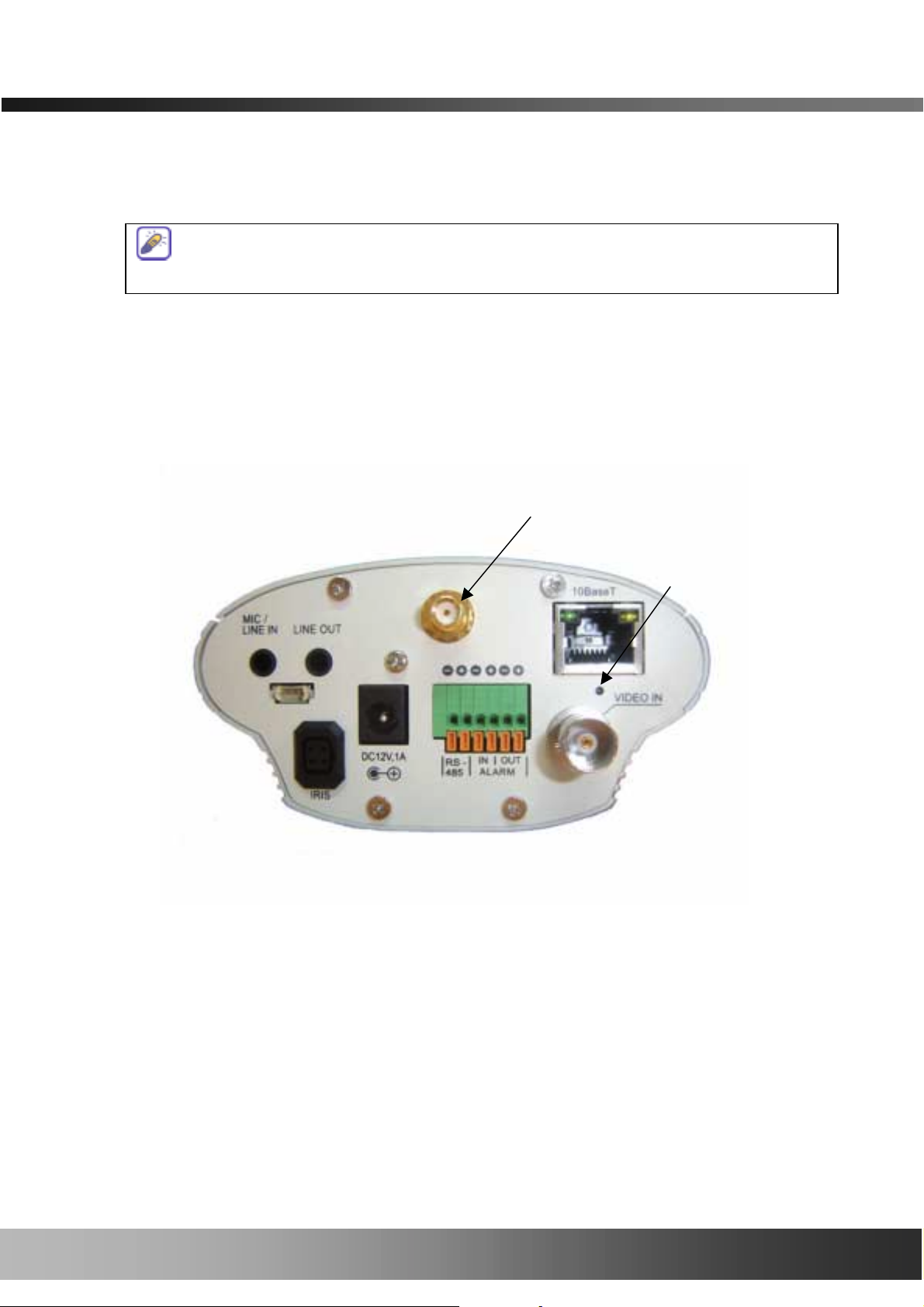
2.3.2. Rear panel
The status indicator LED temporarily lights red then returns to green when applying
power to the NVC100/110, which is normal.
Antenna Connector
for NVC110W
Factory Default
Reset
Figure 2-2. Rear Panel of NVC100/110
# MIC/LINE IN: Is used to connect an external audio source or microphone to the
NVC100/110.
# LINE OUT: Is used for connecting external speakers with the built-in amplifier. Audio from a
remote site is output through Line Out in bi-directional audio mode.
Use a standard stereo earphone jack for the connection.
10
10 of
of 51
of of
51
5151
1010

NVC100/110 User’s Manual
# 10Base-T: 10Mbps Ethernet connec tor (RJ-45).
# LINK LED: A gre en light means that the network cable is in normal condition.
# LAN LED: When there is traff ic on the LAN, a y ellow light flickers.
# RS-232 (3 pins): Used only by developers for modifying a program.
# DC12V, 1A: Power input of the NVC100/110- 12V/1A.
#
# DC-IRIS: Plug in the cable attached on the standard DC-Iris lens (Apply for NVC110).
##
#
# RS-485 and ALARM IN/OUT: Is used for connecting P/T/Z and alarm devices to
##
NVC100/110. Pin assignments are:
Pin 1 RS-485 Negative (-) input
Pin 2 RS-485 Plus (+) input
Pin 3 Alarm In (-)
Pin 4 Alarm In (+)
Pin 5 Alarm Out (-)
Pin 6 Alarm Out (+)
$ RS-485: Used for connecting Pan/Tilt/Zoom devices having an RS-485 interface
standard.
$ Alarm In: It is used for c onnecting external alarm sensors such as the infrared
sensors, heat sensor, magnetic sensors, etc.
$ Alarm Output: It is used fo r connect ing extern al al arm gen erato rs suc h as si rens,
flashing light, etc. When activated, relay output configures a closed circuit
# VIDEO-IN : External Video input (composite NTSC, P AL, SECAM)
# Factory Default Reset : Press and hold for 5 second to make fact ory default configuration
# Antenna Connector : Connect 5dBi antenna supplied with NVC110W (RP-SMA)
11
11 of
of 51
of of
51
5151
1111

NVC100/110 User’s Manual
2.4. PC Requirements
Streaming A/V data from the NVC100/110 can be observed through the NVR100 software
program, which is a viewing & recording program that runs on a PC. Minimum requirement of the
PC is described below:
Minimum Recommended
CPU Pentium III 700 Pentium IV 1.2G above
Main Memory 128 MB 256MB above
Operating system* Windows 98 SE. Windows 2000 or later
Web browser Internet Explorer 5.0 Internet Explorer 5.0 above
Resolution 1024 X 768 1600 X 1200
Network 10 Base-T Ethernet 10/100 Base-T Ethernet
* Operating systems supported: Windows 98 Second edition
Windows ME
Windows 2000 Professional
Windows XP Professional / Windows XP Home Edition
2.5 Quick Installation Guide
Brief information for rapid installation is provided in this section. For more detailed information,
refer to the pertinent documents provided with the product, or refer to Inscape Data’s home page
(http://www.InscapeData.com).
1. Apply power to the NVC100/110.
2. Connect NVC100/110 to your PC or network by using one of the following
methods:
i. Connect your PC and NVC100/110 using the Cross Type LAN cable provided with
NVC100/110 or
ii. Connect the NVC100/110 and your PC to an Etherne t using Direct T ype cable.
3. Install “IP installer” and “NVR100” on your PC.
Detailed information for installing these programs can be found in the IP-Installer
User’s Guide and the NVR100 User’s Guide, respectively.
4. Assign an IP address to the NVC100/110 using the IP installer.
Identify the type of the network environment and set up the IP address. A detailed
process for setti ng up the IP address can be found in th e IP-Installer User’s Guide. If
the network type is xDSL or cable modem, you will need supplementary information
12
12 of
of 51
of of
51
5151
1212

NVC100/110 User’s Manual
provided by your ISP.
5. Connect to NVC100/110 in Administrator Mode for initial parameter set-up.
All parameters are set to the factory default state when the NVC100/110 is delivered to
you. You are asked to configure the system for your environment in administration mode.
Detailed information for using the administration mode can be found in [5. Configuring
the A/V Server in Administrative Mode]. The parameters in the following table should
be set up with the proper values. Detailed information for the parameters in Administrator
Mode can be found in [5. Configuring the A/V Server in Administrative Mode]
[Note]: Setup values are preserved even when the power is turned off .
Page Parameter Setup value Factory default value
Define the resolution of the
Basic Setup
User Admin
& Time
Setup
Video Size
Max Upload Rate
Frame Rate
Video Rate
Administrator Name &
Password
video transmission from the
NVC100/110.
Set this value as smaller than
the upload speed of your
network.
Indicates the number of frames
transmitted per second.
Indicates the bandwidth allowed
for video transmitted from the
NVC100/110.
For safety, it is
recommended that you change
these values from the factory
default. For a new connection,
you need to input the changed
values for the corresponding
Make sure that you press the
Check button to find out the
number of maximum possible
simultaneous users, then set
the number o f users as smalle r
than or equal to that number.
Default value
Username: root
Password: dw2001
fields. Do not share these
values with others, and
memorize them for safety.
User Admin
& Time
Setup
Current Time
Input the correct time in this
field.
6. Connect the input and output signals to NVC100/110.
13
13 of
of 51
of of
51
5151
1313
Default value:
2001/1/1

NVC100/110 User’s Manual
The NVC100/110 does not function properly if there is no video and audio input- you have to
connect at least one Video In.
Refer to the following table:
Connectors Function Signal description Number
Video In
LINE-
In/MIC
Line Out
Alarm In
Alarm Out
RS485
Input Video
Connector
Audio In
Audio Out for
Speaker
Connecting
Alarm Sensor
Connecting
Alarm Alerting
Device
PTZ Device
Control
Analog video outputs from analog
CCTV camera, DVD, TV etc.,
(NTSC/PAL/SECAM)
Connects microphone or output from
audio devices.
When in bi-directional audio mode, the
audio signal from a remote site is
available from this connector. Use a
speaker with an amplifier.
IR sensor, Motion Sensor, Smoke
Detector. . .
SIREN, FLASHING LIGHT, … 2
Remote P/T/Z control having RS485
interface.
1
1
1
2
1
10Base-T
Network
Connection
5. Video connection to NVC100/110
You can connect to the NVC100/110 in video mode by running the “NVR100 Software” program
on your PC. Detailed information on using the “NVR100” can be found in the NVR100 Software
User’s Guide.
Connect the NVC100/110 to an
Ethernet connector from a Hub, PC,
ADSL or Cable modem.
1
14
14 of
of 51
of of
51
5151
1414

NVC100/110 User’s Manual
3. Connecting the NVC100/110
The NVC100/110 supports LAN, xDSL, and Cable modems. It also supports shared IP networks
where single IP i s shared by many devices using an IP sh aring device. Refer to the IP-Installer
User’s Guide for details on setting the IP address for the NVC100/110 using the “IP-Installer”.
3.1. Connecting to LAN
When connecting the NVC100/110 to an LAN, it is generally connected as follows:
Figure 3-1. Connecting the NVC100/110 to LAN
1. After applying the power, connect the LAN cable and assign an IP address to the NVC100/110
by using the IP-Installer.
2. To assign an IP address to the NVC100/110, run the IP-Installer on the PC connected to the
same subnet as the NVC100/110 is connected.
3. Check to see if you can receive video data when connecting to the NVC100/110 using the
viewer program.
②
②
②②
15
15 of
of 51
of of
51
5151
1515

NVC100/110 User’s Manual
3.2. Connecting to xDSL Modem
1. Apply power and connect the PC and the NVC100/110 using the crossover LAN cable
provided with the system.
2. Set up network par a meters by running the “IP-Installer.”
Figure 3-2. Direct connection using a crossover LAN cable
Figure 3-3. Connecting the NVC100/110 to an ADSL Modem
16
16 of
of 51
of of
51
5151
1616

NVC100/110 User’s Manual
3. Remove the cro ssover LAN cable and connect the NVC100/110 to the network using a
regular LAN cable. Check to see if you can receive video data when connecting to the
NVC100/110 using the viewer program.
3.3. Connecting to Cable Modem
1. Apply power and connect the PC and the NVC100/110 using the crossover cable provided
with the system.
2. Set up network par a meters by running the “IP-Installer”. (Refer to Figure 3-4).
When connecting the NVC100/110 to an xDSL Modem, a regular LAN cable is usually
required. However, since some xDSL Modems have crossover connections, please contact
your xDSL provider for detailed information.
Figure 3-4. Direct connection using crossover LAN
3. Remove the crossover cable and connect the NVC100/110 to the network using a regular
LAN cable as shown in Figure 3-5. Check to see if you can receive video data when connecting
to the NVC100/110 using the viewer program.
17
17 of
1717
of 51
51
of of
5151

NVC100/110 User’s Manual
r
Figure 3-5. Connecting the NVC100/110 to a Cable Modem
When connecting the NVC100/110 to a cable modem, a regular LAN cable is usually
required. However, since some cable modems have crossover connections, please contact you
cable modem service provider for detailed information.
18
18 of
of 51
of of
51
5151
1818

NVC100/110 User’s Manual
4. IP-Installer
The NVC100/110 needs an IP address for connection to the network (Internet/Intranet). The IPInstaller is a PC program developed to assign an IP address and set up network parameters for
digital network video security products such as the AirGoggle Network Camera and A/V Server.
The IP-Installer is provided in a CD supplied with the NVC100/110, or it can be downloaded from
“www.InscapeData.com
Detailed information on installing and running IP-installer can be found in the IP-
Installer User’s Guide.
4.1. Main window of the IP-Installer
”.
Figure 4-1. IP-Installer
19
19 of
of 51
of of
51
5151
1919

NVC100/110 User’s Manual
5. Configuring the A/V Server in Administrative Mode
5.1. Log On
There are 2 ways of connecting to the NVC100/110 in administrative mode. One is through a
standard Internet br owser, and the other is through the “NVR100” program.
1. Using Internet Explorer
You can log on to the server by clicking the admin mode button, or by using your Internet
browser.
Type in the following address in the window of the I nternet browser:
http://[NVC100/110 IP address]/admin.htm
Example: http://172.16.64.133/admin.htm
If you changed the HTTP port from the default value, you c a n log in by typing:
http://[NVC100/110 IP address]:[port]/admin.htm
Example: http://172.16.64.133:8080/admin.htm
2. Log on from “NVR100”
Select the video channel in the viewing window of the “NVR100”. The selected vi deo chan nel
will be highlighted. Click the
button on the right side of the display screen.
Figure 5-1. Select the display channel and click the “Camera Admin” button to log on to
the administrative mode from “NVR100”
20
20 of
of 51
of of
51
5151
2020

NVC100/110 User’s Manual
3. Input your User Name and Password in the display screen shown in Figure 5-2.
Figure 5-2. Log On Screen
The factory default User Name and Password are set as ‘root’ and ‘dw2001’, respectively. Click the
“OK” button to enter into the Basic Setup page of Admin Mode. If you have changed the user name
and password of the Administrator, you must log on with the changed user name and passwor d.
21
21 of
of 51
of of
51
5151
2121

NVC100/110 User’s Manual
5.2. Basic Setup
Set up the basic parameters of the NVC100/110.
# Language Selection: You c a n select your language in the admin page.
- Supported languages: English, Korean, Japanese , Chinese, Spanish
# System Name
Is the name of the NVC100/110. It is the same as the one set up by the IP-installer. You can
reassign the system name in admin mode.
# Audio Input Selection
- Select the type of input audio for each channel. Line In is used for connecting audio
output from audio devices. Mic is used f or connecting the output of microphone .
- Input Gain: Sets the gain of the input audio.
Figure 5-3. Basic Setup
22
22 of
of 51
2222
of of
51
5151

NVC100/110 User’s Manual
# Video Quality & Bandwidth Control
- Input Video Source: Select the analog video standard for input. Select one from NTSC, PAL,
and SECAM.
- Video Size: Select a video si ze for transmission. All owed video sizes are di fferent for each
video standard.
- NTSC (30 frames/sec Max.): 320x240 / 640x240./ 640x480 (still image/small motion).
- PAL/SECAM (25 frames/se c Max.): 352x288 / 704x288.
! Max upload rate
Assign the maximum bandwidth of the uplink for the network connected to the
NVC100/110.
! Frame rate
Assign the number of video frames transmitted for each second. You can improve
picture quality by lowering the frame rate for the same bandwidth.
! Video rate
Assign the bandwidth for transmitting video data.
! Audio rate
Assign the bandwidth for transmitting audio data. Audio data is not transmitted if
you select “NA”
# Check
After you finish the setup of the video and audio for all the channels, check this box to obtain
the maximum possible number of users (Possible Max Users) and the network bandwidth
margin (Remained) remaining when maximum possible users are connected.
# Possible Max Users
Shows the number of maximum simultaneous connections for the network conne ction setup.
# Remained
Shows the network bandwidth margin when Max Possible Users are connected.
.
# Limited Users
Useful network bandwidth varies according to the condition of the network. This parameter is
used to limit the number of simultaneous connections below the number shown in Max
Possible Users.
23
23 of
of 51
of of
51
5151
2323

NVC100/110 User’s Manual
# Save
Save the setup parameter s when the setup parameters are done.
5.3. Network Configuration
Set up the network parameters appropriately in accordance with your network environment.
Many of the parameters on this page are the same as those used during setup by the “IP-
Installer”.
Figure 5-4. Network Configuration
# IP Assign Type: The network types supported by the NVC100/110 are LAN (fixed IP), PPPoE,
and DHCP (automatic IP allocation)
24
24 of
of 51
of of
51
5151
2424

NVC100/110 User’s Manual
- When the network environment is fixed IP, select ‘LAN’ in the network type, and put the IP
address, Subnet Mask, Gateway, DNS1 and DNS2 assigned by the network administrator or
ISP. DNS2 is used when DNS1 does not work.
- When the network environment is PPPoE and the IP address is assigned automatically, select
‘PPPoE’ in the network type. Next, fill in the ‘User Name’ and ‘Password’ fields with the
values assigned by the network service provider.
- When the network environment is “automatic IP allocation by DHCP”, select ‘DHCP’ in the
network type.
# Refer to IP-installer user’s guide for “Clone MAC”.
# Refer to IP-installer user’s guide for “Host name and domain for Cable Modem”.
#
# Port Change: You can change the HTTP port, FTP port and RTSP port numbers. The RTSP port
##
is used to connect the “Viewer“ to the NVC100/110 ™.
Each port should have a number below # 65535.
- HTTP: default “80”
- RTSP: default “554”
# IP Filtering: You can restrict the access to the administrator page from IP addresses beyond a
certain IP address range.
- Restrict Administrator Access: Check this box to res trict administrative log on.
. Base IP Address: Input the IP address of the PC which is intended to be used for log on
to administrative mode.
. Mask: This is the same as a subnet mask. It is used to allow administrative logon only to
the PCs located in the same subnet as the base IP address. If you want to allow
only one PC to be accessed in administrative mode, set this value to
255.255.255.255.
# E-Mail Setup
- Recv E-Mail Address: Refer to IP-installer user’s guide for “Recv E-Mail Address”.
- Return E-Mail Address: Refer to IP-installer user’s guide for “Retur n E-Mail Address”.
- Notify for IP Changed: If you check this, the IP address will be sent via E-mail whenever
the IP address changes. It is sent to the E-mail address set by
“Recv E-Mail Addres s”.
. Title: Is the predefined title of the e-mail message sent to users.
25
25 of
of 51
of of
51
5151
2525

NVC100/110 User’s Manual
. Message: Is the pre-defined c ontent of the e-mail message sent to users.
#
# FTP Server Setup: Set up IP address, Username, Password and Directory of the FTP server to
##
send data in case of alarm. Default FTP port number is 21.
# Management Server: Y ou can register the NVC100/110 to the Management Server for
various support from Inscape Data. For more information about the
management server, check Inscape Data’s web site,
www.InscapeData.com.
- Log on to Server: Check this box to enable logon to the Management Server and input
Server name. Default server name is: www.AirGoggle.com
should register your NVC100/110 to management s erver before using
this feature.
and you
26
26 of
of 51
of of
51
5151
2626
NVC100/110 User’s Manual
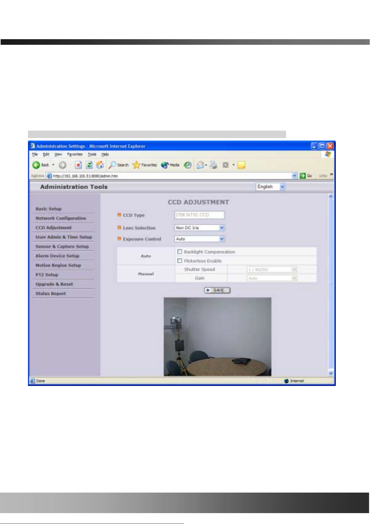
5.4. CCD Adjustment
You can optimize the quality of the video input by adjusting the parameter of the CCD. To enter
into this mode, click “CCD Adjustment” in the administrative page. You will find the screen
shown in Figure 5-5.
Click “SAVE” to save the parameter after you finish the parameter setting.
# CCD Type
Either NTSC or PAL type CCD sensors are installed on the NVC100/110. The type of CCD
is identified by the system and shown in this field.
# Lens Selection
Figure 5-5. CCD Adjustment
27
27 of
of 51
of of
51
5151
2727

NVC100/110 User’s Manual
Any lens having CS mount type can be installed on the NVC100/110. The standard
NVC100 is delivered with a C mount type fixed lens. In order for convenient replacement
with a CS type, a C-CS adaptor is packaged with the NVC100/110.
Confirm whether your lens is a Non DC IRIS or DC IRIS lens before your selection and
then click “SAVE” to save your selection.
DC IRIS Lens
Non DC IRIS
Lens
DC IRIS lens is a kind of auto IRIS lens. Opening of IRIS can be
adjusted by applying DC voltage. The opening of IRIS is optimally
adjusted by detecting the signal level from CCD. This type is
selected when CS Type DC IRIS (Auto Iris) lens is mounted on your
NVC100/110. DC IRIS has to be selected for NVC110.
Non DC IRIS lens is a fixed IRIS lens. This is a standard lens that is
installed with the NVC100. Non DC IRIS lens is factory default
selection for NVC100.
# Exposure Control
Users of the NVC100/110 can select either Auto or Manual exposure control. The sub
menus in Auto exposure mode are Backlight Compensation and Flickerless Enabled.
The sub menus in Manual exposure are Shutter Speed and Gain Adjustment.
Set the parameters to control the amount of light reaching the CCD sensor to obtain
various videos.
Adjusts the amount of light reaching the CCD automatically. If this mode is
selected, Backlight Compensation and Flickerless Enabled submenus are
activated. To apply to the sub menu, check the box at the left of each sub
menu and click “SAVE”.
□ Backlight Compensation
Auto
When the camera is acquiring video from an object with a bright
backlight, it is hard to identify the details of the targeting object since the
object appears very dark. Apply backlight compensation mode for this
case. Default mode is Backlight Compensation Off.
□ Flickerless Enable
When using the NTSC type NVC100/110 in a 50Hz AC regions or using
the PAL type NVC100/110 in a 60Hz AC region, video output tends to
flicker when the NVC100/110 is used under fluorescent lamps. This mode
28
28 of
of 51
of of
51
5151
2828

NVC100/110 User’s Manual
reduces the fl i ckerin g p hen omen a. If t hi s m ode i s s elect ed , th e elect ro ni c
shutter speed is set to 1/100 sec for the NTSC camera while it is set to
1/120 for the PAL camera to synchronize the shutter speed to the AC
current.
<Note> : Make sure that you apply this mode only when using an NTSC
camera in a PAL region or a PAL camera in a NTSC region.
Adjust the amount of light reaching the CCD manually. The Shutter Speed
and Gain sub menus are activated when this mode is selected. Check the
box at the left of each sub menu and click “SAVE” to apply the sub menu.
□ Shutter Speed
Electronic shutter speed can be selected between 1/60 sec and 1/10000
sec for the NTSC cam era. If using a PAL camera, shutter speed can be
Manual
selected between 1/50 sec and 1/10000 sec. If using a DC IRIS lens
under manual exposure mode, you will not find a difference in brightness
when controlling the shutter speed because the opening of the IRIS is
automatically adjusted. If using a NON DC IRIS lens, the brightness of
the video will change as you adjust the shutter speed. When using your
camera in low light conditions, set the value to a maximum (1/50 or
1/60) to increase the amount of light reaching CCD.
□ Gain
You can adjust the gain of CCD sensor in accordance with the speed of
the shutter. If you select Auto, the gain is automatically adjusted in
accordance with t he si tuat ion . Altern ati vely, you can select one of 10, 16,
22 or 28dB to set the maximum gain. Setting the gain to a higher value
will ensure you can enhance the brightness under low light conditions,
while it amplifying noise level.
29
29 of
of 51
of of
51
5151
2929

NVC100/110 User’s Manual
5.5. User Admin & Time Setup
You can change the ID and password of users and also assign different attributes for each user.
# User Administration
- Administrator
. Username: Admin ID. Default ID is “root”
. Password: Admin password. The default password is “dw2001”.
. Confirm Password: Enter the password once more to confirm the pas sword.
If you lost the Administrator’s ID and password, the only means of recovery is to reset the
settings to factory default, which will cause you to lose your previous set tings.
Figure 5-6. User Admin. & Time Setup
30
30 of
of 51
of of
51
5151
3030

NVC100/110 User’s Manual
- Add User
. Username: Enter the user ID you want to add. Up to 100 users are supported by the
NVC100/110.
. Password: Enter the user password.
. Attribute: You can set different system resource access capabilities for each of the
users.
Attributes are Audio, Bi-directional Audio, and Pan/Tilt.
For example, if you want a specified user to hear the audio from the
NVC100/110, check Audio in the check box.
- User List: You can list “user IDs” and “ their attributes” here.
Format: user ID[A, BA, P] : A – audio, B – bi-directional audio, P – ptz, attribute.
You can delete specific user by clicking the “DELETE” button.
# Authentication for Viewing: If you want to restrict viewing access to the NVC100/110,
check the “Yes” box and click on “Save”. Users need to input
their ID and password to connect to the NVC100/110 in viewing
mode. (Figure 5-7.)
Figure 5-7. User Authentication in NVC100/110
- If No, default attribute: If you uncheck the above “Yes”, every user can access the
Even if you have added a user through authentication for viewing connections to the
NVC100/110, it will not be enabled unless you check “Yes” in “Authentication for
Viewing” and click on the “Save” button.
NVC100/110 without restriction with the same attribute set
here. You can enable this by checking each attribute and
clicking the “Save” button.
# Time Setup
- Current Time: It shows you the current time of the NVC100/110.
31
31 of
of 51
of of
51
5151
3131

NVC100/110 User’s Manual
- Time Settings: You can set the time manually or you can synchronize the time to the PC.
Options Description
“Synchronize With Computer Time” Synchronize the time with the PC time.
“Set Manually” You can manually set the time.
5.6. Sensor & Capture Setup
This is the setup page for sensors and video capture conditions, which will be sent to user by FTP
or E-mail.
# Sensor Setup: A sensor can be connected to the NVC100/110.
Figure 5-8. Sensor & Capture Setup
32
32 of
of 51
of of
51
5151
3232

NVC100/110 User’s Manual
- Type Selection: Select sensor type . There are two types of sensors
. Normal Open: “floating” in normal situations, non-floating means an alarm condition.
. Normal Close: “non-floating” in normal situations, floating means an alarm condition.
# Vi deo Capture Condition: Sets the condition of the video recording and transmission via FTP or
E-mail. The NVC100/110 supports 3 types of conditions:
1. Sensor: When at least one of the sensors dete cts an alarm condition.
2. Motion-detected: When motion is detected from the video channel.
3. Periodic: Video is recorded during pre-defined time zone.
The above 3 condition s are mutually independent in opera tion.
# Sensor Select: Select the sensor that triggers video capture.
# Motion Detection Select: Select the video channel that trigger s video capture.
# Periodic Transfer Select: Set the pre-defined time for periodic video capture.
# Captured Video Transmission: Select a way of sending captured video. You can send
captured video through FTP or E-mail, or bo th.
- FTP is sent to the FTP Server. Refer to [Section 5.3.]
- E-mail is sent to the Recv E-mail address. Refer to [Section 5.3.]
If the FTP server is not properly assigned in Network Configuration mode, the
NVC100/110 ignores the video transmission by FTP
Captured video data for E-mail consists of intra frames only in consideration of the
limited storage space for E-mail account. FTP data contains entire video frames.
Video for periodic recording is sent only to the FTP server.
33
33 of
of 51
of of
51
5151
3333

NVC100/110 User’s Manual
5.7. Alarm Device Setup
Test alarm output and descr ibe the condition of alarm.
# Alarm Device Test: Test alarm devices. Press On/Off for testing.
# Alarm Device Active Condition: Set up the condition of the activating alarm device. Select
- Duration: Set the duration of the Alarm out.
10 sec, 30 sec, 1 min, 2 min, 5 min, 10 min, 30 min, 1 hour.
Figure 5-9. Alarm Output Setup
sensor or mo tion detection as the condition.
34
34 of
of 51
of of
51
5151
3434

NVC100/110 User’s Manual
5.8. Motion Region Setup
Set the motion detection regions. Up to 3 regions can be defined.
# Channel Selection: Choose the channel you want to enable motion detection.
- The NVC100/110 only has one channel (Channel 1).
# Channel Sensitivity: Set the sensitivity in motio n detection for each channel.
- 1 is the least sensitive number, and 66 is the most sensitive number.
- Sensitivity values can be set to be different among channels, but the same sensitivity is
applied for regions.
# Motion Region Setup: Set up the motion detection region with up to 3 per each video channel
Figure 5-10. Motion Region Setup
35
35 of
of 51
of of
51
5151
3535

NVC100/110 User’s Manual
- Region 1, 2, or 3: Motion detection is enabled for the c hannels by checking each box.
. You can set the region by pressing the “START” button, and clicking one corner of the
region in the left viewing area. It will show the coordinate value automatically. Next, press
the “END” button and click the other diagonal corner.
Regions are show n in three different transparent colors:
red (region 1), green (region 2), blue (region3)
“RESET” button clears the start & end point to (0,0) & (0,0)
. Percent: This value cont rols the sensitivity of ea ch region.
1 is the most sensitive and 100 is the least sensitive.
5.9. PTZ Setup
Set up and test the PTZ devices.
Figure 5-11. PTZ Setup
36
36 of
of 51
of of
51
5151
3636

NVC100/110 User’s Manual
# Channel Selection: Choose the channel having the PTZ device.
# PTZ Model Selection: Choose the PTZ model for each channel.
Different PTZ models can be applied for each channel.
- Delete Button: Press this button to delete the setup of the PTZ.
# PTZ Device ID : PTZ device can have ID, set PTZ ID here.
# PTZ Device ID: If yo ur PTZ device needs an ID, input the ID in this field.
# PTZ Operation Check: You can check the various operations of the PTZ devices.
Refer to [5.11 Upgrade & Reset] for adding a new PTZ device.
“Left”/”Right”/”UP”/”DOWN”, “AUTO FOCUS”/”ZIN”/”ZOUT”
“Left”/”Right”/”UP”/”DOWN”, “AUTO FOCUS”/”ZIN”/”ZOUT”
# PTZ Position Setup: You can set up the PTZ l imitation & preset positions if the PTZ device
supports it.
- Panning Limitation: Set the left/right limitation and test.
- Preset Position: Set the preset position and test.
<Note>: The “PTZ Position Setup” feature is applicable only for the PTZ devices that
support it.
37
37 of
of 51
of of
51
5151
3737

NVC100/110 User’s Manual
5.10. Encryption Setup
For additional securit y to th e video and aud io data tra nsm itted fr om the net work cam era, you can set k e y codes
and use them for encrypting the data from the network camera.
You can selectivel y activate encr yption for the video and aud io data. For e nabli ng the enc r yption, ch eck the box
at the left of the “Enable data encryption”, the n check the proper boxes to the left of “Video” and “Audio” . After
the selection, click on the SAVE button beneath the “Video” and “Audio” check boxes.
Figure 5-12. Upgrade & Reset
# Key Value: You can use up to 20 different key codes for the encryption of the data.
- Generation: To generate the key value, cl ick the “GENERATE” button. The boxes f or the Key valu es
will be filled with new values.
- Sav ing key values o n the Video server: Clic k the SAVE button beneath the GENERATE button to
save the key value generated by the network camera.
- Downloading key values t o your PC: The key values can be downloa ded and stored as a file to
your PC for reference when you make a connection. When encryption is enabled, the PC client
program will ask for a particular key value out of the 20 available key values.
38
38 of
of 51
of of
51
5151
3838

NVC100/110 User’s Manual
- Uploading key values t o the video server: The key value stor ed on your PC c an be uploaded to
your network c amera. This feature is useful when you m anage multiple network cameras having th e
same key value sets. Se lect a file having k e y valu es , t hen c l ic k the “INSTALL” button to upload the key
values.
39
39 of
of 51
of of
51
5151
3939

NVC100/110 User’s Manual
5.11. Upgrade & Reset
You can upgrade the NVC100/110 via the network.
For each of the upgrade of the system component, upgrade code should be downloaded from
Inscape Data’s home page before the s ystem upgrade is performed.
(Refer to [6.4. How To Upgrade Your NVC100/110 System]
# Automatic Upgrade
Automatic upgrade is a feature that enables the NVC100/110 to upgrade to newly released
system software by automatically connecting to Inscape Data’s upgrade server. The
administration page indicates a newer release by a blinking red arrow mark on the right of
Upgrade & Reset menu bar. Click Upgrade & Reset to enter into upgrade mode. You will
Figure 5-13. Upgrade & Reset
40
40 of
of 51
of of
51
5151
4040

NVC100/110 User’s Manual
find a screen as shown in Figure 5-12. Click the UPGRADE button to initiate the upgrade. All
the upgrade sequences will be perfor med auto matically.
#### Manual Upgrade
- System S/W Upgrade: Upgrade the system software installed in the server via the
network. System software needed for the upgrade can be downloaded from
Inscape Data’s home page. Refer to [6.4. How To Upgrade Your NVC100/110
System].
- Bootloader Upgrade: Upgrade the bootloader installed in the server via the network.
The bootload er needed for the up grade can be downl oaded from Inscape D ata’s
home page. Refer to [6.4. How To Upgrade Your NVC100/110 System].
- Add the PTZ File: A dd a new PTZ driver software via the network. The PTZ driver can
be downloaded from Inscape Data’s home page. Refer to [6.4. How To Upgrade
Your NVC100/110 System].
# Factory Default Setting: Re-initialize the NVC100/110 to the factory default state.
# System Reset: Perform a remote reset by clicking the “CONFIRM” button.
Once the NVC100/110 is re-initialized to the factory default state, it should be set up
again using the IP-Installer.
All previous connections will be disconnected upon reset. The NVC100/110 does not
resume the connections and the users must re-connect to the server manually.
41
41 of
of 51
of of
51
5151
4141
NVC100/110 User’s Manual
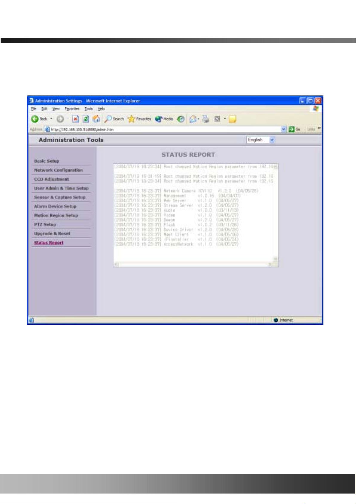
5.12. Status Report
Shows you system records since the system started.
You can check the problems as well as the versions and event status of the whole system and
each module.
Figure 5-13. Status Report
42
42 of
of 51
of of
51
5151
4242
NVC100/110 User’s Manual
6. Tips for Using the NVC100/110
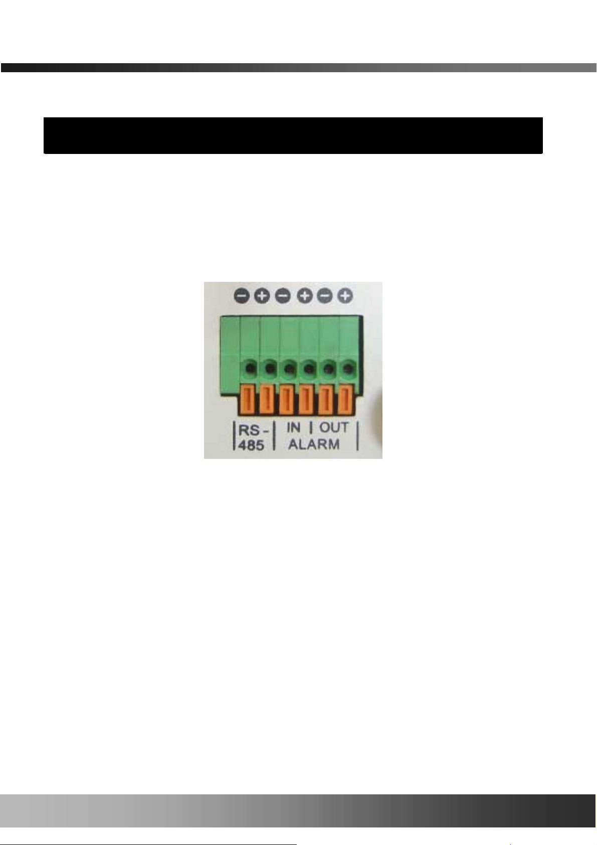
6.1. ALARM-IN and ALARM-OUT
ALARM connectors are used to connect various sensing and alerting devices. Examples of sensing
devices are infrared sensors, motion sensors, heat/smoke sensors, magnetic sensors, etc.
ALARM-OUT is used for connecting alerting devices such as loud speakers, flashing lights, etc.
1. ALARM-IN
Connect the two wires of the sensors. The sensor type can be set in Administrative
Mode (Ref. 5.5 & 5.6). Output lines providing on-off switching are connected between
the “+“ and “-” pins. Figure 6-2 shows the input circuit of “Alarm In”.
Figure 6-1. ALARM-IN/ALARM-OUT Connector
43
43 of
of 51
of of
51
5151
4343

NVC100/110 User’s Manual
2. ALARM-OUT
A Relay output is provided for connecting alarm devices or for remote on/off devices
such as light control. Relay circuits are normally open and circuits are closed upon
alarm output or remote on. The relay is capable of switching an AC/DC 30V,1A
electrical signal.
Figure 6-2. SENSOR input of NVC100/110
External Alarm Device
External Power
Figure 6-3. RELAY Output of NVC100/110
44
44 of
of 51
of of
51
5151
4444
NVC100/110 User’s Manual
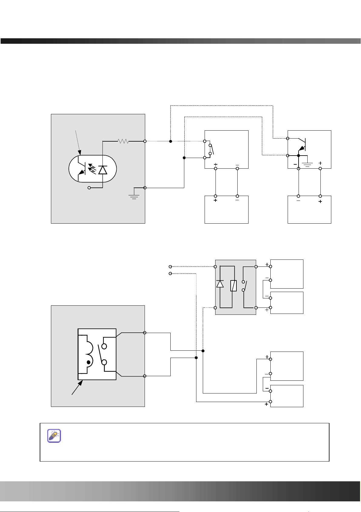
3. Connection of Sensor, Alarm Device
3.1 Connection of Sensor
Photo Coupler
GND
GND
+12V
+12V
+12V+12V
GNDGND
Sensor1+
Sensor1+
Sensor1+Sensor1+
Sensor1-
Sensor1-
Sensor1-Sensor1-
NO/NCType
NO/NCType
NO/NCTypeNO/NCType
Sensor
Sensor
SensorSensor
Device
Device
DeviceDevice
Sensor
Sensor
SensorSensor
Power
Power
PowerPower
Supply
Supply
SupplySupply
Open CollectorType
Open CollectorType
Open CollectorTypeOpen CollectorType
Sensor
Sensor
Sensor Sensor
Device
Device
Device Device
Sensor
Sensor
SensorSensor
Power
Power
PowerPower
Supply
Supply
SupplySupply
3.2 Connection of Relay
Relay Switch Power Supply
1V~30VDC /AC,1A
1V~30VDC /AC,1A
1V~30VDC /AC,1A1V~30VDC /AC,1A
Alarm
Alarm
AlarmAlarm
Out
Out
OutOut
Device
Device
DeviceDevice
Power
Power
PowerPower
Supply(
Supply(30V
Supply(Supply(
~)
Optional
Relay Switch
Alarm
Alarm
AlarmAlarm
Out
Out
OutOut
Device
Device
DeviceDevice
Power
Power
PowerPower
Supply
Supply
((((1111~30
SupplySupply
VDC/AC,1A ))))
Relay
Relay1
----
++++
Relay1
You can use the supported relay output to directly drive a maximum load of
30V AC/DC at 1A. By connecting additional relay circuitry (such as an optional relay
switch), it can also drive heavier loads.
45
45 of
of 51
of of
51
5151
4545

NVC100/110 User’s Manual
6.2. Trouble Shooting
1. After the NVC100/110 is successfully installed.
• When the NVC100/110 is in viewing mode, neither channel name nor video is
displayed, and eventually a timeout message is shown.
Check the power and networ k connection of the NVC100/110.
To check if the network is properly operating, open the browser and try to connect to
any server.
Example) http://www.yahoo.com
Or open the MS-DOS Prompt and type the following.
ping www.yahoo.com
Then press Ente r. If you see the “ Rep ly f rom …” message it means that the network is
working properly. To check if the NVC100/110 is connected, open the MS-DOS Prompt
and type the following.
ping [the IP of the server]
Example) ping 192.168.1.112
If you see the “Reply from …” message, it means that the server is properly connected.
If you do not see a Reply message, check if the network cable and power cable are
properly connected.
• The name of the channel on the NVC100/110 is displayed but there is no video.
Check if there is input video source to the channel. And check if there is a firewall in the
network. Check if the network is NAT type.
In case there is a firewall in the network:
1. Try a TCP connection. A TCP connection is usually enabled by checking the TCP box
before connecting to the NVC100/110. Refer to the viewer manual for more detailed
operation.
2. TCP causes delay and low network throughput. It is recommended you use UDP
connection for better performance. To use the UDP c onnection, UDP ports from 6970 to
7009 should be open. Ask you network manage r for assistance.
If the network is NAT type, you need port mapping. This can be achieved by setting the NAT
46
46 of
of 51
of of
51
5151
4646

NVC100/110 User’s Manual
server to forward all packets coming in through a specific port to the NVC100/110. You must
open the UDP Ports from 6970 to 7009.
2. After Successfully Connecting to the NVC100/110
• Video movement is slow.
In the Basic Setup of Admin Mode, lower the “Quality”. High quality means more data. You
can also set the “Max. Bandwidth” to a higher value. However, this value must be lower than
the maximum upload speed of your network. For example, if the maximum uploading
bandwidth of the network is 400Kbps, set the total “Max. Bandwidth” to 384Kbps. If you set it
higher, th e video image can be corrupted with artifacts. Ask your network manager or ISP for
the maximum uploading bandwidth of the network.
• The image is dull and I see green and pink dots.
This could be caused by perfo rmance limitations of the PC. Do not run too many programs
while running the viewer program. The other reason could be missing data while transmitting
from the NVC100/110.
•••• Mosaic phenomenon.
Mosaic phenomenon occurs when not enough network bandwidth is available considering the
resolution and frame rate of the video.
An example is 640x240 video with low Max. Bandwidth.
Users are recommended to adjust resolution and frame rates to lower values for lower
bandwidth network.
47
47 of
of 51
4747
of of
51
5151

NVC100/110 User’s Manual
6.3. Web Viewer
The NVC100/110 is designed to be connected through Internet Explorer, too. For connecting to
the NVC100/110 using Internet Explorer, type in the IP address or host address in the address
input field of the Internet Explorer field.
Figure 6-4. Web Viewer of NVC100/110
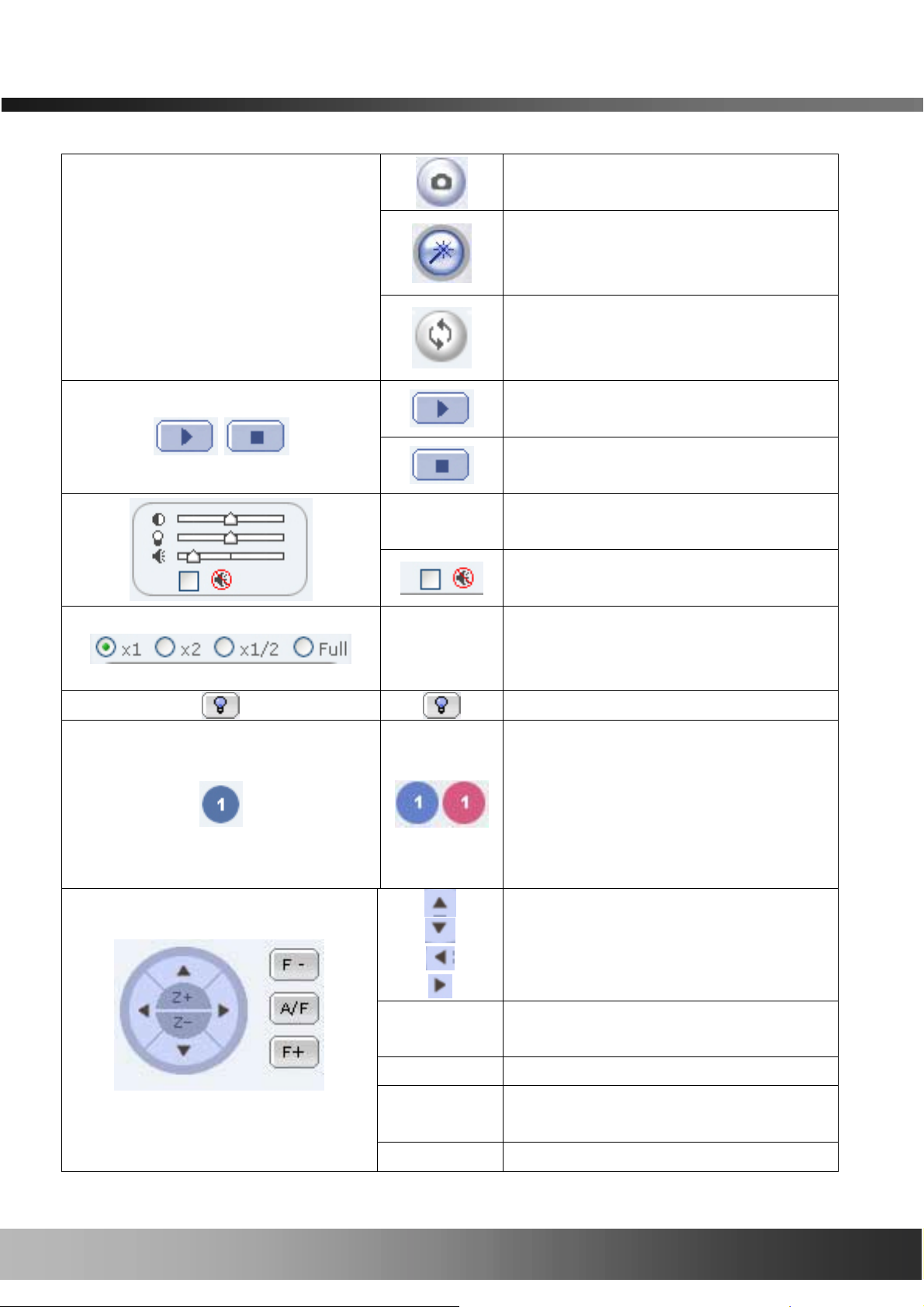
! Control Panel of Web Viewer
48
48 of
of 51
4848
of of
51
5151
Enable bidirectional audio. When
bidirectional audio is enabled, audio
from your PC is delivered to the
NVC100/110.
NVC100/110 User’s Manual
Capture and store the still image on
your desktop screen.
Connect to the NVC100/110 in
administrative mode of the
NVC100/110.
Rotate the screen by 180 degree.
Connect to NVC100/110.
Stop the connection.
Contrast, Brightness, and Volume
adjustment.
Check the box to mute the audio.
Adjust the size of the screen. Normal
Z+
Z-
F- Moves the focus to a farther position.
A/F
(x1), Twice (x2), Half (1/2), Full Screen
(full).
On/off the relay by pre ssing the button
Shows the status of the sensor. A blue
color means that the sensor is in a
normal state, whil e a red col or indicat es
an alarm situation.
The number on the button indicates the
number of the sensor.
Move the center of the camera in
up/down/left/right directions.
Zoom in (Z+)
Zoom out (Z-)
Auto focus.
F+ Moves the focus to a nearer position.
49
49 of
of 51
of of
51
5151
4949

NVC100/110 User’s Manual
6.4. How To Upgrade Your NVC100/110 System
There are two ways of upgrading the system software of the NVC100/110. In most cases it is
more convenient to upgrade the system software in automatic sequence. But when your
NVC100/110 cannot be connected to our upgrade server, it is recommended you use a manual
upgrade.
1. Automatic Upgrade
1) Connect to the NVC100/110 and log on to administrative mode with administrator’s ID and
Password. Then start “Upgrade & Reset” menu.
2) When your system software is older than the latest release, the admin page will indicate
this fact with a blinking red arrow mark on the right of the “Upgrade & Reset” menu.
Click the “Upgrade & Reset” menu when the indicator is blinking. You will find a screen
as shown in Figure 5-12. Click the “UPGRADE” button to start the upgrade.
3) The server will notify the en d of the u pgrade process on your screen.
4) Click the Confirm button to the right of System Reset to re boot the NVC100/110.
5) After the reboot is finished, log on to the NVC100/110 with administrator ID and password.
Then click the “Status Report” menu to display the current status of the NVC100/110.
6) Confirm the version number and date of all the system software on your NVC100/110.
2. Manual Upgrade
1) Save the upgraded system software to your PC. Upgrade software can be downloaded from
50
50 of
of 51
of of
51
5151
5050

NVC100/110 User’s Manual
Inscape Data’s home page or provided in CD.
2) Log on to administrative mode and select the “Update & Reset” menu.
3) Click "Browse..." to find the files you want to use for the upgrade. This will open a "Choose
file" dialogue window. The file extension is “ief”.
4) When you've found the file, click "Open." This will select the file and close the "Choose file"
dialogue window.
5) Click the "INSTALL" button. An alert message box will pop up. Click the “OK” button so it
will start uploading the file. This may take some time.
6) An upgrade completion message will appear after the system upgrade h as been completed.
7) Reboot the NVC100/110 by performing a “System Reset”.
8) After rebooting, log on to the server in administrative mode again and click the “Status
Report”.
9) Check the version number and release date of the NVC100/110.
You can download the NVC100/110 system software from Inscape Data’s homepage-
http://www.InscapeData.com.
51
51 of
of 51
of of
51
5151
5151
 Loading...