

Page 1

LP7510
Weighing indicator
USER MANUAL
Edition:2012-03-19
Page 2
Safety Instruction
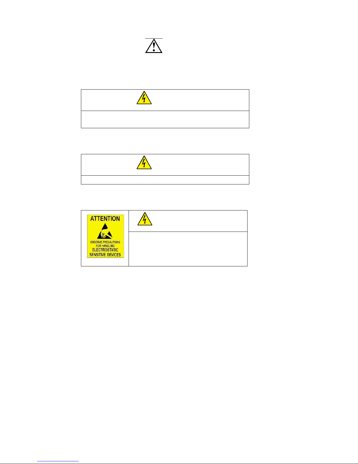
For safety operation pls. follow the safety instruction.
WARNING
Setting. Calibration Inspection and Maintain of the indicator is
prohibited by Non-professional staff.
WARNING
Pls. make sure the weighing display have good ground in using
WARNING
The indicator is the static and sensitive equipment,
cut off the power during electrical connections,
internal components touched by hand is prohibited,
and please take the measure of anti-static.
Page 3

LIST
1. Instruction .......................................................................................................... 1
1.1 Main function ........................................................................................... 1
1.2 technical parameter ............................................................................... 1
1.3 Outline(mm) ..................................................................................... 2
1.4 Battery instruction .................................................................................... 2
2.Installation and calibration .................................................................................. 3
2.1 Power supply connection ......................................................................... 3
2.2 Connection of load cell and indicator ....................................................... 3
2.3 Communication interface ......................................................................... 4
2.4 4-20mA output ......................................................................................... 5
3. Basic operation ................................................................................................... 9
3.1 keypad ...................................................................................................... 9
3.2 Power on & off ....................................................................................... 11
3.3 Zero operation ........................................................................................ 11
3.4 T are operation ......................................................................................... 12
3.5 Accumulation operation ......................................................................... 12
3.6 Print ........................................................................................................ 13
3.7 Hold ........................................................................................................ 13
3.8 COUNT .................................................................................................. 13
4. Calibration and Parameter setting .................................................................... 14
4.1 Enter setting ........................................................................................... 14
4.2. Step of calibration operation ................................................................. 15
4.3 Application function parameters setting chart ........................................ 17
5. Output format ................................................................................................... 22
5.1 Second display continuous sending format ............................................ 22
5.2 Computer continuous sending format .................................................... 23
5.3 Serial interface reception command: ................................................... 23
5.4 Print format ............................................................................................ 24
5.5 PC or Second display continuous sending format .................................. 25
6. Maintenance ..................................................................................................... 26
6.1 Regular error and solution ...................................................................... 26
6.2 Daily maintain ........................................................................................ 27
6.3 Restore default parameter ....................................................................... 27
6.4 Packing list ............................................................................................. 29
Page 4

1
1. Instruction
This weighing indicator is designed for bench scale, floor scale, the basic
weighing function include: Hold, Print, kg/lb conversion. Optional: I/O, 4-20mA
output.
1.1 Main function
Weighing function:
Zero, tare, accumulation. printing, animal weighing.
kg/lb convert. Overload remind.
Print format: Date, Time, Net,Tare,Gross
Options:
Pinter
RS232/RS485
I/O
4-20mA
1.2 technical parameter
Accuracy class 5000 e
Resolution display: 30, 000 ADC: 2,000,000
Zero stability error TK
0
< 0.1μV//K
Span stability error TK
spn
< ± 6 ppm//K
Sensitivity (internal) 0. 3 μV /d
Input voltage -30~30mV DC
Excitation circuit 5 VDC, 4 wire connection,
Maximum connect 6 load cell of 350Ω
AC power AC100~250V
Operation temperature - 10 °C ~ + 40 °C
Operation humidity ≤90%RH
Storage temperature - 40 °C ~ + 70 °C
Page 5
2
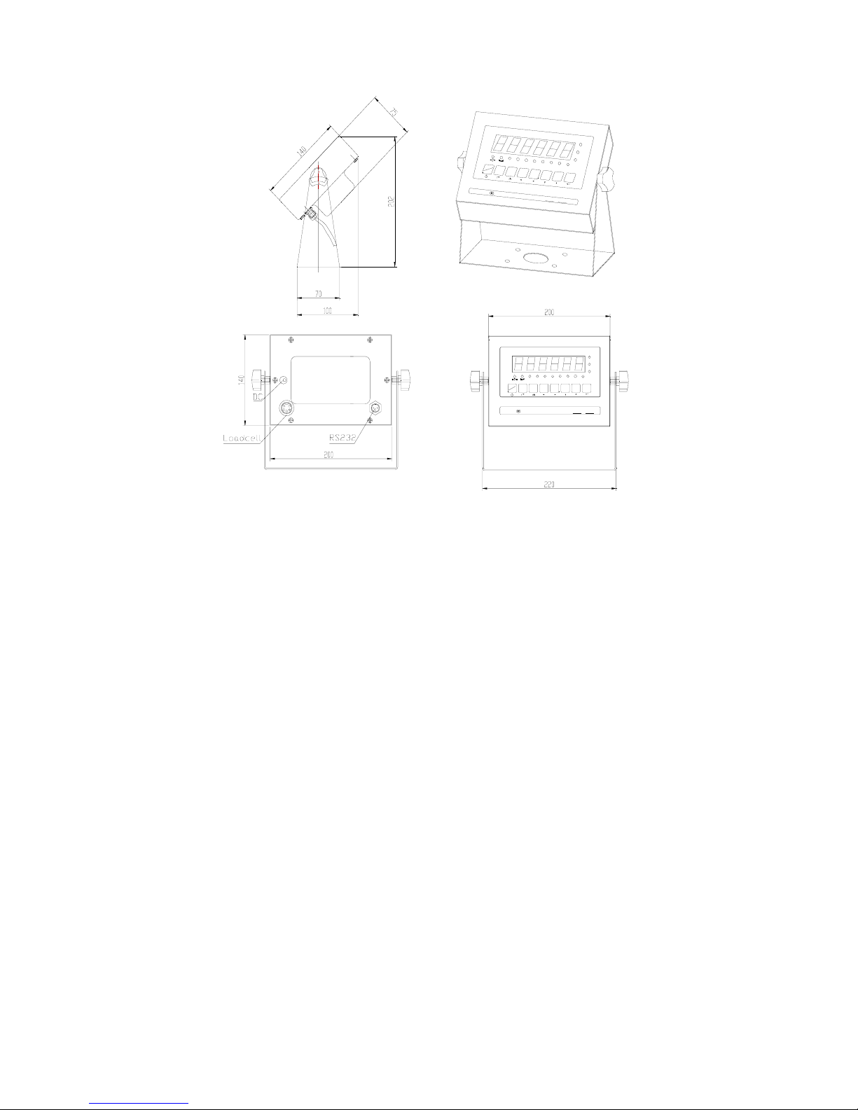
1.3 Outline(mm)
L
O
C
O
S
C
LP7510 Weighing Indicator
Hi
ok
Lo
Gross Net Tared Total Hold pcs kg Battery
ON
OFF
Total Gount
Gross
Tare Zero Print
Class Capacity=
d=
kg/lb
L
P
7
5
1
0
W
e
i
g
h
i
n
g
I
n
d
i
c
a
t
o
r
H
i
o
k
L
o
G
r
o
s
s
N
e
t
T
a
r
e
d
T
o
t
a
l
H
o
l
d
p
c
s
k
g
B
a
t
t
e
r
y
O
N
O
F
F
T
o
t
a
l
G
o
u
n
t
G
r
o
s
s
T
a
r
e
Z
e
r
o
P
r
i
n
t
k
g
/
l
b
C
l
a
s
s
C
a
p
a
c
i
t
y
=
d
=
1.4 Battery instruction
1. when you use the internal battery first time,you should charge
the battery fully, to prevent low voltage resulted from self leakage
of battery.
2. when the “red” light flash means low battery, pls. charge it in
time
3. the light turns to red during charging
4. when the light turns to green, means fully charged.
5. if battery is not used for long time, take it out to avoid the
leakage.
6. In order to keep the battery in best using condition, it is suggest
Page 6
3
that you fully discharge the battery every month, the method is that
using the indicator till it is automatically power off.
2.Installation and calibration
2.1 Power supply connection
The indicator is powered by adapter, you plug the adapter directly into
the “DC” pin at the back cover the indicator is ok.
2.2 Connection of load cell and indicator
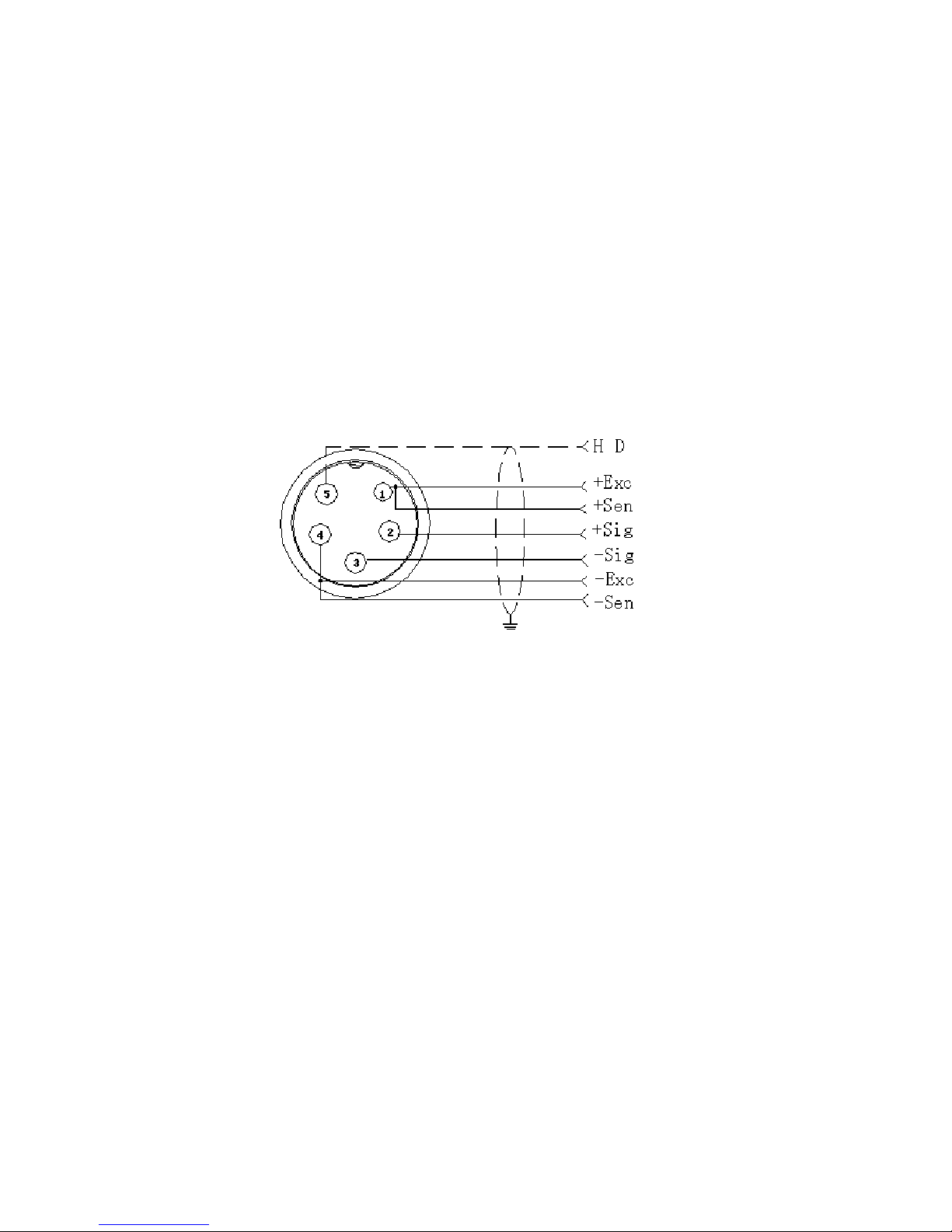
The indicator can connect with 6 load cell of 350Ω at most, 4 wire or 6
wire load cell both ok.
There are two methods connection between load cell and indicator
A. quick disconnect, as below:
B. Terminal trip connection (inner connection)
1. the exciting voltage for the load cell is 5VDC, the largest output
current 120mA, maximum connect 6 pcs 350Ω load cell;
2. Load cell (or the signal cable for the junction box) is connected
with 5 bit
Terminal trip ( SENSOR) on the circuit-board of weighing indicator.
Page 7
4
3. Open Weighing indicator back cover, insert signal cable to the
terminal trip(SENSOR), and make sure the screw is fixed tightly, the
connection as below:
Weighing display Load cell
+EXC + voltage
+SIG + output signal
HD ----------- Shielded
wire
- SIG - output signal
+EXC+SIG HD - SIG -EXC -EXC - voltage
2.3 Communication interface
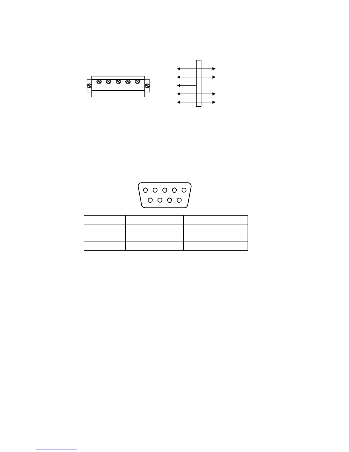
RS232 : DB9 Pin or 3 Pin
DB9 definition
5 4 3 2 1
9 8 7 6
Pin function and definition as bellows:
DB9 joint Definition Function
2 TXD Sending data
3 RXD Receiving data
5 GND Ground interface
Note: if RS485, The connection pin is 2 and 5 pin.
Page 8
5
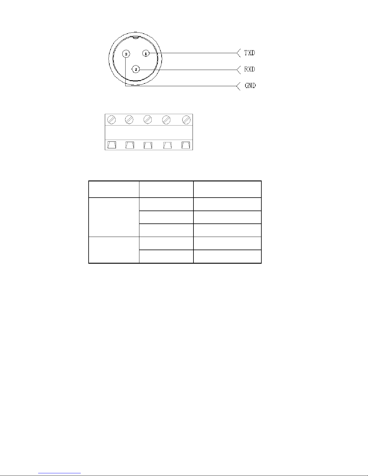
3 Pin definition
Inner connection
TXD RXD GND A B
Pin definitions:
Pins Definitions Function
RS232
TXD Sending data
RXD Receiving data
GND Ground
RS485
A RS485 output “A”port
B RS485 output”B”port
2.4 4-20mA output
Technical parameters:
Resolutions: 1/1000
Outside Load:
100-350Ω
Connection:
Page 9
6
1. Inside connection: 4-20mA, load input port connect with “I” of J602, Ground
port connect with “ GND” of J602
2. Outside connection: 4-20mA, load input port connect with “1” pin of DB9,
Ground port connect with “6” pin of DB9
Testing :
Connect the 250Ω to the 4-20mA, adjust the multimeter to the current stalls, the
red pan connect the loading port, and the black pan connect” GND” to test the
output current.
Calibration:
1. Press” Print” and “ Total” go to C32, show[out-4], the output current should be
4mA.
2. If Press [↑]show[out-5],Pres[↓]show[out-20],the output current should be
20mA.
3. Adjust the current, for example, adjust to [out-20], Press [←](“Zero”
key)or[→](Net/gross key)to adjust the current
Function instruction:
4~20mA correspond to Zero ~Max. capacity. After press” TARE”, the weight will
start from 4mA. SET C31=0, 0~20mA output mode.; C31=1 4~20mA output mode.
If you need 0~5V output, Set C31=0, Then connect 250Ω at the two ends of
current output., will get 5voltage at resistance two ends
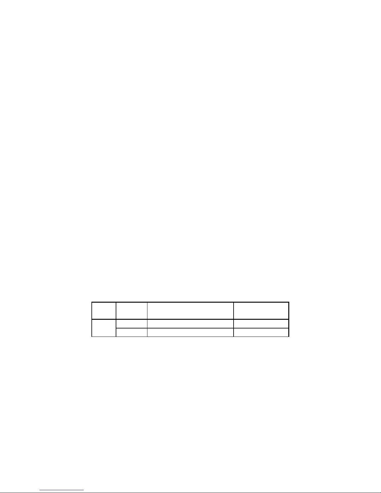
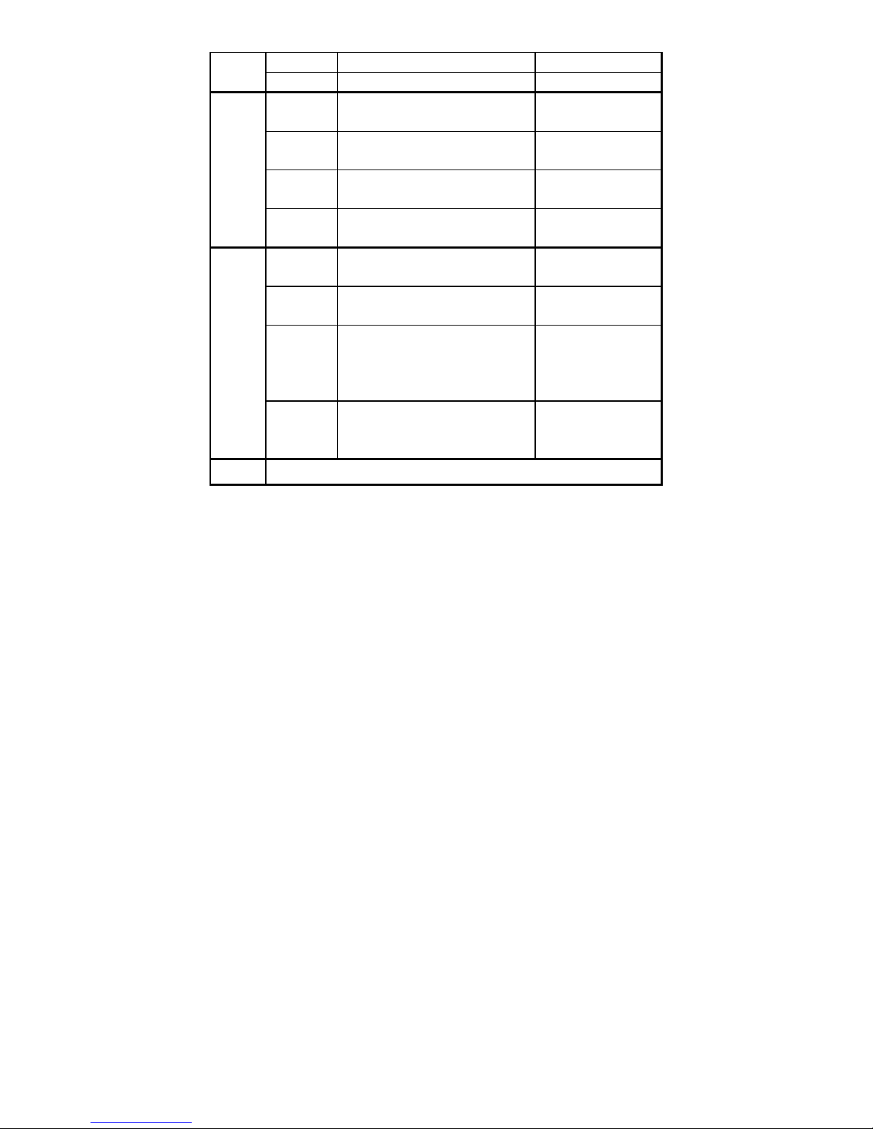
Relay output signal function
The indicator can output 4 signal , connect with the outside equipment
the indicator can perform automatic control function and upper limit
and lower limit alarm function. Perform the 4 kinds function through
setting C33, 4 signals
As below
Output
port
Port definition Function
C33=0
Out1 Close output function No output signal
Out2 Close output function No output signal
Page 10
7
Out3 Close output function No output signal
Out4 Close output function No output signal
C33=1
Out1 Open overload control function Output overload
control signal
Out2 Open compliance control function Output compliance
control signal
Out3 Open underload control function Output underload
control signal
Out4 Open stable control function Output stable control
signal
C33=2
Out1 Weight>=C13 instant connection Feeding control
signal
Out2 Weight<=C14 instant connection Feeding control
signal
Out3 OUT1、OUT2 close When OUT1、OUT2
connect will output
alarm signal,
connect with buzzer
Out4 Weight<=C14 constant
connection
Weight>=C13 disconnect
Feeding start and
stop
C33=3 Preserved, no function.
For example:
Check weigher application. Connect indicator with yellow, green, red 3
lights. Yellow light on when overload, if ok the green light on. If
underload red light on. And can connect with buzzer. There would be
alarm remind when overload.
C33=2 Feeding control application
For hopper scales. The target is between is 50~500kg, the Output
card can perform open and close feeding valve.
Parameter setting C13=500kg C14=50kg
C13=500kg upper limit , close feeding valve
C14=50kg lower limit, open feeding valve.
Page 11
8
Connection: 1. Connect directly control machine, pls. connect OUT 4,
suggest connect another manually switch as the stop switch in
emergency
2. indicator output signal will influence the ON/OFF switch to control
machine, OUT 2 ON, OUT 1 OFF, OUT 3 connect buzzer, alarm
remind when start and stop.
Instruction: when the weight over 500kg, OUT 1 OU3 instant
connection and break off, OUT 4 break off; when weight under
50kg, OUT 2 OUT3 instant connection and break off, OUT 4
constant connection
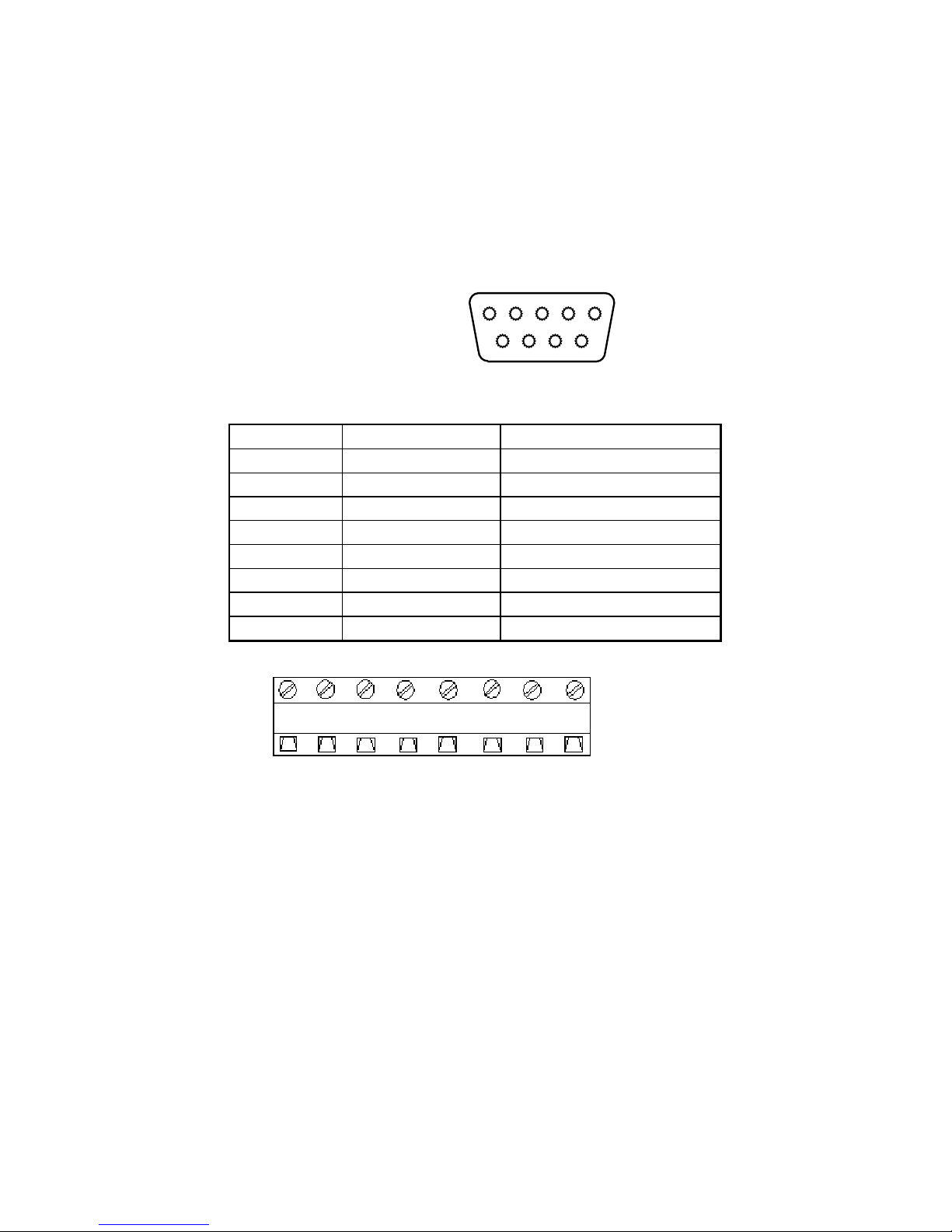
5 4 3 2 1
9 8 7 6
DB9 pin definition port
1 pin 1st output signal pin Out1
6 pin 1st output signal pin Out1
2 pin 2nd output signal pin Out2
7 pin 2nd output signal pin Out2
3 pin 3rd output signal pin Out3
8 pin 3rd output signal pin Out3
4 pin 4th output signal pin Out4
9 pin 4th output signal pin Out4
Inner connection pin definitions
1A 1B 2A 2B 3A 3B 4A 4B
Page 12
9
3. Basic operation
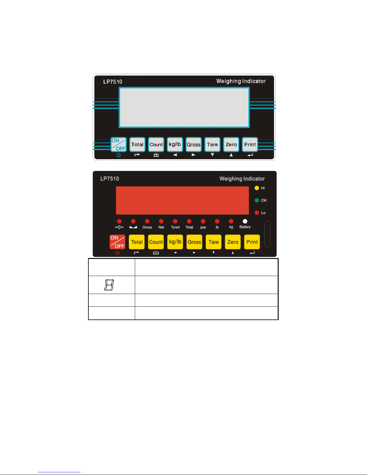
3.1 keypad
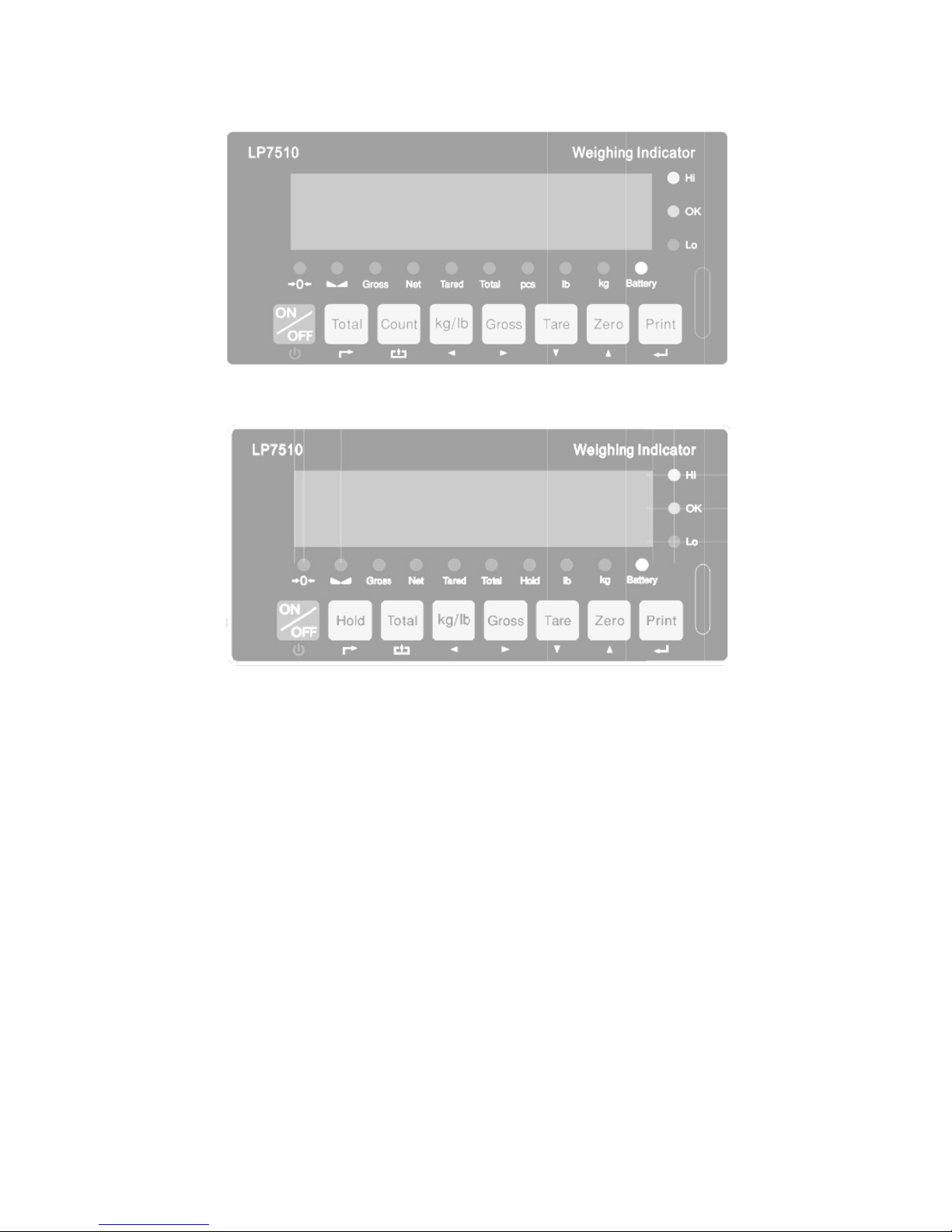
LED instruction
Weighing data
kg
kg
lb
lb
Page 13
10
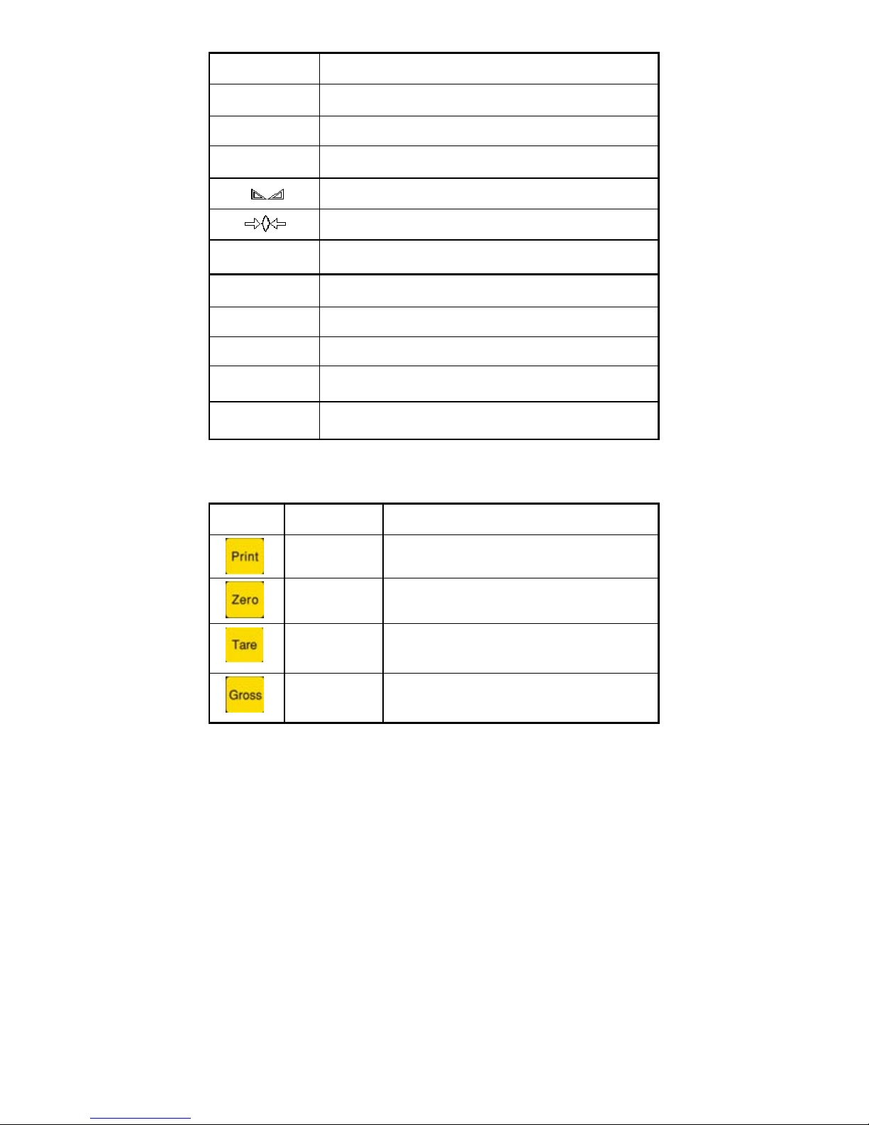
Hold
Data hold
Gross
Gross weight
Net
Net weight
Tare
tare
The weighing data is stable
Weight is zero
Hi
Overload
OK
ok
Lo
Underload
.
Decimal
PCS
Show the counting status.
TOTAL
Go to accumulation mode
Keys function
keys Key name Key function
Print
Print
Zero
Zero the weight within tolerance
Ta re
At G.W mode, get the tare weight. At N.W
mode, clear the tare, get the G.W
Gross weight
At N.W mode, check the G.W, after 3
seconds back to N.W automatically
Page 14
11
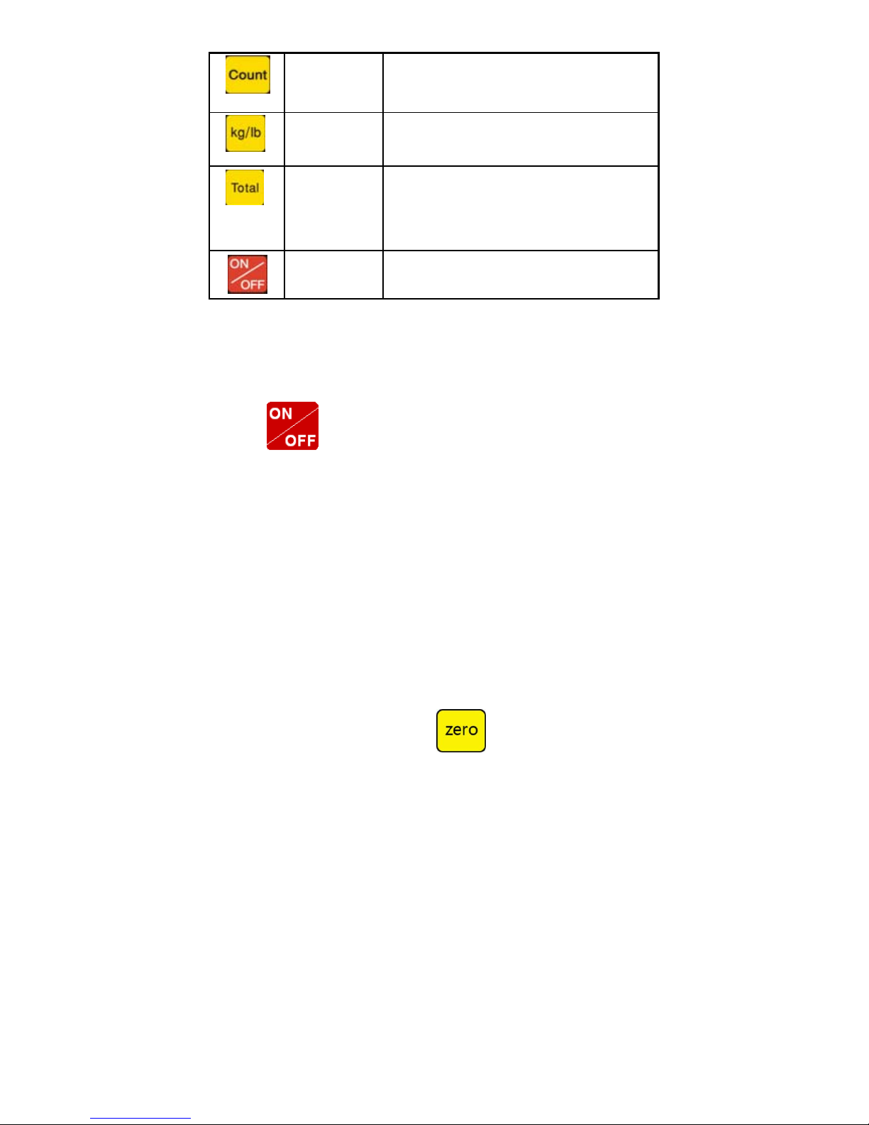
Counting
Counting operation
Kg/lb convert Covert between kg and lb
Accumulation
1. Accumulation
2. work together with “ Print” to perform
The accumulation function and check the
accumulation result
Power on/off
Press 2 seconds to power on or power off
3.2 Power on & off
Press 2 seconds to power on or power off, after power on the
indicator show”000000-999999”. After self inspection. It go to the weighing
mode. Pls. check it whether 6 bits LED/LCD display and the status light is
good or not.
3.3 Zero operation
1. Initial zero setting
When power on the indicator, if the weight on the scale is within the
initial zero tolerance, indicator show zero automatically.
2. Manually Zero setting
When the scales is stable, and not the negative display, you can zero
the weight within tolerance by press
keys.
Page 15
12
3.4 Tare operation
Press “TARE” key, the gross weight is tared, indicator show the Net
weight, the “Net” “tared” status light is on. At tare mode, Press” TARE”
key, clear the tare weight, the indicator will show the gross weight.
3.5 Accumulation operation
At Zero mode, load weight till stable, Press go to accumulation
mode, ”Total” light on, display” n 001”, and then display loaded weight; unload
the weight , back to zero, load the second weight again till stable. Press
display”n002” then display the second loaded weight. Repeat it agin
and again, maximum 999 times.
Check the accumulation
Press “ON/OFF “key and hold it then press “TOTAL”” key, display ”n**”, (it is
the accumulating times) then show total weight. there are 8 digits totally. It
shows the first 4 digits then the last 4 digits. For example, the first 4 digits
is”0012”, the last 4 digits is”34,56” It means the actual weight is “1234.56”
EXIT the accumulation function
When the indicator show the last 4 digits, Press hold it, the
indicator show “ clr n”, it means don’t clear the total Weight, Press “PRINT”
key to exit it; if you want to clear total weight, Press “ZERO” or “TARE” key,
“clrn” change to “clry” it means clear total weight ,then Press “PRINT” to clear
the total weight and exit accumulating mode.
Page 16

13
3.6 Print
If the weighing is stable, after connect with printer, press” PRINT”
can print the weight. Note: at tare mode, print with tare. if negative
weight,, can not print. Set C30 for time format.
3.7 Hold
There are two different hold function. Peak hold function and data hold
function. And the setting is different accordingly.
C11=3 Automatic hold function C11=0 close hold function.
3.8 COUNT
1.At weighing mode, load the weights on the platform scales, Press”
Count” the indicator show” PCS 0” press” Zero” key input the quantity,
press” Print” to confirm it
2 . Load the goods on the platform scales, then the indicator will show
the quantity.
3. Press” Count” back to weighing mode.
4. If you want to weigh different goods, at weighing mode, put the
sample on the platform scales, press” Count” the indicator show”0”
Press “ Count” hold it and then press “ ON/OFF” the indicator show”
PCS 0”, press “Zero” input the sample quantity, press “ Print” to
confirm it. Then repeat the step 2 and 3.
Page 17

14
4. Calibration and Parameter
setting
4.1 Enter setting
There have two methods to enter the setting menu:
1. Put the switch “MARK” to “On” position, enter calibration
And when calibration is finish. Put the switch “ MARK” to “off” position.
Then add the sealing screw at the back of indicator.
2. when the switch “ MARK” is on position, press the “ ” hold it
and then press” ” enter calibration.
The key functions in setting:
ENTER
UP
DOWN
LEFT
RIGHT
BACK
EXITCALIBRATION
POWER
Page 18
15
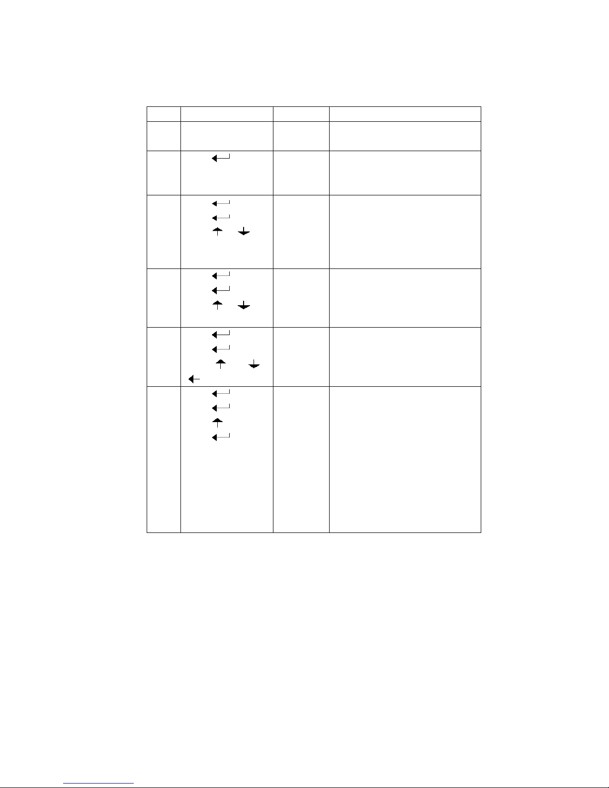
4.2. Step of calibration operation
According to the second method which can enter setting menu,
C01-C39
step
Method of operation
display Remark
1 [C01 ] After you enter calibration mode,
it display [C01 ]
2 press [C01 1] Weight unit
option:1=kg
2=lb
3 press
press
press or
[C02 ]
[C02 0]
[C02 2]
Set decimal digits
option:0/1/2/3/4
Select decimal digit
example:two decimal point :
[C02 2]
4 press
press
press or
[C03 ]
[C03 1]
[C03 5]
Set graduation
option:1/2/5/10/20/50
Select required graduation
example:graduation 5:[C03 5]
5 press
press
press or /
[C04 ]
[0100.00]
[0100.00]
Max capacity
example:max weighing 100kg:
[0100.00]
6
press
press
press
press
[C05 ]
[C05 0]
[C05 1]
[CAL 9]
。。。。。。
[0000.00]
Zero calibration
Option
0=no need zero calibration
1=need zero calibration
calibration zero please choose 1 and
ensure scale is empty and “stable”
light is on
Ensure zero calibration, countdown.
Till show[0.00](example for two
decimal point)。
Page 19
16
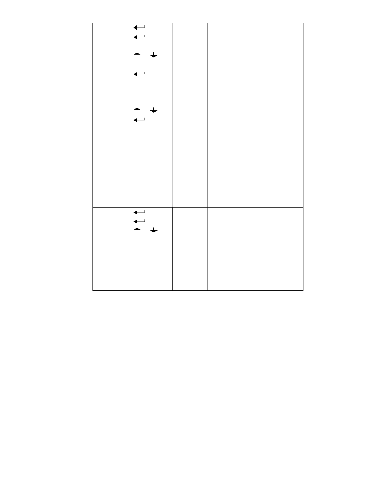
7 press
press
press or
press
press or
press
[C06 ]
[C06 0]
[C06 1]
[SPAN ]
[0100.00]
[0080.00]
[CAL 9]
……
[0080.00]
[CAL End]
calibration
option:
0=No need calibration
1= need calibration
Load weights on scales
according to max. capacity.
Suggest close to the max
capacity, at least 10% of max.
capacity.
For example: the weights is
80kg
As bellows:
Input the 0080.00, count down ,
then indicator shows 0080.00 ,
calibration is over.
If you want to set application
function parameter. Press
“PRINT” if you want to exit
press “COUNT”
8
press
press
press or
[C07 ]
[07 0]
[07 1]
Default parameters setting
option:0=non-restore default
parameters
1=restore default parameters
Note: after the above
parameters setting finish, please
do not set default parameters to
avoid the original setting
parameters is lost.
Page 20

17
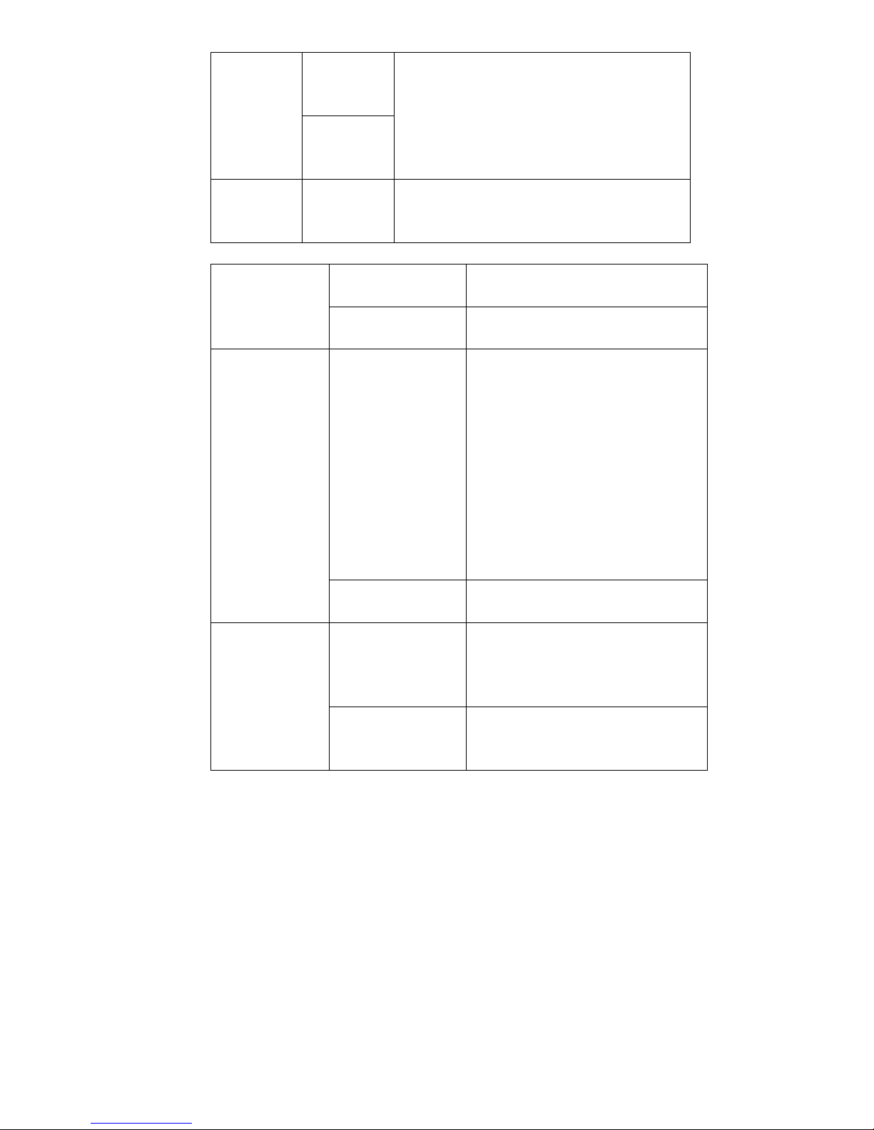
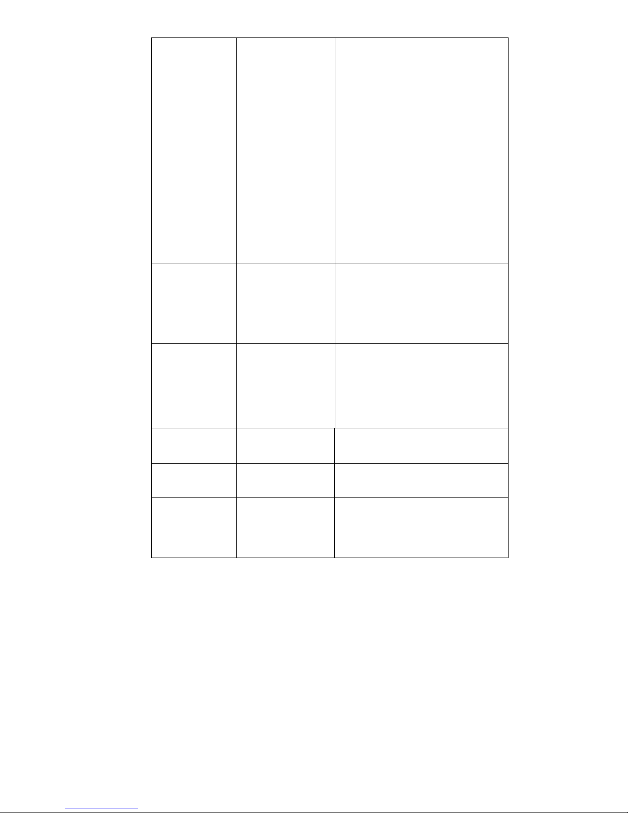
4.3 Application function parameters setting chart
Function
Setting
Item
parameters setting and instruction
warning
tone
C08
warning
tone
Options: 0 = close warning tone
1 = open warning tone
Automatic
power off
C09
Automatic
power off
option:0=close auto power off
10= power off automatically if no
change within 10 minute.
30= power off automatically if no
change within 30 minute.
60= power off automatically if no
change within 60 minute.
Power saving
setting
C10
Power saving
setting
LED Version:
option:0= close power saving setting
3= close display if no change within 3min.
5= close display if no change within 5 min.
LCD Version:
0=Close he backlight
1= backlight when the weight change or
press the keyboard
2=constant backlight
Hold
function
C11
Hold mode
option:0=close hold function
1=Peak hold /2=Data Hold
Instruction:
Peak-hold: it shows the maximum. data,
mainly application for materials testing,
such as tension and pulling force.
Date-hold: it shows current weight value.
Mainly application for animal weighing.
Kg/lb
conversion
C12
Kg/lb
conversion
C12=0 stop kg/lb conversion
C12=1 kg/lb conversion is ok
Page 21
18
Upper/lower
limit alarm
C13
Upper limit
alarm value
You can set it within the max. capacity limit
C14
Lower limit
alarm value
Inner Code
display
C15
Check inner
code
enter C15 to check the inner code
Date and time
C16
Date
Enter C16, you can set the date,
from left to right: year/month/day
C17
Time
Enter C17, you can set the time from
left to right: hour/min./sec.
Communication
setting
C18
Serial interface
data output method
option:0= Close serial interface data
output
1=Continuous sending, connect
second display
2=Print method, connect printer.
3=Command request method ,
connect computer.
4=PC continues sending format,
connect computer.
5=PC/ second display continuous
sending format.
C19
Baud rate
option:
0=1200/1=2400/2=4800/3=9600
Zero range
C20
Manually zero
range
Option:
0= close manually zero setting
1=±1% max capacity
2=±2% max capacity
C21
Initial zero range
option:0= no initial zero setting
1=±1% max capacity
2=±2% max capacity
Page 22

19
5=±5% max capacity
10=±10% max capacity
Zero tracking
C22
Automatically zero
tracking range
Options:
0= close zero tracking
0.5=±0.5d
1.0=±1.0d
2.0=±2.0d
3.0=±3.0d
4.0=±4.0d
5.0=±5.0d
Note: 1. d = division
2. the zero tracking range can
not bigger than manual zero range.
C23
Automatically zero
tracking time
Options:
0= close zero tracking time
1= 1 second
2= 2 seconds
3= 3 seconds
Overload range
C24
Overload range
option: 00= close overload range
01d~99d
remark:d =division
Negative display
C25
Negative display
range
Option:0=-20d
10=10% max. capacity
20=20% max. capacity
50=50% max. capacity
100=100% max. capacity
Standstill time
C26
Standstill time
Option:
0= quick 1= medium 2= slow
C27
Standstill range
Option:
1= 1d 2=2d 5=5d 10=10d
D= division
Page 23
20
Digital filter
C28
Dynamic filter
Instruction :
Dynamic filter is
collecting the data
filter before loaded
weight stable.
When loaded
weight easily
shaking (for
example animal) ,
you can set this
filter to make
weight display
more stable
option:0= close dynamic filter
1=1 digital filter strength
2=2 digital filter strength
3=3 digital filter strength
4=4 digital filter strength
5=5 digital filter strength
6=6 digital filter strength
Note : Pls setting dynamic filter
strength carefully, the No. is
bigger, more stable. if the
loaded weight shake not too
much. The setting is less than 3
C29
Noise filter
option:0=close noise filter
1=1 digital filter strength
2=2 digital filter strength
3=3 digital filter strength
C30
Print time and date
C30=0 yy.mm.dd
C30=1 mm.dd.yy
C30=2 dd.mm.yy
C30=3 yy.mm.dd
Analog output
setting
C31 output type C31=0 0~20mA output
C31=1 4~20mA output
4~20mA current
calibrate
C32 calibrate
current
Refer to 2.5
Relay output
setting
C33 Relay output C33=0 close relay output
C33=1 Open relay output function 1
C3=2 Open relay output function2
C33=3 Preserved menu
Page 24
21
Muti
communication
add.
C34
Communication
add.
C34= 0~99 Add. Code
Wireless
communication
C35 C35=0~99 signal
Gravity of
calibration
location
C36 C36=9.7000~9.9999
Gravity of
destination
C37 C37=9.7000~9.9999
Version No. C38
Preserved menu C39
Print mode C41 C41=0 auto mode
C41=1 gross mode
C41=2 tare mode
See 5.4 Print format parts in detail
Print carriage
return
C42 C42=0~9
Space Print C43 C43=0~9
Date Print C44 C44=0 not print date
C44=1 print date
Time Print C45 C45=0 not print time
C45=1 print time
Page 25
22
5. Output format
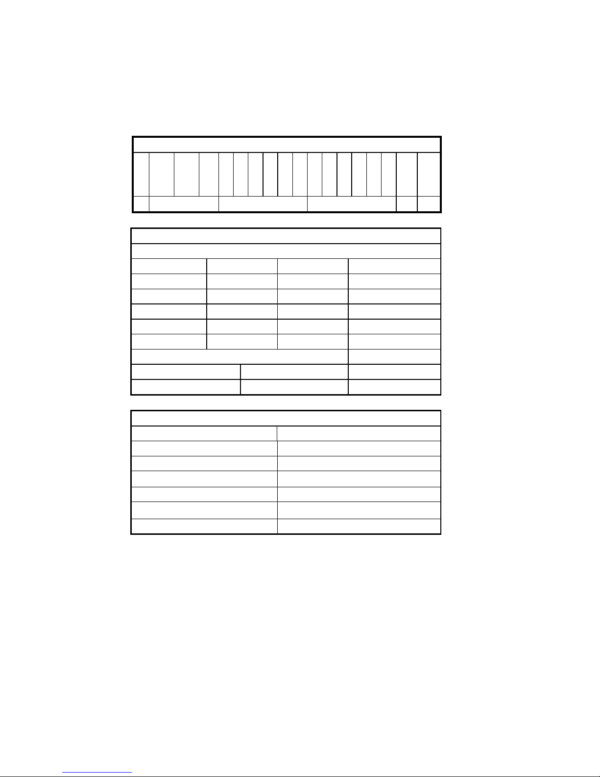
5.1 Second display continuous sending format
Output continuous format
S
T
X
S
W
A
S
W
B
S
W C X X XXXXXXXXXX
C
R
C
K
S
1 2 3 4 5 6
State A
Bits0,1,2
0 1 2 Decimal point position
1 0 0 XXXXXX0
0 1 0 XXXXXXX
1 1 0
XXXXX.X
0 0 1
XXXX.XX
1 0 1
XXX.XXX
Bits3,4 Division
0 1 X1
1 0 X2
State B
BitsS function
Bits0 gross=0, net=1
Bits1 Symbol: positive =0,negative =1
Bits2 Overload(or under zero)=1
Bits3 dynamic=1
Bits4
unit:lb=0, kg=1
Bits5 Constant 1
Page 26
23
Bits6 Constant 0
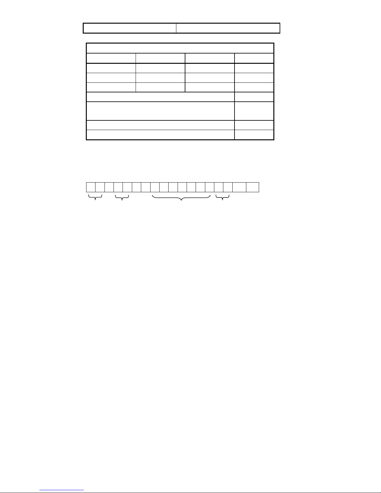
State C
Bit2 Bit1 Bit0 unit
0 0 0 Kg or lb
0 0 1 g
0 1 0 t
Bit 3 printing=1
Bit 4
Extend
display=1
Bit 5 Constant 1
Bit 6 Constant 0
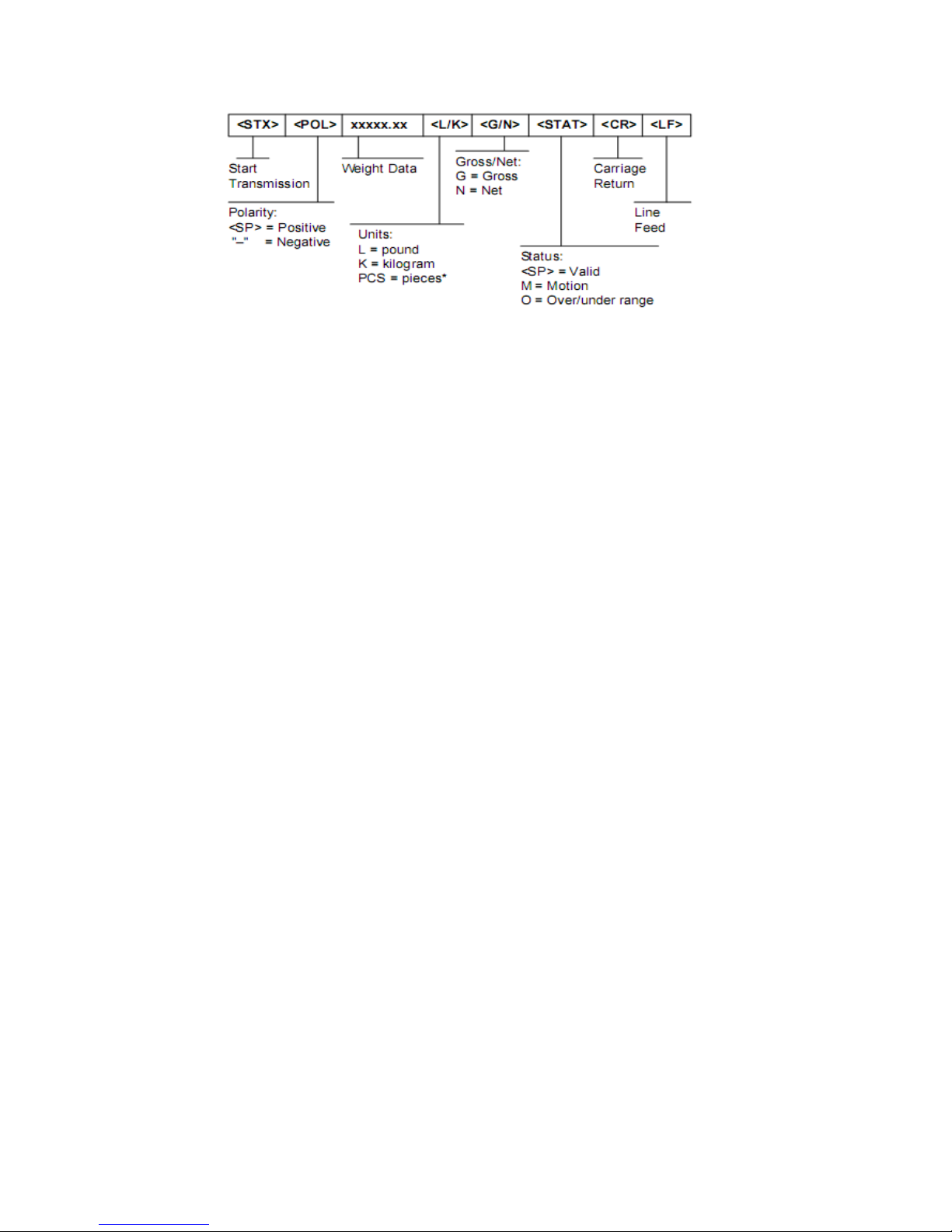
5.2 Computer continuous sending format
, ,
CR LF
S 1 S 2 S 3 Data
S 4
S1: weight status, ST= standstill, US= not standstill, OL= overload
S2: weight mode, GS=gross mode, NT=net mode
S3: weight of positive and negative, “+” or ” –“
S4: “kg” or “lb”
Data: weight value, including decimal point
CR:
carriage return
LF: line feed
5.3 Serial interface reception command:
RS232COM serial interface can receive simple ASCII command.
Page 27
24
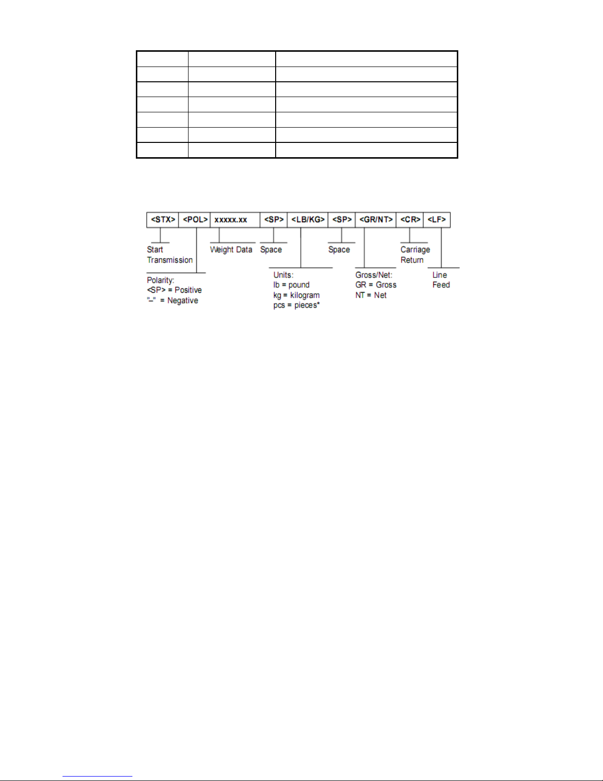
Command word and role as follows:
Command NAME Function
T TARE Save and clear tare
Z ZERO Zero gross weight
P PRINT Print the weight
R G.W/N.W Read gross weight or net weight
C Kg/lb Kg/lb conversion
G G.W Check gross weight at net weight mode
R command receive data format
5.4 Print format
Tare mode:
Date: XX.XX. XX
Time: XX:XX:XX
NET XX.X kg
TARE XX.X kg
GROSS XXX.X kg
Gross mode:
Date: XX.XX. XX
Time: XX:XX:XX
GROSS XXX.X kg
Page 28
25
5.5 PC or Second display continuous sending format
Page 29
26
6. Maintenance
6.1 Regular error and solution
ERROR REASON SOLUTION
UUUUUU
1. Overload
2. wrong connection
with load cell
3. load cell has quality
problem.
1. reduce the weight
2. check load cell connection
3. inspection load cell. Check
the input and output
nnnnnnn
1. calibration is no good
2. wrong connection
3. load cell has quality
problem
1. check scale is resisted or
not, foot is kept level or not.
2. check load cell connection.
3. checking load cell
ERR1
not input the weights or
the weight is overload
Input the correct weights
ERR2
During calibration , the
weights is below than
Min. required weights
The calibration weights
Minimum is 10% of Max. cap.
Recommend 60%-80% of Max.
Cap.
ERR3
During calibration, the
input signal is negative
1. check the connection is
correct
2. check load cell is no
problem
ERR4
During calibration, the
signal is unstable
After the platform is stable,
start calibration
ERR5 Change PCB
Page 30
27
ERR6 Exceed zero range Remove the load
6.2 Daily maintain
1. Protect the indicator from strong sunlight to prolong the using life
2. Good connection between load cell and indicator. Far from away
from strong electric field, magnetic field.
3. Power off the indicator when lightning
4. Power off the indicator firstly before plug and unplug
6.3 Restore default parameter
Enter to calibration, Set C07=1. Press” ” then press” ” to exit
saving setting. All parameter will back to default
Note: Pls. do not restore default parameter easily if you are not
professional staff or not yet calibrate the scales.
Default parameter
Parameter instruction Default
C01
Calibration
1
C02
Decimal digits
0
C03
Resolution
1
C04
Max. capacity
10000
C05
Empty calibration
0
C06
Capacity calibration
0
C07
Restore default
0
C08
Warning tone
1
C09
Power-off automatically
0
C10
Power saving mode
0
Page 31
28
C11
Hold function
0
C12 Prohibit kg/lb conversion
1
C13 Upper limit alarm 000000
C14 Under limit alarm 000000
C15 Inner code
C16 Date setting
C17 Time setting
C18 Serial interface data output 0
C19 Serial interface Baud rate
3(9600)
C20 Zero manually 10
C21 Initial zero 10
C22 Zero tracking range
0.5
C23 Zero tracking time 1
C24 Overload range 9
C25 Negative range 10
C26 Standstill time 1
C27 Standstill range 2
C28 Dynamic filter 0
C29 Noisy filter 2
C30 Print format 0
C31 Analog signal options 1
C32 4~20mA testing 4
C33 Relay output setting 1
C34 Muti PC communication add. 0
C35
Wireless communication channel
6
C36 Calibration location gravity 9.7936
C37 Destination gravity 9.7936
C38 Version No. check
C39 Reserved menu
Page 32
29
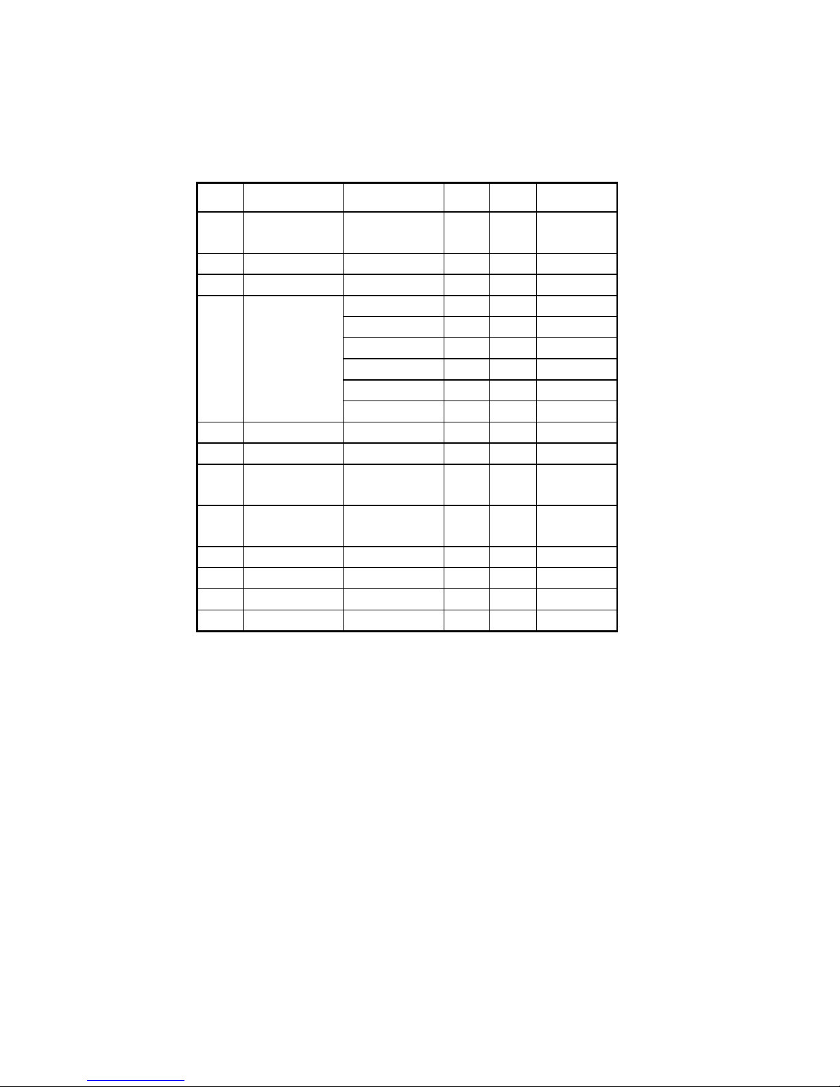
6.4 Packing list
Packing list
S/N ITEM NAME UNIT QTY PACKING
1
Weighing
indicator
PCS 1
2 Plastic bag PCS 1
3 bag PCS 1
4 Adapter
China/DC9V PCS
1
US/DC9V PCS 1
UK/DC/9V PCS 1
EU/DC9V PCS 1
AU/DC9V PCS 1
OTHERS PCS 1
5 USER MANUAL PCS 1
6 RS232 3 PIN OR DB9 PCS 1
7
LOADCELL
PLUG
5 PIN Quick
disconnect
PCS
1
8
Signal cable Φ5/3 core shield
signal cable
PCS
1
9 Power cable 3 coreΦ0.75mm PCS 1
10 Bracket Wall-mounted PCS 1
11 Certificate PCS 1
12 Packing list PCS 1
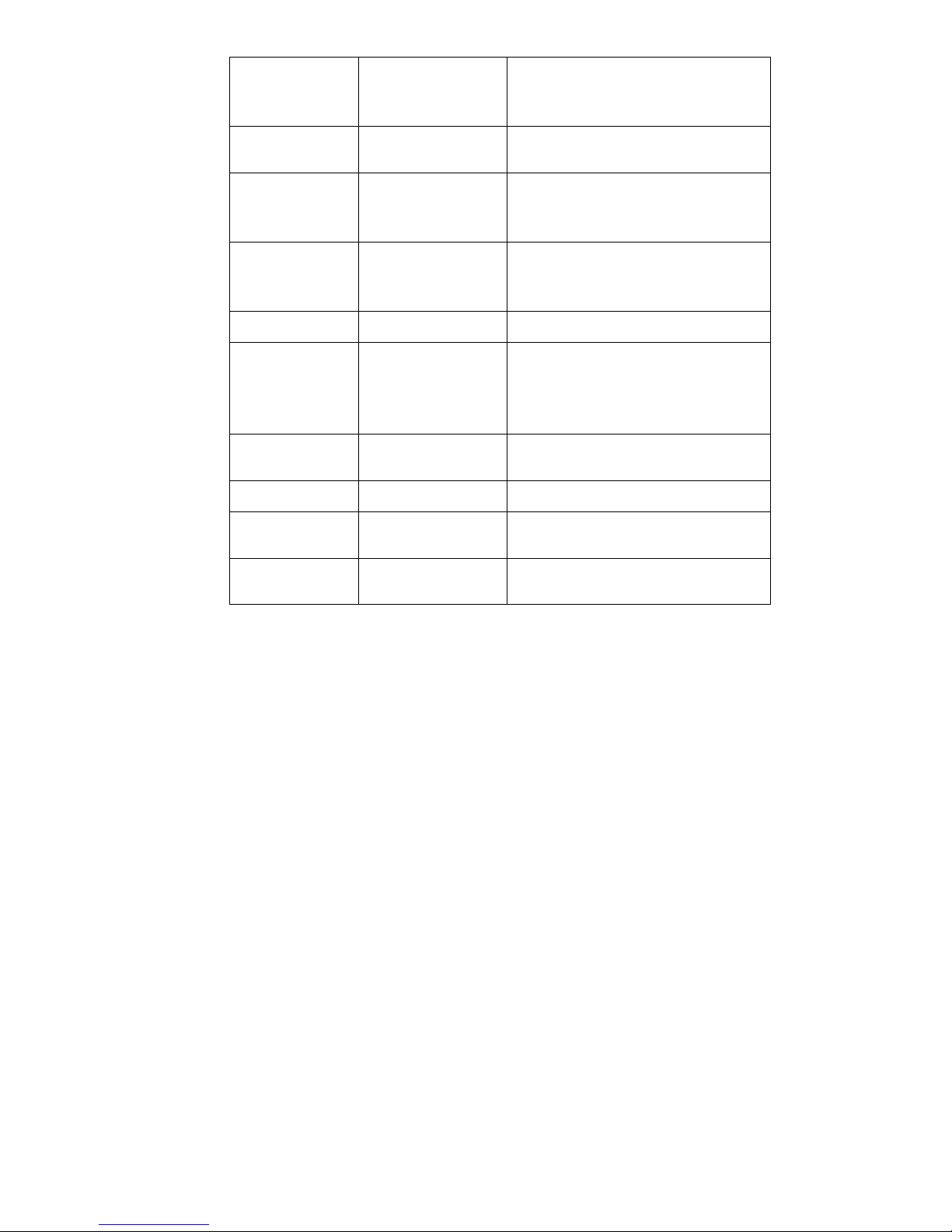
Page 33
30
 Loading...