


PUMA
SUBSOILER
INSTRUCTIONS MANUAL
PUMA H

01
01 - Introduction
- Warranty certifi cate
02 - Parts:
- Subsoiler Puma
- Subsoiler Puma H
03 - Safety Rules
- Transport over truck
04 - Technical features:
05 - Assembly
- Assembly of ground wheel on the frame
- Wheel Assembly
- Rear roller Assembly
- Coulter Blade assembly
- Hydraulic system assembly
- Drawbar assembly
- Shanks assembly
06 - Hitch:
- Hitching the Subsoiler in the tractor
- Puma H Hitch Procedure
- Puma H Alignment Procedure
- Puma H Leveling Procedure
07 - Adjustment and operations:
- Depth Adjustment for Subsoiler Puma
- Depth Adjustment for Subsoiler Puma H
- Pressure Adjustment in auto-return Device
- Spacing between shanks Puma H
- Coulter Blade adjustment
- Rear Roller Subsoiler Puma
- Operations
08 - Maintenance:
- Lubrication
- Operations maintenance - Problems During the Subsoilers Works
- Operations maintenance - Problems With Hydráulics System
- Lubrication point
- Tyres infl ations
- Subsoiler transport
10 - Clear procedure
11 - Spare parts
12 - Identifi cation
TABLE OF CONTENT
2
3
4
5
6 - 7
8
9
10
10
10
11
11
12
12
13 - 14
15
15
16
16
17
17
18
18
19
19
20
21
21
22
23
24
25
25
26
26
26

02
INTRODUCTION
This manual is an important part of your machine provided by INRODA
Indústria de Roçadeiras Desbravador Avaré Ltda and should remain with
the machine when you sell it.
Reading your operator’s manual will help you and others avoid personal
injury or damage to the machine. Information given in this manual will provide the operator with the safest and most effective use of the machine.
Knowing how to operate this machine safely and correctly will allow you to
train others who may operate this machine.
The dealer will delivery the equipments and explain about safe working,
maintenance technical support and provide further details about the terms
and conditions of the warranty.
To obtain performance of the warranty, the original purchaser must request warranty service from a distributor authorized to sell the product to
be serviced .
Following the instructions of this manual and correct maintenance it will
provide a long years of trouble-free from your implement.

03
WARRANTY CERTIFICATE
INRODA Indústria de Roçadeiras Desbravador Avaré Ltda., as manufacturer warrants all parts, (except those referred to below), of the product
described in this manual to be free from defects in materials and workmanship during the period of 6 (six) month from the invoice date to the first
purchaser following the rules bellow :
WARRANTY COVER
The warranty will cover defective parts not subject to normal wear and tear will be repaired or replaced at our option during the warranty period
when the use follow the content of this manual.
To requesting the warranty is necessary show the warranty certificate and invoice with all fields filled in observance of the warranty rules.
WARRANTY VOID CONDITIONS
This warranty does not apply to equipment or parts that have been subjected to improper or unauthorized installation or alteration and modification, misuse, negligence, accident, overloading, overspeeding, improper maintenance, repair or storage so as, in our judgment, to adversely affect its
performance and reliability;
Failure to follow recommended operating and maintenance procedures, including maintenance in dealer unauthorized by the manufacturer, also
voids warranty
Maintenance and replacement of parts by not genuine INRODA parts;
Project changes also void the warranty;
Incomplete or incorrect filling of the warranty certificate.
THE WARRANTY DOES NOT COVER:
Damages caused by accidents;
Part damaged by the normal wear unless problems from defects in materials and workmanship.
Fluids and lubricate oil;
Transportation charges on product submitted for repair or replacement under this warranty must be borne by purchaser.
GENERAL CONDITIONS
All equipment and parts replaced under this warranty will become the property of the manufacturer, INRODA;
The warranty of parts replaced are limited of the equipment warranty period above described.
Delay in warranty services does not provide right to reimbursement, indemnification or extending the warranty

04
01 - Complete auto-return shank
02 - Complete Wheel
03 - Complete wheel articulation support
04 - Frame
05 - Hydraulic hose support
06 - Hydraulic hoses
07 - Rear roller bearing
08 - Drawbar adjuster
09 - Drawbar hitch device
10 - Rear roller
11 - Complete coulter blade
12 - Attachment rear roller support
13 - Hydraulic cylinder
14 - Rear roller oscillation bar
02 - PARTS
13
14
07
05
12
08
DRAWING 01
09
06
09
04
14
01
02
03
11
10
SUBSOILER PUMA

05
01 - Frame
02 - Complete Shank
03 - Depth control wheels
02 - PARTS
02
01
03
SUBSOILER PUMA H
DRAWING 02

06
03 - SAFETY RULES
THIS IS THE SAFETY ALERT SYMBOL. IT IS USED TO ALERT YOU TO POTENTIAL PERSONAL INJURY HAZARDS.
OBEY ALL SAFETY MESSAGES THAT FOLLOW THIS SYMBOL TO AVOID POSSIBLE INJURY OR DEATH.
1 - Do not keep bystanders, child near of the working area during the operations or over the implement.
2 - Do not turn on the tractor engine in closed place without appropriate ventilation because the gas is bad for health.
3 - Before coupling or uncoupling the hydraulic hoses relief the pressure
4 - Inspect periodically the hydraulic hoses and replace when fi nd any wear or damage, the oil work in high pressure and any damages may result in
serious injuries or death.
5 - Do not any adjustment when tractor is turned on
6 - During the tractor moving by roads pay attention in brake controls and use the safety devices
7 - Before performing any services in the discs gangs wear gloves.
8 - While maneuvering the tractor to hitch the implement be sure that there is enough space and nobody is too close, maneuver always in slow gear
and be ready to brake in case of emergency.
9 - Do not use large clothes because they can get caught on the implement.
10 - Drive the tractor always at safe speeds, especially when working in irregular or inclined lands, keep the tractor always geared.
11 - When working over hilly land try to keep the necessary stability. In case of instability reduce the acceleration, turn the wheels to the inclined side of
the land and never lift the implement.

07
12 - When you start the tractor engine, be correctly placed at the operators seat and be aware of the correct and safe handling of both tractor and implement. Always place the gearshift crank at the neutral position, turn off the gear of the power command and place the hydraulic commands at the neutral
position.
13 - Do not work with the tractor front’s too light in order to avoiding this problem use the extra-weights
14 - When you leave the tractor set the gear in neutral position and use the parking break. Never leaves the tractor with the hydraulic system raised.
WARNING: The incorrect handing of this implement may result in serious injuries or death. Before using the implement read carefully the instruction manual. Be sure that the person responsible for the operation is instructed about the correct handing and safety and has understood
the instruction manual concerning this machine.

08
TRANSPORT OVER TRUCK
The transport in long distances must be done by a truck or another vehicle able to doing it, following the instructions
below:
- For loading and unload the hoist use proper ramps Do not use hilly places it may result in serious injuries
or death.
- For unloading the hoist use proper anchor points .
- Lock the hoist on the vehicle during the transport.
- Use the proper devices (rope, chain, wire) to attaching the hoist during the transport procedures
- Inspect the hoist after 8km then check ropes and attachment devices every 100km traveled
- Pay attention about the transport height because electrical power lines overhead or in bridges may result
in serious injuries or death..
- Inform about local laws height and width requirements when necessary follow the regulations for lighting
requirements be sure turn signal lights and tail lights are clean and visible.

09
TABLE 01
Model Number
of shank
Working
Width
Spacing between
shanks (mm)
Weight Working depth
(mm)
Tractor
required (CV)
Work
speed
PUMA 3000 H 3 930
310
456
450
45 - 65
4 a 8 km/h
PUMA 5000 H 5 1550 642 60 - 80
PUMA 7000 H 7 2170 860 80 - 105
PUMA 9000 H 9 2790 1039 100 - 130
04 - TECHNICAL FEATURES
TABLE 02
Model Number
of shank
Working
Width
Disc
Diameter
Spacing between
shanks (mm)
Spacing betw
shanks
Working depth
(mm)
Tractor
required (CV)
Work
speed
PUMA 5000 5 1875
18” 375
1552
450
100 - 125
4 a 8 km/h
PUMA 7000 7 2625 2186 140 - 175
PUMA 9000 9 3357 2569 180 - 225
PUMA 11000 11 4125 3098 220 - 275
PUMA 13000 13 4875 3538 260 - 325

10
To inspecting the parts in the packet wear gloves and to moving the parts
from the packet use proper procedures.
05 - ASSEMBLY
ASSEMBLE OF GROUND WHEEL ON THE FRAME
WHEEL ASSEMBLY
To assemble the ground wheel on the frame follow the instructios below:
Install the bearing (1) in the wheel (2) using the bolts (3) then use the bolt
in the frame (4) locking with the washer (5) and nuts (6).
Install the hydraulic cylinder (7) between the frame (4) and wheel (2) using
the pins and cotter pins (8) follow the right position illustrated in the drawing
03.
DRAWING 03
Install the complete ground wheel (1) in the implement housing (2), then
attach using the nuts (3).
03
06
05
01
02
04
08
07
08
DRAWING 04
01
02
03

11
COULTER BLADE ASSEMBLY
Couple the coulter blade bearing (1) in the frame (2) using the bracket (3),
install the bolt (4) by the items (1) and (3) locking with the washer and nuts
(5) then install the coulter blade support (06) in the bearing, reaching the
best position for the working lock using the bolt and nut (7).
DRAWING 06
REAR ROLLER ASSEMBLY
To assembling the rear roller follow the instructions below:
When you fi nish the procedure to assemble the shank in the frame, couple
the support (1) on the frame (2) using the brackets (3) then put the bolt (1)
in the items (1) and (3) locking with the nuts and washers (5) as illustrated
in the drawing 5.
Then install the spring rod (6) in supports (1) locking with the cotter pin
(7), install the bar (8) in the support (1) coupling the spring rod (6) in the
bar (8) locking with the pin (9) and cotter-pin (10). Moreover install in the
spring rod the bushing (11), the spring (12) lock with the nuts (13), install in
DRAWING 05
the rear roller (14) the metal sheet (15) and couple the bar (08) using the
washer and nuts (16).
13
11
13
12
11
08
16
15
04
07
01
09
03
05
02
14
06
10
04
05
07
03
02
01
06

12
DRAWBAR ASSEMBLY
DRAWING 08
Joint the drawbar (1) in the frame (2) lock with the pin and lynch pin (3)
install the three point device (4) in the items (1) and (2) lock with the lynch
pin (5) then install the adjustment nut (6) and the hoses supports (7) as
illustrated in the drawing 8.
07
03
01
06
04
05
02
05
Attach the connector support (1) in the frame couple the hoses (2) from
the connectors support (1) to the hydraulic cylinder (3), the hoses from
the connectors support to hydraulic cylinder (5) and the hoses to (6) the
remote control. Then attach the hoses (4) using the supports (7) washer
and bolts (8).
DRAWING 07
08
08
07
02
04
01
05
03
06
07
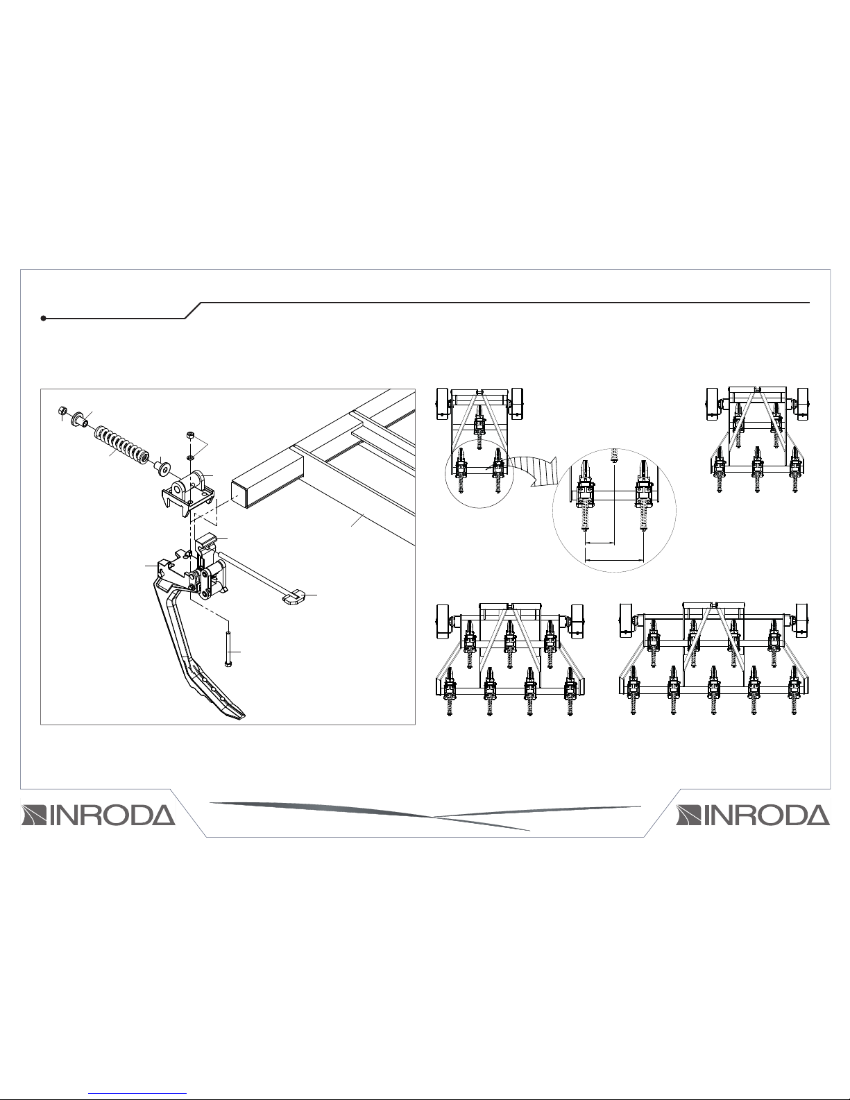
HYDRAULIC SYSTEM ASSEMBLY (11 AND 13 SHANKS)
13
o facilitating the implement transport from the factory to the dealer it leaves
the factory almost assembled to fi nish the assembly procedures you will
need install the shanks. The drawings bellow has been illustrated to show
the right shank position on each models.
Couple in the frame (1) the shank support (2) and the spring support (3)
locking with the bolts (4) washers and nuts (5) install the spring adjustment
rod (6) in the shank auto-return system (7), in the spring support (3) attaching the bushing (8) springs (9) and locking with the nuts (10).
SHANKS ASSEMBLY
10
05
01
09
08
06
04
02
07
03
08
DRAWING 09
Puma 7000 H
Puma 3000 H
Puma 5000 H
Pum 9000 H
DRAWING 10
310
620

14
The drawings bellow has been illustrated the shank right position for each subsoiler model. Pay attention because the shanks are assembly in odd amount
in order to right assemble you need start by the central shank then reaching the ideal spacing for the working and assembly the lateral shanks.
Puma 5000
Puma 9000
Puma 7000
Puma 11000 Puma 13000
375750
750
DRAWING 11

15
PUMA H HITCH PROCEDURE
HITCHING THE SUBSOILER IN THE TRACTOR
To hitching the subsoiler in the tractor couple the implement drawbar (1) on
the tractor drawbar (02), couple the hydraulic hoses from the cylinders in
the quick-coupler.
Before coupling the implement in the tractor, be sure they are ready for this
procedure following the instructions below:
- Remove the drawbar
- When necessary use the tractor extra-weight
- The hitch procedure must be done in plane surface using daylight or good
artifi cial light
- Couple the three point left low arm using the pin (1) on the support “A”
- Couple the three point upper arm on the support “B” and lock with the pin
Then using the tractor height lever hitch the right low arm in the support “C”,
suing the lock as illustrated in drawing 13.
DRAWING 12
DRAWING 13
To coupling the hydraulic system clear the quick-coupler push the
female tip fi rmly into the coupler with another hand install the connector and loosen the quick-coupler. If you have any diffi cult push
the male quick-coupler against a clean and hard surface for relief the
pressure in the tip.
ATTENTION
B
01
A
C
06 - HITCH PROCEDURE
01
02
03

16
D
D
PUMA H ALIGNMENT PROCEDURE
The implement alignment procedure is done following steps below:
Align the upper three point bar in order to the length “D” is same in the both
sides of the tractor using as reference the tractor tyres. The lower tractor
three point arms must be aligned in the same position.
DRAWING 14
PUMA H LEVELING PROCEDURE
DRAWING 15
For leveling the implement follow the instructions below:
Choose a leveled surface, for leveling the implement in the transversal di-
rection (width) use the level from the lower right arm, inspect if the confi gu-
rations is in according to the drawing 15
The leveling longitudinal (length) is done by the three-point upper arm, it
must be done parallel in relation to the terrain.
Manivela de Regulagem
Braço do 3º ponto
Nivelamento longitudinal
(Comprimento)
H
H
Nivelamento Transversal
(Largura)

17
DEPTH ADJUSTMENT FOR SUBSOILER PUMA
07 - ADJUSTMENT AND OPERATIONS
DEPTH ADJUSTMENT FOR SUBSOILER PUMA H
The depth working of subsoiler PUMA H is done by the wheel (1) that keeps
all shanks in same position.
In order to adjusting it loosen the nut (2) move the wheel to the ideal position retighten the nuts.
Adjust the scrapers (3) loosening the nuts (4) moving the scrapers until
the right position, the manufacturer recommends keep the scrapers from 10
com to 20 cm far of the wheel.
The working depth is done by the depth wheel that is controlled by the
hydraulic system (1).
Defi ne the shank depth working raise the wheels until the depth reached
then install the lock device (2) in the hydraulic cylinder rods.
After this adjustment the depth working will be in according to the depth
defi ned because the lock devices not allow that the wheels move for
another position.
DRAWING
16
DRAWING 17
01
02
03
04
01
02
10 a 20 cm

18
PRESSURE ADJUSTMENT IN AUTO-RETURN DEVICE
The subsoiler leaves the factory with the spring adjusted in 30cm (length),
it is indicated for working in normal soil conditions. The increase the spring
pressure adjust is done by the nut “A” to decrease loosen it. The pressure
range is from 27,5cm to 30cm based on the spring length.
ATTENTION
The subsoiler not requires any additional
adjustment in the shanks, if the shank is
working out of the confi gurations, ins-
pect the soil conditions it has been hard
or compressed.
ATTENTION
For the best performance of subsoiler work with less pressure as
possible, but pay attention for de auto-return device not working out
of desired confi gurations.
DRAWING 18 DRAWING 19
30cm
SPACING BETWEEN SHANKS PUMA H
The shank’s spacing must be adjusted when you remove any shank, eg.
the subsoiler used to working with 9 shank right now will working with 7
shanks in according to the soil conditions.
To adjusting the shank’s spacing loosen the nuts (1) and move the shank
(3) to the desired position and retighten the nuts.
DRAWING 20
A
B
01
02

19
COULTER BLADE ADJUSTMENT
REAR ROLLER SUBSOILER PUMA
Conditions as subsoiling depth, amount of straws and moisture requires
adjusts in the height and down-pressure in the coulter blade.
To adjusting the coulter blade’s height (1) loosen the bolts (2) move the
shaft (3) for desired position then retighten the bolts (2).
The coulter blade down-pressure is done by the adjustment of the nuts and
cotter-nuts.
03
01
02
ATTENTION
Pay attention the coulter blade must be aligned with the shanks. All
counter blade should have the same adjustment.
DRAWING
21
The rear roller is proper to maintain the soil in the right position after the
subsoiling procedures, in order to level the terrain allocate the straws and
other debris provide a good conditions for no-till.
The rear roller pressure must be adjusted in according to the soil conditions, and provide a good completion of the job. In order to adjusting the
rear roller down-pressure
user the nuts (1).
To adjusting the right down-
-pressure follow the instructions below:
Adjust the depth working loosen the down-pressure nuts
(1);
Set the subsoiler in work position tighten the nuts until
lock the spring.
Turn twice time each nut to
provide the right pressure for
the springs.
ATTENTION
The device must be adjusted to providing the same down-pressure
in the rear roller, the down-pressure should be adjusted until not to
raise the subsoiler, it will provide a not regular subsoiling procedure.
Do not tighten too the nuts it may result in damages for some parts.
DRAWING 22
01
20
- Before set up the implement adjustment inspect the terrain’s
compaction dimension using proper methods.
- The subsoiler shanks was developed to auto-returning system when touch some debris, in order to unlock the system
just raise the implement after touch the debris.
OPERATIONS
- Retighten the nuts and bolts when you fi nish the fi rst working
day, inspect the pins, cotters pins and others device that may loosen, then inspect every 24 working hours.
- The subsoiling procedure should be done in terrain dry, to remove compaction lays and low areas to improve water drainage.
- The compaction layer is located below the fi rst terrain layer its
from 10 to 15 cm from terrain surface the layer compaction dimension is from 5 cm to 15cm.
- In some terrain conditions the hardest implement adjustment
could be not enough to subsoiling procedure, in these situations
the manufacturer recommends use other implements.
- Pay special attention in the discs gangs retighten daily in the
fi rst working week then repeat this procedure periodically.
- Set a right tractor gear in order it provide extra-power in any
unexpected event.
- The working speed is defi ned in according to the terrain con-
ditions, the manufacturer recommends a working speed from
4,5km/h to 5km/h the high working speed is able to decrease the
implement’s performance.
- Follow the lubrications schedule
- The tractor drawbar usually have a oscillation during the work.

21
TABELA 03
08 - MAINTENANCE
The correct lubrication is very important for providing a high durability and
a good working of the rotating parts of the engine that result in years of
trouble-free from the PUMA.
Before running the subsoiler, lubricate all-grease nipples in accordance
with the schedule on the next pages. Use lubes of high quality recommended by the manufacturer.
Existing lubricante or grease of other brands consult their technical
publication
The Puma subsoiler was developed for a long-term of trouble free in order
to reach this conditions you should realize a right maintenance procedure
as the described below:
- When you store the implement for a long term re-paint, protect the discs
with oil, lubricate all points avoiding the soil touch.
- The discs should be replaced when it decrease the performance, pay
attention in the discs diameter and other damages.
- Inspect all rotating parts replace when it show any worn.
- Re-tighten the bolts daily.
- Inspect daily the shanks tines and replace when it is worn.
- Inspect for leaks in hydraulic system (see more in table 03).
- Use the quick-coupler’s lids to protecting this device.
LUBRICATION
ATTENTION
MANUFACTURER RECOMMENDED GREASE TYPE
PETROBRÁS LUBRAX GMA 2
PETRONAS KP2K
IPIRANGA SUPER GRAXA IPIRANGA
IPIRANGA SUPER GRAXA 2
IPIFLEX 2
CASTROL LM 2
MOBIL MOBILGREASE MP 77
TEXACO MARFAK 2
AGROTEX 2
SHELL GRADUS S1 V150
MOBIL MULTIPURPOSE GREASE H
LITHOLINE MP 2
BARDAHL MAXLUB APG 2 EP
TUTELA KP2K

22
OPERATIONS MAINTENANCE - PROBLEMS DURING THE SUBSOILERS WORKS
The auto-return system not
unlock
The shanks are locked. Lubricate or replace.
The springs are too tighten Adjust the down-pressure as indicated in the label maximum 27.5cm
The frame is cracked
or warped
You working in curves too closed with the subsoiler into
the terrain.
When you maneuvering the implement remove the arms using the tractor remote control.
The auto-return system not unlock Adjust the down-pressure as indicated in the label maximum 27.5cm
Excessive tightening of the Springs Adjust the down-pressure as indicated in the label maximum 27.5cm
The springs are too tighten Low quality bolt Replace for spare parts the manufacturer recommends steel bolts 8.8
Subsoiler enter into the soil.
Implement working position is out of horizontal position Set the implement in horizontal position using the drawbar.
The shanks tines are worn Inverse the shank or replace it.
The adjustment bolt is short Turn the two bolts in counterclockwise direction until reach the right position. Do
the same confi guration in booth bolts.
The auto-returning system
unlock unexpected way.
The terrain there are many debris eg. stones stumps
roots.
Decrease the working speed or avoiding this areas.
Soil too compacted Replace the shanks tine from the 3” to 2”.
The tractor has high-power for this implement or high
speed.
Use the power and speed s recommended by the manufacturer.
Springs down pressure are not enough. Adjust the down-pressure as indicated in the label maximum 27.5cm.
The shanks devices are worn. Replace the worn parts.
PROBLEM POSSIBLE CAUSE SOLUTION
TABLE 04

23
OPERATIONS MAINTENANCE - PROBLEMS WITH HYDRÁULICS SYSTEM
Hydraulic cylinder leaks
Dirty oil High working pressure Replace oil and fi lters Adjust the pressure using a manometer,
the manufacturer recommends
Damaged seal rings Shank damaged. 180kg/cm2. Replace the seal rings. Replace the shanks
Reparos danifi cados. Substituir os reparos.
Haste danifi cada.* Substituir a haste.
Leaks in the hoses
with the connector
SAE JIC 37.
The conical device damaged. Cut of the hoses and install again.
Tighten not enough. Re-tighten carefully.
The implement is not moving or
moving too slow
Problem in tractor hydraulic system. Inspect and use a right tractor.
The oil level is low. Fill the oil.
Hoses reversed. Inspect the system and install the hoses in right position.
The hydraulic cylinder is damaged. Replace the hydraulic cylinder.
The hydraulic command pressure not enough Replace oil and fi lters Adjust the pressure using a manometer, the manufacturer
recommends 180kg/cm2.
The connectors pressure is not the same. Adjust and replace when necessary.
Hydraulic hoses clogged or damaged. Inspect and replace when necessary.
The equipment is moving
without use the hydraulic
controls
Seals rings are damaged. Replace the seal rings.
Hydraulic cylinder seal rings damaged. Inspect the hydraulic cylinder and replace seal device.
The nuts are loosen Tighten the hydraulic cylinder bolts carefully.
There is not enough seal tape. Use enough seal tape.
The quick-coupler not
connect.
The quick-coupler has different models. Use the same kind of quick-coupler.
Leaks in the hoses or
connector.
Not enough seal tape. Use enough seal tape.
The connector is not tighteen. Re-tighten carefully.
PROBLEM POSSIBLE CAUSE SOLUTION
TABLE 05
24
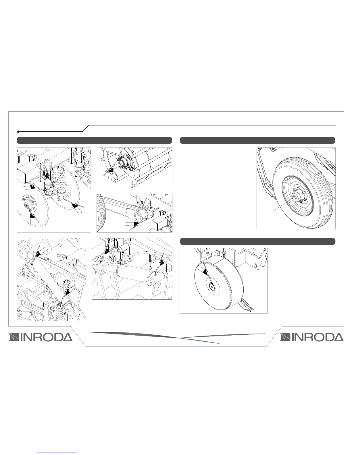
LUBRICATION POINTS
LUBRICATE EVERY 60 WORKING HOURSLUBRICATE EVERY 10 WORKING HOURS
Lubricate periodically the wheel
housing of you subsoiler PUMA,
the manufacturer recommends lubricate every 60 working hours and
when you fi nish the season, follow
the instructions below:
Remove the dust cap (1) from the
wheel housing, Clear the worn grease Inspect the bearing, adjust the
loosen when necessary.
Insert the new grease on the dust
cap and wheel housing.
Reinstall the dust cap (1) in the
wheel as illustrated on the drawing
24.
DRAWING
23
DRAWING 24
01
LUBRICATE EVERY 100 WORKING HOURS
DRAWING 25

25
TYRES INFLATION
Properly infl ating of grader tyres to improve the life and performance of the
tyres and implement, avoiding premature wear the manufacturer recom-
mends that right infl ation rate is 60lb/pol for tyres model 7-50/x 16.
HIGHT
PRESSURE
LOW PRESSURE RECOMMENDED
PRESSURE
DRAWING 26
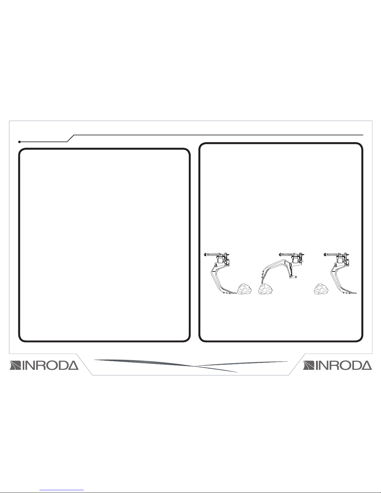
SUBSOILER TRANSPORT
To transport the subsoiler follow the instructions bellow:
Remove the springs rod (1) that lock the oscillation bar, including nuts,
bushing and springs.
Then move the rear roller (02) in the raise position in order to it be positioned over the implement, keeping the spring rod free as illustrated in the
view “A”.
01
DRAWING 27
DETALHE “A”
01
02

26
The drawing shown in this manual and catalogue parts are merely
illustrative
ATTENTION
If you have any doubt Do not use this implement contact the Inroda Techinical support
Assistência@inroda.com.br
09 - CLEAN PRODUCERE
- Inspect all rotation parts, when they are loosen adjust and replace parts
damaged or worn it will keep the hoist able to working in the next season.
Use only INRODA spare parts.
-Before storing the hoist clear it using neutral detergent, check the paint
when it is damaged repaint then use paint protector oil.
-Lubricate all parts
- Store the hoist in dry place, correctly positioned, avoiding that the imple-
ment touch directly the fl oor.
10 - SPARE PARTS
Use only Genuine Inroda Parts to yield the best results from your work
without compromising your Equipment.
11 - IDENTIFICATION
When consulting the parts catalog or soliciting INRODA technical
assistance, always indicate the serial number (1), model (2), and the date
of manufacture (3), that can be found on the equipment identifi cation tag
(Drawing 28).
1
2 3
DRAWING 28

Fill out the data below to always have a record of the correct information about your equipment.
Owner:___________________________________________________________________________________________________________________
Retailer:__________________________________________________________________________________________________________________
Farm:___________________________________________________________________________________________________________________
City:__________________________________________________________________________ State:_____________________________________
Warrenty Number:________________________________________________________________________________________________________
Model:___________________________________________________________________________________________________________________
Serial Number:____________________________________________________________________________________________________________
Date purchased:_______/ _______/ ________ Receipt Number:____________________________________________________________________
________________________________________________________________________________________________________________________
________________________________________________________________________________________________________________________

Notes:

Prepared by: João Paulo
Ilustrations: Hermida
Diagram: Wellington Caio
Code: 210259
Rua Piauí, 810 - Cx. Postal 293 CEP 18700-030 - Avaré - SP - Brasil
Website: http://www.inroda.com.br - E-mail: inroda@inroda.com.br
Phone (14) 3711-3000 - Fax (14) 3711-3002
 Loading...