

IPS 247BT
INSTRUCTION MANUAL
Car Stereo CD/CDR/CDRW/MP3/WMA Player
with PLL MW/FM Stereo Radio
Radio Data System with PTY
USB / MMC / SD Card Input
Bluetooth Function in Mobile Phone
and Detachable Front Panel System
DISP
BD/PAU
MD/MU
1 TOP
SCAN
IPS 247BT CD/MP3/WMA PLAYER 4x60WATTS
2
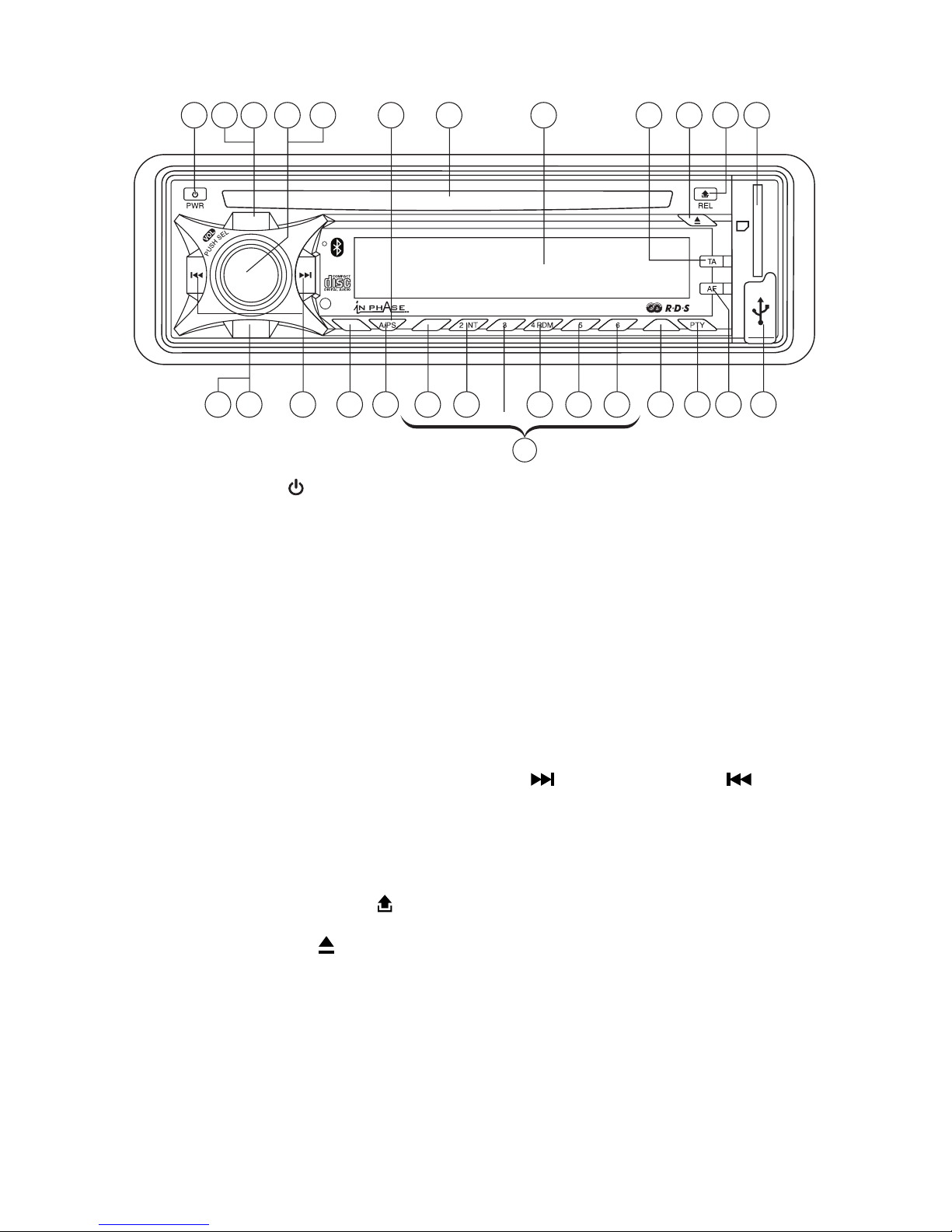
LOCATION OF PARTS AND CONTROLS
1. POWER ON/OFF ( )
2. FUNCTION SELECT BUTTON: BASS/TREBLE/BALANCE/FADER/TA SEEK/MASK
DPI/RETUNE/AUDIO DSP/LOUDNESS/ESP/CD MULTI/SCROLL/BEEP/STEREO/
LOCAL/PAIRING
3. VOL UP/VOL DOWN FOR BASS/TREBLE/BALANCE/FADER/TA SEEK/MASK DPI/
RETUNE/AUDIO DSP/LOUDNESS/ESP/CD MULTI/SCROLL/BEEP/STEREO/LOCAL/
PAIRING
4. PRESET STATIONS (1,2,3,4,5,6)
5. ‘AF’ function (ALTERNATIVE FREQUENCIES)
6. ‘TA’ function (TRAFFIC ANNOUNCEMENT)
7. ‘PTY’ function (PROGRAM TYPE)
8. DISPLAY BUTTON (DISP)
9. MODE BUTTON (MD)
10. BAND BUTTON (BD)
11. AUTOMATIC OR MANUAL TUNING (FREQ UP OR FREQ DOWN /
CD TRACK/SEARCH BUTTON
12. AUTO SEEK SEARCH TUNING (A/PS)
13. ‘SCAN’ AUTOMATIC TUNING CONTROL (SCAN)
14. MUTE BUTTON (MU)
15. LCD DISPLAY
16. PANEL RELEASE BUTTON ( )
17. CD SLOT
18. CD EJECT BUTTON ( )
19. TOP BUTTON
20. PAUSE BUTTON
21. INTRO BUTTON (Preview all Tracks)
22. REPEAT BUTTON
23. RANDOM BUTTON
24, 25. + 10 TRACK SEARCH UP/DOWN
26. USB PORT
27. MULTI-MEDIA CARD (MMC) / SD CARD SLOT
DISP
BD/PAU
MD/MU
1 TOP
SCAN
IPS 247BT CD/MP3/WMA PLAYER 4x60WATTS
1517223141 9 2 18 27166
211912131020 11 23 24 25 8 7 265
4
(1-6)
DISP
BD/PAU
MD/MU
1 TOP
SCAN
IPS 247BT CD/MP3/WMA PLAYER 4x60WATTS

3
B
A
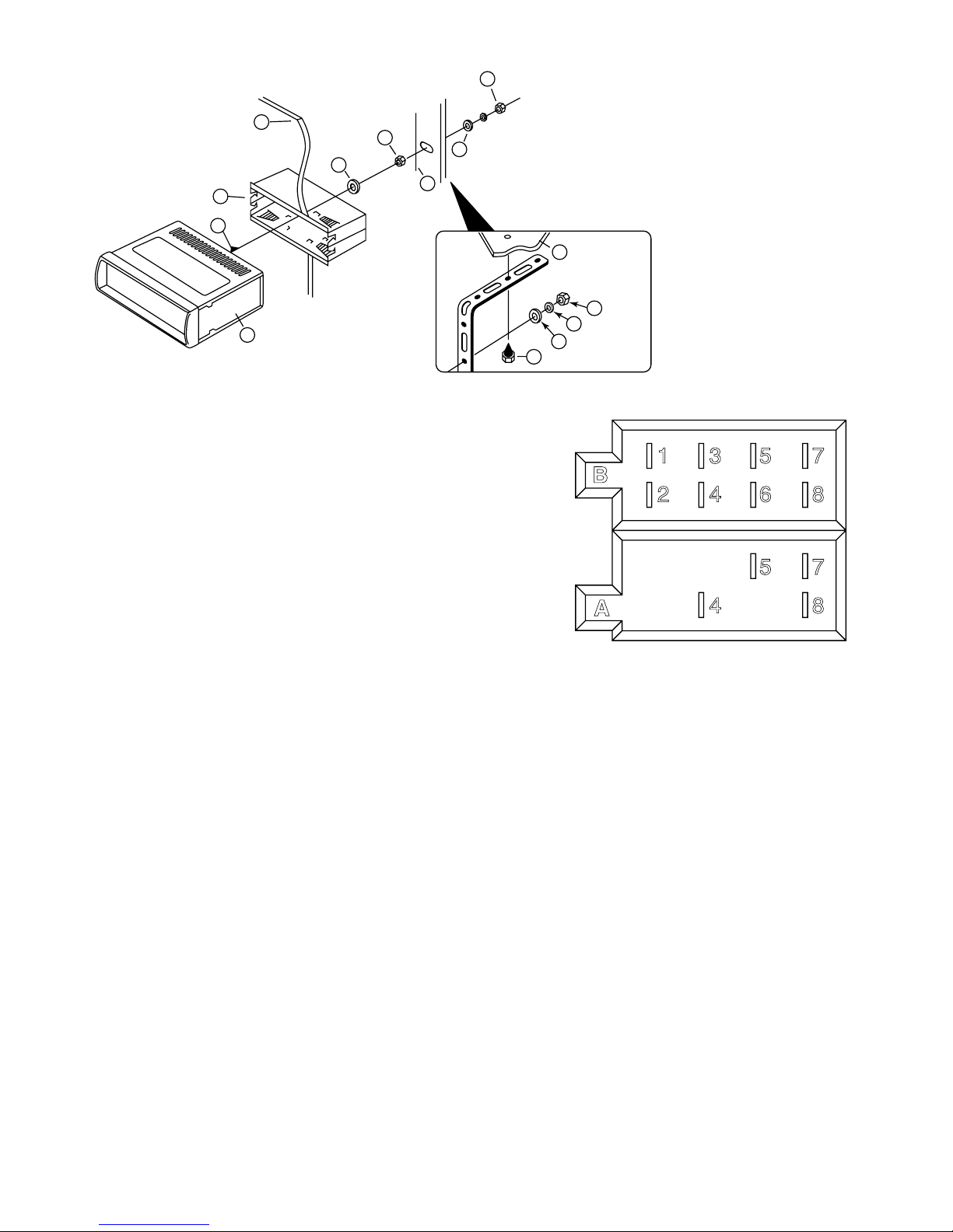
INSTALLATION
PRECAUTIONS
• Choose the mounting location carefully so that the unit will not interfere with the normal
driving functions of the driver.
• Avoid installing the unit where it would be subject to high temperatures, such as from direct
sunlight or hot air from the heater, or where it would be subject to dust, dirt or excessive
vibration.
• Use only the supplied mounting hardware for a safe and secure installation.
• Be sure to remove the front panel before installing the unit.
Mounting angle adjustment
Adjust the mounting angle to less than 20°.
MOUNTING EXAMPLE
Installation in the dashboard
Note: Keep the release key in a safe place as you may need it in the future, to remove the
unit from the car.
Detaching and attaching the front panel
The front panel of this unit can be detached in order to prevent the unit from being stolen.
DETACHING THE FRONT PANEL
Before detaching the front panel, first be sure to press the PWR
off first. Press the button to release front panel.
Pull out the panel towards you in order to detach completely the
panel from the main unit.
Refer to instruction.
ATTACHING THE FRONT PANEL
Make sure the front panel is in the right way up when attaching it to the unit as it cannot be
attached upside down. Bring side B of panel to side A of main unit.
Insert the panel in and push until it clicks.
Panel is attached.
Notes:
• Do not press the front panel hard against the unit when attaching it. It can be easily attached
by pressing it lightly against the unit.
• When you carry the front panel with you, put it in the supplied front panel case.
• Do not press hard or give excessive pressure to the display window of the front panel when
attaching it to the unit.
2
182mm
53mm
3
4
TAP
1
2
1
3
Bend these
claws, if necessary
Release screw and
bracket
B
A
Front Panel
Rear of the
front panel
Main unit
4
10
7
1
2
3
4
4
4
5
5
6
6
8
9
TO SUPPORT THE UNIT
ISO CONNECTOR
RCA Jack Line Out
White (left) Red (right)
RCA Jack Line In
White (left) Red (right)
CONNECTOR A
4. MEMORY +12V
5. AUTO ANTENNA OUTPUT
7. +12V (TO IGNITION KEY)
8. GROUND
Note: (connector A no. 7) must be connected by car ignition key in order to avoid that car battery getting drained when the car will be not used for long period.
CONNECTOR B
1. REAR RIGHT SPEAKER (+)
2. REAR RIGHT SPEAKER (-)
3. FRONT RIGHT SPEAKER (+)
4. FRONT RIGHT SPEAKER (-)
5. FRONT LEFT SPEAKER (+)
6. FRONT LEFT SPEAKER (-)
7. REAR LEFT SPEAKER (+)
8. REAR LEFT SPEAKER (-)
Maintenance
FUSE REPLACEMENT
If the fuse blows, check the power connection and replace the fuse. If the fuse blows again
after the replacement, there may be an internal malfunction. In this case, consult your nearest
repair center.
Warning
Use the specified amperage fuse for each lead. Use of a higher amperage fuse may cause
serious damage.
1. UNIT
2. RELEASE CASE
3. DASH BOARD
4. HEX NUT
5. LOCK WASHER
6. PLAIN WASHER
7. CAR BODY
8. REAR SUPPORT STRAP
9. TAPPING SCREW
10. M5 X 15 HEX BOLT
Dashboard
B
1 3 5 7
2 4 6 8
5 7
4 8
A

5
TA SEEK
SEL
2 sec.
TA SEEK / TA ALARM
TA SEEK
SEL
MASK DPI
SEL
2 sec.
MASK DPI / MASK ALL
TA SEEK
SEL
RETUNE
SEL
MASK DPI
SEL
TA SEEK
SEL
2 sec.
SEL
DSP ONMASK DPI
SEL
RETUNE
SEL
2 sec.
RETUNE L / RETUNE S
POP --- ROCK --- CLASSIC --- FLAT --- DSP OFF
VOL
VOL
VOL
VOL
TA SEEK
SEL
2 sec.
TA SEEK / TA ALARM
TA SEEK
SEL
MASK DPI
SEL
2 sec.
MASK DPI / MASK ALL
VOL
VOL
TA SEEK
SEL
2 sec.
TA SEEK / TA ALARM
TA SEEK
SEL
MASK DPI
SEL
2 sec.
MASK DPI / MASK ALL
TA SEEK
SEL
RETUNE
SEL
MASK DPI
SEL
2 sec.
RETUNE L / RETUNE S
VOL
VOL
VOL
1 3
2
4
2
5
2
6
2 2
1. POWER ON/OFF (PWR)
By pressing this key, the unit is turned on or off.
This unit is turned on by pressing any key.
2,3.
FUNCTION SELECT BUTTON: BASS/TREBLE/BALANCE/FADER / TA SEEK/MASK DPI/RETUNE/
AUDIO DSP/LOUDNESS/ESP/CD MULTI/BEEP/STEREO/LOCAL/PAIRING
Turning the VOL knob Right or Left (3), you can adjust VOL/BASS/TREB/BAL/FAD. To select other
functions, press the VOL knob shortly until the desired functions is shown on the display. Figure 1
shows how control functions are selected using the SEL button.
Fig. 1 Selection of sound control functions
1. VOL 2. SEL 3. BAS 4. TRE 5. BAL 6. FAD
Turning the VOL knob Right or Left. Increase or decrease the volume by turning
VOLVOL
or
VOLVOL
. These
buttons can be used to adjust the BASS, TREBLE, BALANCE and FADER.
TA SEEK/TA ALARM (2)
When press the SEL button for more than 2 seconds, it is activated as selecting mode of these func-
tion.
TA SEEK Mode or TA ALARM mode is selected by
VOLVOL
or
VOLVOL
.
- TA SEEK mode:
When newly turned station does not receive TP information for 5 sec., the radio retunes to next station
which has not the same station (PI) as the last station, but has the TP information.
In TA seek mode, the current station can be changed to the completely different station because the
unit searches TP station when the field strength of the current station is very weak, or the current
station has no TP signal.
- TA ALARM mode:
Any automatic retune mode is not activated, just can hear Beep sound.
MASK DPI (2)
When press the SEL button for more than 2 seconds, it is activated as selecting mode of these function.
MASK DPI: masked only the AF which has different PI.
MASK ALL: masked the AF which has different PI and NO RDS signal with field strength.
RETUNE L / S CONTROLS (2)
When press the SEL button for more than 2 seconds, it is activated as selecting Retune mode.
RETUNE L: Select 90 seconds as the initial time of automatic TA search.
RETUNE S: Select 30 seconds as initial time.
AUDIO DSP CONTROLS (2)
When press the SEL button for more than 2 seconds, it is activated as selecting mode of these function.
LOUDNESS CONTROLS (2)
When press the SEL button for more than 2 seconds, it is activated as selecting mode of these function.
TA SEEK
SEL
2 sec.
TA SEEK / TA ALARM
VOL

6
TA SEEK
SEL
2 sec.
SEL
SEL
MASK DPI
SEL
ESP
ESP 10 / ESP 40
TA SEEK
SEL
2 sec.
TA SEEK / TA ALARM
TA SEEK
SEL
MASK DPI
SEL
2 sec.
MASK DPI / MASK ALL
TA SEEK
SEL
RETUNE
SEL
RETUNE DSP
SEL
MASK DPI
SEL
TA SEEK
SEL
2 sec.
SEL
SEL
MASK DPI
SEL
RETUNE DSP
SEL
TA SEEK
SEL
2 sec.
SEL
DSP ONMASK DPI
SEL
RETUNE
SEL
2 sec.
RETUNE L / RETUNE S
POP --- ROCK --- CLASSIC --- FLAT --- DSP OFF
LOUD
LOUD ON/OFF
TA SEEK
SEL
2 sec.
SEL
LOUD
SEL
MASK DPI
SEL
SEL
RETUNE DSP
SEL
ESP
SEL
SEL
MULTI
SEL SEL
TA SEEK
SEL
2 sec.
SEL
LOUD
SEL
MASK DPI
SEL
SEL
RETUNE DSP
SEL
ESP
SEL
MULT
STEREO/MONO
STEREO
SEL
BEEP
VOL
BEEP ON/OFF
SEL SEL
BEEP
VOL
SCROLL
SCROLL
TA SEEK
SEL
2 sec.
SEL
LOUD
SEL
MASK DPI
SEL
SEL
RETUNE DSP
SEL
ESP
MULT ON/OFF
SEL
MULT
VOL
VOL
VOL
VOL
VOL
VOL
VOL
SEL
SCROLL SCROLL 1/2
VOL
TA SEEK
SEL
2 sec.
SEL
LOUD
SEL
MASK DPI
SEL
SEL
RETUNE DSP
SEL
ESP
SEL
MULT
TA SEEK
SEL
2 sec.
SEL
SEL
MASK DPI
SEL
ESP
ESP 10 / ESP 40
TA SEEK
SEL
2 sec.
TA SEEK / TA ALARM
TA SEEK
SEL
MASK DPI
SEL
2 sec.
MASK DPI / MASK ALL
TA SEEK
SEL
RETUNE
SEL
RETUNE DSP
SEL
MASK DPI
SEL
TA SEEK
SEL
2 sec.
SEL
SEL
MASK DPI
SEL
RETUNE DSP
SEL
TA SEEK
SEL
2 sec.
SEL
DSP ONMASK DPI
SEL
RETUNE
SEL
2 sec.
RETUNE L / RETUNE S
POP --- ROCK --- CLASSIC --- FLAT --- DSP OFF
LOUD
LOUD ON/OFF
SEL
TA SEEK
SEL
2 sec.
SEL
LOUD
SEL
MASK DPI
SEL
SEL
RETUNE DSP
SEL
ESP
MULT ON/OFF
SEL
MULT
VOL
VOL
VOL
VOL
VOL
VOL
VOL
TA SEEK
SEL
2 sec.
SEL
SEL
MASK DPI
SEL
ESP
ESP 10 / ESP 40
TA SEEK
SEL
2 sec.
TA SEEK / TA ALARM
TA SEEK
SEL
MASK DPI
SEL
2 sec.
MASK DPI / MASK ALL
TA SEEK
SEL
RETUNE
SEL
RETUNE DSP
SEL
MASK DPI
SEL
TA SEEK
SEL
2 sec.
SEL
SEL
MASK DPI
SEL
RETUNE DSP
SEL
TA SEEK
SEL
2 sec.
SEL
DSP ONMASK DPI
SEL
RETUNE
SEL
2 sec.
RETUNE L / RETUNE S
POP --- ROCK --- CLASSIC --- FLAT --- DSP OFF
LOUD
LOUD ON/OFF
SEL
VOL
VOL
VOL
VOL
VOL
VOL
LOUD ON/OFF mode is selected by
VOLVOL
or
VOLVOL
. The bass and treble response will be boosted.
ESP MODE (2)
When press the SEL button for more than 2 seconds, it is activated as 12 sec. or 45 sec. of ESP mode
can be selected.
Note: 10 sec./40 sec. for CD, 120 sec. for MP3 automatically works.
MULTI CD SECTION MODE (2)
When press the SEL button for more than 2 seconds, it is activated as selecting mode of these function.
CD MULTI ON/OFF mode is selected by
VOLVOL
or
VOLVOL
. CD MULTI ON: Read multi section CD.
CD MULTI OFF: Read first section only.
SCROLL MODE
When press the SEL button for more than 2 seconds, it is activated as selecting mode of these function.
SCROLL 1: Unit displays song details but no text scrolling.
SCROLL 2: Unit displays song details and scrolls the text information to the left.
BEEP MODE (2)
When press the SEL button for more than 2 seconds, it is activated as selecting mode of these function.
BEEP ON: BEEP sound can be heard from speaker when the buttons are pressed.
STEREO/MONO (2)
When press the SEL button for more than 2 seconds, it is activated as selecting mode of these function.
When FM stations are weak and are disturbed, listening can be improved by selecting MONO.
LOCAL/DX (2)
When press the SEL button for more than 2 seconds, it is activated as selecting mode of these function.
“Local” position in areas with strong signals to let radio stop at only strong stations during manual
tuning (LOC appears). Select Distant position in areas with weak signals to listen to all stations.
TA SEEK
SEL
2 sec.
SEL
SEL
MASK DPI
SEL
TA SEEK
SEL
2 sec.
TA SEEK / TA ALARM
TA SEEK
SEL
MASK DPI
SEL
2 sec.
MASK DPI / MASK ALL
TA SEEK
SEL
RETUNE
SEL
RETUNE DSP
SEL
MASK DPI
SEL
TA SEEK
SEL
2 sec.
SEL
DSP ONMASK DPI
SEL
RETUNE
SEL
2 sec.
RETUNE L / RETUNE S
POP --- ROCK --- CLASSIC --- FLAT --- DSP OFF
LOUD ON/OFF
VOL
VOL
VOL
VOL
VOL
TA SEEK
SEL
2 sec.
SEL
SEL
MASK DPI
SEL
ESP
ESP 10 / ESP 40
TA SEEK
SEL
2 sec.
TA SEEK / TA ALARM
TA SEEK
SEL
MASK DPI
SEL
2 sec.
MASK DPI / MASK ALL
TA SEEK
SEL
RETUNE
SEL
RETUNE DSP
SEL
MASK DPI
SEL
TA SEEK
SEL
2 sec.
SEL
SEL
MASK DPI
SEL
RETUNE DSP
SEL
TA SEEK
SEL
2 sec.
SEL
DSP ONMASK DPI
SEL
RETUNE
SEL
2 sec.
RETUNE L / RETUNE S
POP --- ROCK --- CLASSIC --- FLAT --- DSP OFF
LOUD
LOUD ON/OFF
TA SEEK
SEL
2 sec.
SEL
LOUD
SEL
MASK DPI
SEL
SEL
RETUNE DSP
SEL
ESP
SEL
SEL
MULTI
BEEP ON/OFF
SEL SEL
BEEP
VOL
SCROLL
TA SEEK
SEL
2 sec.
SEL
LOUD
SEL
MASK DPI
SEL
SEL
RETUNE DSP
SEL
ESP
MULT ON/OFF
SEL
MULT
VOL
VOL
VOL
VOL
VOL
VOL
VOL
SEL
SCROLL SCROLL 1/2
VOL
TA SEEK
SEL
2 sec.
SEL
LOUD
SEL
MASK DPI
SEL
SEL
RETUNE DSP
SEL
ESP
SEL
MULT
TA SEEK
SEL
2 sec.
SEL
SEL
MASK DPI
SEL
ESP
ESP 10 / ESP 40
TA SEEK
SEL
2 sec.
TA SEEK / TA ALARM
TA SEEK
SEL
MASK DPI
SEL
2 sec.
MASK DPI / MASK ALL
TA SEEK
SEL
RETUNE
SEL
RETUNE DSP
SEL
MASK DPI
SEL
TA SEEK
SEL
2 sec.
SEL
SEL
MASK DPI
SEL
RETUNE DSP
SEL
TA SEEK
SEL
2 sec.
SEL
DSP ONMASK DPI
SEL
RETUNE
SEL
2 sec.
RETUNE L / RETUNE S
POP --- ROCK --- CLASSIC --- FLAT --- DSP OFF
LOUD
LOUD ON/OFF
TA SEEK
SEL
2 sec.
SEL
LOUD
SEL
MASK DPI
SEL
SEL
RETUNE DSP
SEL
ESP
SEL
SEL
MULTI
SEL SEL
TA SEEK
SEL
2 sec.
SEL
LOUD
SEL
MASK DPI
SEL
SEL
RETUNE DSP
SEL
ESP
SEL
MULT
SEL
TA SEEK
SEL
2 sec.
SEL
LOUD
SEL
MASK DPI
SEL
SEL SEL
RETUNE DSP
SEL
ESP
MULT
LOCAL/DX
LOCAL
SEL
STEREO
SEL
BEEP
VOL
STEREO/MONO
STEREO
SEL
BEEP
VOL
BEEP ON/OFF
SEL SEL
BEEP
VOL
SCROLL
SCROLL
SEL
SCROLL
TA SEEK
SEL
2 sec.
SEL
LOUD
SEL
MASK DPI
SEL
SEL
RETUNE DSP
SEL
ESP
MULT ON/OFF
SEL
MULT
VOL
VOL
VOL
VOL
VOL
VOL
VOL
SEL
SCROLL SCROLL 1/2
VOL
TA SEEK
SEL
2 sec.
SEL
LOUD
SEL
MASK DPI
SEL
SEL
RETUNE DSP
SEL
ESP
SEL
MULT

7
TA SEEK
SEL
2 sec.
SEL
SEL
MASK DPI
SEL
ESP
ESP 10 / ESP 40
TA SEEK
SEL
2 sec.
TA SEEK / TA ALARM
TA SEEK
SEL
MASK DPI
SEL
2 sec.
MASK DPI / MASK ALL
TA SEEK
SEL
RETUNE
SEL
RETUNE DSP
SEL
MASK DPI
SEL
TA SEEK
SEL
2 sec.
SEL
SEL
MASK DPI
SEL
RETUNE DSP
SEL
TA SEEK
SEL
2 sec.
SEL
DSP ONMASK DPI
SEL
RETUNE
SEL
2 sec.
RETUNE L / RETUNE S
POP --- ROCK --- CLASSIC --- FLAT --- DSP OFF
LOUD
LOUD ON/OFF
TA SEEK
SEL
2 sec.
SEL
LOUD
SEL
MASK DPI
SEL
SEL
RETUNE DSP
SEL
ESP
SEL
SEL
MULTI
SEL SEL
TA SEEK
SEL
2 sec.
SEL
LOUD
SEL
MASK DPI
SEL
SEL
RETUNE DSP
SEL
ESP
SEL
MULT
SEL
TA SEEK
SEL
2 sec.
SEL
LOUD
SEL
MASK DPI
SEL
SEL SEL
RETUNE DSP
SEL
ESP
MULT
LOCAL/DX
LOCAL
SEL
STEREO
SEL
BEEP
VOL
STEREO/MONO
STEREO
SEL
BEEP
VOL
BEEP ON/OFF
SEL SEL
BEEP
VOL
SCROLL
SCROLL
SEL
SCROLL
SEL
TA SEEK
SEL
2 sec.
SEL
LOUD
SEL
MASK DPI
SEL
SEL SEL
RETUNE DSP
SEL
ESP
MULT
LOCAL
SEL
PAIRING
SEL SEL
STEREO
SEL
BEEP
SEL
SCROLL
TA SEEK
SEL
2 sec.
SEL
LOUD
SEL
MASK DPI
SEL
SEL
RETUNE DSP
SEL
ESP
MULT ON/OFF
SEL
MULT
VOL
VOL
VOL
VOL
VOL
VOL
VOL
SEL
SCROLL SCROLL 1/2
VOL
TA SEEK
SEL
2 sec.
SEL
LOUD
SEL
MASK DPI
SEL
SEL
RETUNE DSP
SEL
ESP
SEL
MULT
PAIRING MODE (2)
When press the SEL button for more than 2 seconds, it is activated as selecting mode of these func-
tion. (Please refer to HOW TO PERFORM PAIRING on page 10)
4. PRESET STATIONS (1,2,3,4,5,6)
(A) RADIO MODE:
When pressed momentarily, these keys select a preset station directly. When pressed longer than 1
sec., current station is stored in preset memory bank. When PTY mode is selected, the PTY switch
is shared as follows:
PTY music group ---- PTY speech group ---- OFF
MUSIC SPEECH
1. POP M, ROCK M 1. NEWS, AFFAIRS, INFO
2. EASY M, LIGHT M 2. SPORT, EDUCATE, DRAMA
3. CLASSICS, OTHER M 3. CULTURE, SCIENCE, VARIED
4. JAZZ, COUNTRY 4. WEATHER, FINANCE, CHILDREN
5. NATION M, OLDIES 5. SOCIAL, RELIGION, PHONE IN
6. FOLK M 6. TRAVEL, LEISURE, DOCUMENT
(B) CD/MP3/WMA PLAYER MODE:
1. PAUSE 2. INT 3. RPT 4. RDM
USING THE RDS FUNCTION
What is RDS?
The RDS (Radio Data System) is a digital information system developed by the EBU (European Broadcast Union). Piggy-backed on normal FM broadcasts, RDS offers a variety of information services and
automatic retuning functions for RDS-compatible car stereos.
In 1988, RDS became available in the United Kingdom, France, West Germany, Ireland and Sweden.
Test transmissions are being conducted in many other European countries. It is expected that RDS will
be available in most western European countries in the near future.
5. ‘AF/REG’ function (ALTERNATIVE FREQUENCIES)
When pressed momentarily, AF/REG switching mode is selected.
When AF/REG switching mode is selected, the radio checks the signal strength of the AF all the time.
When pressed long, it is activated as regional mode ON/OFF.
– Regional mode ON:
AF switching or PI SEEK is implemented to the station which have all PI codes same as current
station. REG segment is turned on in LCD display.
– Regional mode OFF
The regional code in the format of PI code is ignored when AF switching or PI SEEK is implemented.
6. ‘TA’ function (TRAFFIC ANNOUNCEMENT)
When pressed momentarily, it is activated as TA mode on or off
When TA mode is on and traffic announcement is transmitted
– When the unit is CD/MP3 mode, it will switch to radio mode temporarily.
– If the volume level was under the threshold point, it will be raised to the threshold point.
– When TP station is received, TP segment is turned on in LCD display.
7. ‘PTY’ function (PROGRAM TYPE)
PTY MUSIC ---- PTY SPEECH ---- PTY OFF
While selecting PTY type, its selection is implemented by preset buttons as described in preset key.
When PTY is selected, the radio starts to search corresponding PTY information, and stops if the
corresponding PTY information is detected.
8. DISPLAY (DISP)
When this key is pressed, it is operated as the conversion of each display mode as follow.
1) In case of receiving RDS station.
RADIO MODE
PS ---- CT ---- FREQ ---- PTY

8
CD/MP3/WMA PLAYER MODE
CDP ---- CT ---- PS ---- FREQ ---- PTY
2) In case of receiving NON RDS station
RADIO MODE
FREQ ---- CLOCK ----NO PTY
CD/MP3/WMA PLAYER MODE
CDP ---- FREQ ---- CLOCK ---- NO PTY
Each display time is several seconds, and come back to 1’st position after several seconds.
Notes: • CT = clock time • FREQ = frequency • CDP = CD Player
9. MODE BUTTON (MD)
By pressing this key, user can select. AUX/TUNER/CD-MP3/USB or MMC/SD mode.
10. BAND BUTTON (BD)
Each band is toggled cyclically by pressing this key FM1---FM2---FM3--MW1--MW2.
11. AUTOMATIC OR MANUAL TUNING (FREQ UP OR FREQ DOWN )
(A) RADIO MODE
When pressed momentarily, these keys are operated as MANUAL tuning mode.
When pressed longer than 1 sec., they are operated as SEEK tuning mode.
(B) CD/MP3 PLAYER MODE
When pressed momentarily, they are operated as TRACK UP or TRACK DOWN mode.
When pressed longer than 1 sec., they are operated as CUE or REVIEW mode.
12. AUTO SEEK SEARCH TUNING (A/PS)
By pressing shortly, the radio searches for each preset station.
When field strength level is bigger than the threshold level of stop level, the radio is holding at that
preset number for 5 sec. with releasing mute, and then searches again.
By pressing longer than 1 sec, and then 6 strongest stations are preset to the corresponding preset
number. When AS operation is finished, the radio executes the preset scan.
13. ‘SCAN’ AUTOMATIC TUNING CONTROL (SCAN)
This key is operated as RADIO SCAN. The operation is similar as normal search but different thing
is holding 5 seconds on every station detected in RADIO SCAN mode.
14. MUTE BUTTON (MU)
Press and hold this button to mute the sound at once. Press again to return to previous volume level.
15. LCD DISPLAY
The Liquid Crystal Display will display the current state of the unit.
16. PANEL RELEASE BUTTON ( )
Press this button and the right-hand part of the panel will be released.
CD/MP3/WMA CONTROL LOCATION OF PARTS
17. CD SLOT
Carefully insert the CD into the disc slot with the label side uppermost. The CD starts automatically
play.
18. CD EJECT BUTTON
Press the EJECT button to remove the CD.
19. TOP BUTTON
Press to play first song of disc.
20. PAUSE BUTTON
During “PLAY”, press (20) button to “PAUSE”. Press it again to resume play.

9
TRACK/SEARCH BUTTON (11)
FORWARD AND REVERSE TRACK SEARCH (or changing songs)
Press the SKIP button ( or ) during play to go to the desired track(song).
....REVERSE ....FORWARD
Press and hold the SKIP button ( or ) during play to scan the disc at high speed. When the desired
music section of the disc is found, release the button. Normal play will resume.
21. INTRO BUTTON (Preview all Tracks)
When this button is pressed, “INT ON” indication is displayed and the first several seconds of each
track of the disc is played. Press again to stop intro and listen to track.
22. REPEAT BUTTON
When this button is pressed, “RPT ON” indication is displayed and play of the selected track will be
continually repeated until the Track repeat mode is cancelled by pressing ‘RPT’ button again.
23. RANDOM BUTTON
When this button is pressed, “RDM ON” indication is displayed and each track of the disc is played in
random instead of normal progression. To cancel RANDOM mode, press ‘RDM’ button (24) again.
24, 25. 10 TRACK UP/DOWN SELECT: (In case of MP3 files)
M5: 10 Track down / M6: 10 Track up
HOW TO SELECT MP3/WMA FILES
1. Searching Track:
• Press and hold “A/PS”, then search track is activated.
• Press “SEL” button, then the first digit will flash.
• Rotary “VOL knob to right or left”, select first digit desired.
• Press “SEL” button, then the first digit is fixed and second digit will flash.
• Rotary “VOL knob to right or left”, select 2’nd 3’rd respectively.
• Then automatically the song selected will start.
2. Searching Character:
• Press and hold “A/PS”. Press “A/PS” again, then character search mode is activated.
• Press “SEL” button, then “A” character is displayed.
• Rotary “VOL knob to right or left”, you can select the desired letter.
• Press “SEL” button longer than 2 sec.
• The song with the same character you selected is displayed.
• Rotary “VOL knob to right or left”, you can select the desired song.
• Press “SEL” button, then the song selected will start.
3. Searching File Name:
• Press and hold “A/PS”. Press “A/PS” again, then directory search is activated.
• Press “SEL” button, then the first directory is displayed.
• Rotary “VOL knob to right or left”, you can select the desired directory.
• Press “SEL” button again, then the directory is fixed and the first file name is displayed.
• Rotary “VOL knob to right or left”, you can select the file you want.
• Press “SEL” button, then the song selected will start.
Connecting it to Portable MP3 Player
26. USB Port
Using USB cable to connect Your Portable MP3 Player.
27. MULTI-MEDIA CARD (MMC) / SD CARD SLOT
Support MP3 ID3 format music only.
* IMPORTANT INFORMATION:
BECAUSE OF THE GREAT VARIETY OF PRODUCTS WITH USB,SD AND MMC CARD PORTS
AND THEIR SOMETIMES QUITE MANUFACTURER-SPECIFIC FUNCTIONS WE CAN NEITHER
GUARANTEE THAT ALL DEVICES WILL BE RECOGNIZED NOR THAT ALL OPERATING OPTIONS
THAT ARE POSSIBLE IN THEORY WILL ACTUALLY WORK

10
HOW TO USE BLUETOOTH IN YOUR CAR AUDIO
HOW TO PERFORM PAIRING
Before you can dial out from the car stereo, you must first perform PAIRING. Pairing is a procedure used
to connect 2 Bluetooth devices together.
1. Press and hold SEL button for 2 seconds.
2. Press SEL button repeatedly until “PAIRING” displays.
3. Press and hold SEL button to engage paring mode. “PAIRING” blinks on the display.
4. Turn on the Bluetooth feature of your mobile phone. Perform “Add Bluetooth device” from your mobile
phone. The mobile will search for any Bluetooth devices within the range. Select “CAR-BLUETOOTH”
and enter Passkey: “0000” to connect to the car audio. (Please refer to the instruction manual of your
mobile phone for Bluetooth Pairing).
5. The LCD will display “PAIRED” after successful pairing.
Note:
• IfIf “DISCONN” shows instead of “PAIRING”, it means the head unit currently is paired with another
device. Press and hold SEL button to disconnect the connection and perform steps above again.
• “CAR-BLUETOOTH” is the Bluetooth device name of the car stereo.
• Refer to your cellular user manual for the proper procedures of pairing Bluetooth devices.Refer to your cellular user manual for the proper procedures of pairing Bluetooth devices.
USING REMOTE CONTROL
LOCATION OF REMOTE CONTROL
1. POWER ON / OFF
2. ANSWER / MAKE A CALL
3. VOLUME +
4. END A CALL
5. BAND
6. SELECT MENU FUNCTION
7. VOLUME -
8. MODE
9. PHONE NUMBER /
BUTTON 1-6: STATION PRESETS
10. STEREO / MONO
11. SCAN STATIONS / PHONE MODE
12. ALTERNATE FREQUENCIES (AF)
13. TRAFFIC ANNOUNCEMENT (TA)
14. PROGRAM TYPE (PTY)
Switching to Telephone Mode
1. During any operation mode, press and hold “*” to activate TELEPHONE mode. Press and hold it
again to return to previous mode.
Making Calls Using the Remote Control
You can make calls directly from the remote control. Before you make calls, make sure that the devices
are properly paired and connected.
1. Press and hold “*” on remote control. Unit switch to phone mode.
2. Enter the phone number via the remote control keypad and press button to dial out.
Press button to make corrections when entering numbers.
3. Press button to end call.
Scan Radio Station
SCAN function scans the entire channel’s frequencies and plays it for 5 seconds if a channel is found.
1. In Tuner mode, press “*” to start SCAN function. Press it again to end.
2. When a channel is found, you can press and hold a memory preset key (1-6) to save it.
1
3
4
2
7
6
9
5
8
10
11
12 13 14

11
Audio Streaming
If your phone is “A2DP” format compatible, then you can play music in your mobile and the sound will
be transferred to car head unit.
1. Make sure your mobile and the unit is properly paired and connected.
2. Play the music through your mobile music player software.
3. Press MODE repeatedly until “BT-PLAY” appears in the display. The sound will be transferred to the
head unit.
Answering / Hanging Up
To answer a call, press the button on the dial keypad. Speak directly to the keypad’s microphone.
Once you have finished your conversation, press the button to hang up.
Calls (Outgoing, Incoming)
The unit stores all the incoming and outgoing calls. Use this feature to check the numbers and make
calls from it.
“OUT NUM” – outgoing calls made through the dial keypad.
1. Press and hold (*) button on the remote control then press and hold SEL button for 2 seconds. “OUT
NUM” displays.
2. Press and hold SEL button again.
3. Rotate volume knob to search for entries and press to call.
“IN NUM” – incoming calls received.
1. Press and hold (*) button on the remote control then press and hold SEL button for 2 seconds.
2. Press SEL button repeatedly until “IN NUM” displays.
3. Press and hold SEL button again.
4. Rotate volume knob to search for entries and press to call.
Adding Contacts
The unit can save contact telephone number for quick access.
1. Press and hold (*) button on the remote control then press and hold SEL button for 2 seconds.
2. Press SEL button repeatedly until “ADD NUM” displays.
3. Press and hold SEL button again.
4. Using volume knob, enter the name of the contact. Press SEL button to save each character en-
tered.
5. Enter the phone number. Press SEL button to save each number entered.
6. Press and hold SEL button to save entry.
Finding Contacts
After adding contacts, you can use this feature to find them.
1. Press and hold (*) button on the remote control then press and hold SEL button for 2 seconds.
2. Press SEL button repeatedly until “FIND NUM” displays.
3. Press and hold SEL button again.
4. Using volume knob, select the name of the contact and press to call.
Deleting Contacts
1. Press and hold (*) button on the remote control then press and hold SEL button for 2 seconds.
2. Press SEL button repeatedly until “FIND NUM” displays.
3. Press and hold SEL button again.
4. Rotate VOL knob until the name of the contact you want to delete displays.
5. Press and hold “ ” for 2 seconds to delete contact.
How to Set Incoming Call Melody
1. Press and hold (*) button on the remote control then press and hold SEL button for 2 seconds.
2. Press SEL button repeatedly until “MELODY” displays.
3. Rotate VOL knob to the desired melody.
How to Set Incoming Call Ring Volume
1. Press and hold (*) button on the remote control then press and hold SEL button for 2 seconds.
2. Press SEL button repeatedly until “RING” displays.
3. Rotate VOL knob to the desired level.

12
TECHNICAL SPECIFICATIONS
CD/MP3/WMA PLAYER SECTION
Signal to Noise Ratio > 60 dB
Channel Separation > 50 dB (1kHz)
Frequency Response 20Hz - 20 kHz
TUNER (FM)
Frequency range 87.5-108 MHz
Intermediate frequency 10.7 MHz
Sensitivity 2.8 µV
Stereo separation 30 dB
Signal to noise ratio 50 dB
Channel step 50 kHz
TUNER (MW)
Frequency range 522-1620 KHz
Intermediate frequency 450 KHz
Usable Sensitivity 32 dBµV
LINE-OUT
Output 350mV
Impedance 10k Ohm
GENERAL
Power Supply 12V DC (10.8-15.6V allowable)
Speaker impedance 4 or 8 ohm
Output power 60W x 4CH
Note: Specication and the design are subject to possible modication without notice due to improvements.
RESET
How to Set Conversation Volume
1. Press and hold (*) button on the remote control then press and hold SEL button for 2 seconds.
2. Press SEL button repeatedly until “TEL” displays.
3. Rotate VOL knob to the desired level.
Disconnect Paired Devices
You can disconnect to an already paired Bluetooth device from your car stereo.
1. Press and hold (*) button on the remote control then press and hold SEL button for 2 seconds.
2. Press SEL button repeatedly until “DISCONN” displays.
3. Press and hold SEL button again to disconnect.
• RESET
Reset button is placed on the housing.
The reset button is to be activated for the following reason:
• Initial installation of the unit when all wiring is completed.
• All the function button do not operate.
• Error symbol on the display.
 Loading...