


To ensure maximum performance and safety .
please follow this manual. Please retain the
manual for future reference after installation.
Instruction Manual
IPA 2001D IPA 4001D


Specifications
All specifications are with 14.4 volts DC.
IPA 2001D IPA 4001D
Peak Output Power
4 Ohm Cont. RMS Output Power
2 Ohm Cont. RMS Output Power
1 Ohm Cont. RMS Output Power
Efficiency / Typical @ 4 Ohm
Min Rate @ 1 Ohm
Bandwidth ±1dB
Signal To Noise
Damping Factor
Input Sensitivity
Input Impedance
Dimensions (W x H x D)mm
Low Pass (Variable)
Fuse Rating
Subsonic Filter (Variable)
4000W
1200W x 1
2300W x 1
4000W x 1
90%
79%
10Hz - 250Hz
>100dB
200
200mV-6V
22k Ohm
250 x 55.5 x 480
50Hz-250Hz
N/A
15Hz - 50Hz@24dB
Amplifier
2000W
800W x 1
1200W x 1
2000W x 1
90%
79%
10Hz - 250Hz
>100dB
200
200mV-6V
22k Ohm
250 x 55.5 x 320
50Hz-250Hz
25A x 3
15Hz - 50Hz@24dB
1

General Safety Instructions
- Always read the user guide before using the equipment.
- Keep the user guide in a place where everyone can read it.
- Use the equipment indoors and not in humid environments.
- Never remove or insert a plug from or into a wall socket with wet hands.
- If the plug and/or cable and/or cable input of the equipment is damaged it
must be repaired by a professional.
- Always take the plug out of the wall socket in the event of a thunderstorm,
and also when the e q uipment is not being used for a while.
- Never remove the plug from the power socket by pulling on its cable.
- Install the equipment in such a way that sufficient cooling is possible.
- Never use the appliance in the vicinity of heat sources and/or in direct sunlight.
- Make sure that no small objects or liquids can get in to the appliance.
- Only clean the appliance with a slightly moist dust-free cloth.
Do not use cleaning products or s o lutions!
- The appliance contains no components, other than those mentioned in the user
guide that can b e repaired or replaced by the user.
- If the appliance is defective, it must be repaired by a IN PHASE qualified repairs company.
- Keep the equipment out of the reach of children.
send it back in its original packaging and so avoid any damage.
Keep the packaging safe so that, if the equipment is defective, you can
Do not carry out any repairs on the equipment yourself; doing so will invalidate the
guarantee. The equipment may also not be modified; doing so will also invalidate the
guarantee. The guarantee is also invalidated if accidents and damage of any form are
caused as a result of improper use and/or not heeding the warnings in general as laid
out in this user guide. IN PHASE accepts no responsibility for any personal accidents as a
consequence of not following the safety instructions and warnings. This is also the case
for consequential loss in any form.
Congratulations on your Purchase
Your new high fidelity bridgeable/stereo amplifier is designed to deliver maximum enjoyment
and one year of trouble free service. Please take a few moments to read this manual
thoroughly. It will explain the features and operation of your unit and help insure trouble
free installation.
2
3
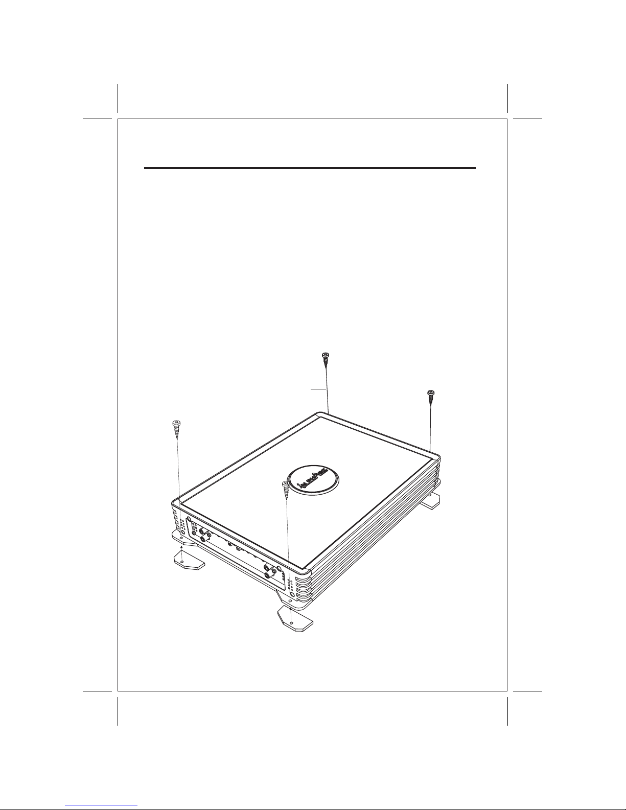
INSTALLATION
1. After reading precaution, decide where you are going to install the unit. Also, see Fig.1.
2. Once the location has been determined, place the amplifier into position. Using a felt tip
pen or pencil mark the four holes to be drilled for mounting. NEVER use the amplifier as
a template for drilling. It is very easy to damage the amplifier surface in this manner.
3. Remove amplifier. Drill four 3.5 m/m holes into mounting surface. If you want to mount
4. If possible, test the system to ensure it is operating correctly before final mounting of
5.
INSTALLATION DIAGRAM
MOUNTING:
Mount the amplifier using the supplied 4 self tapping screws.
the amplifier to MDF or wood panel, drill four 3.0m/m diameter holes into mounting surface.
the amplifier.
FIG.1
SELF TAP SCREWS
ON
PROT
POWER
GNDB+ REM
SPEAKER
FUSE
ON
PROT
POWER
GNDB+ REM
SPEAKER
FUSE
Features
- Fully 1 Ohm Stable Operation
- Class" D " Technology
- Military Spec Audiophile Grade Components
- High Efficiency PWM Power Supply - Multi-stranded power torroid
- Two toroidal cores
- MOSFET transistors
- Over sized Capacitor Banks
- Discrete Mount Power and Speaker Terminals
- Variable Lowpass Electronic Crossover
- Variable Subsonic Filter
- RCA Line Output
- 3Way Protection Circuitry(Thermal, Shot, Overload)
- Soft Remote On/Off Circuitry
- Digital Subwoofer Level Control
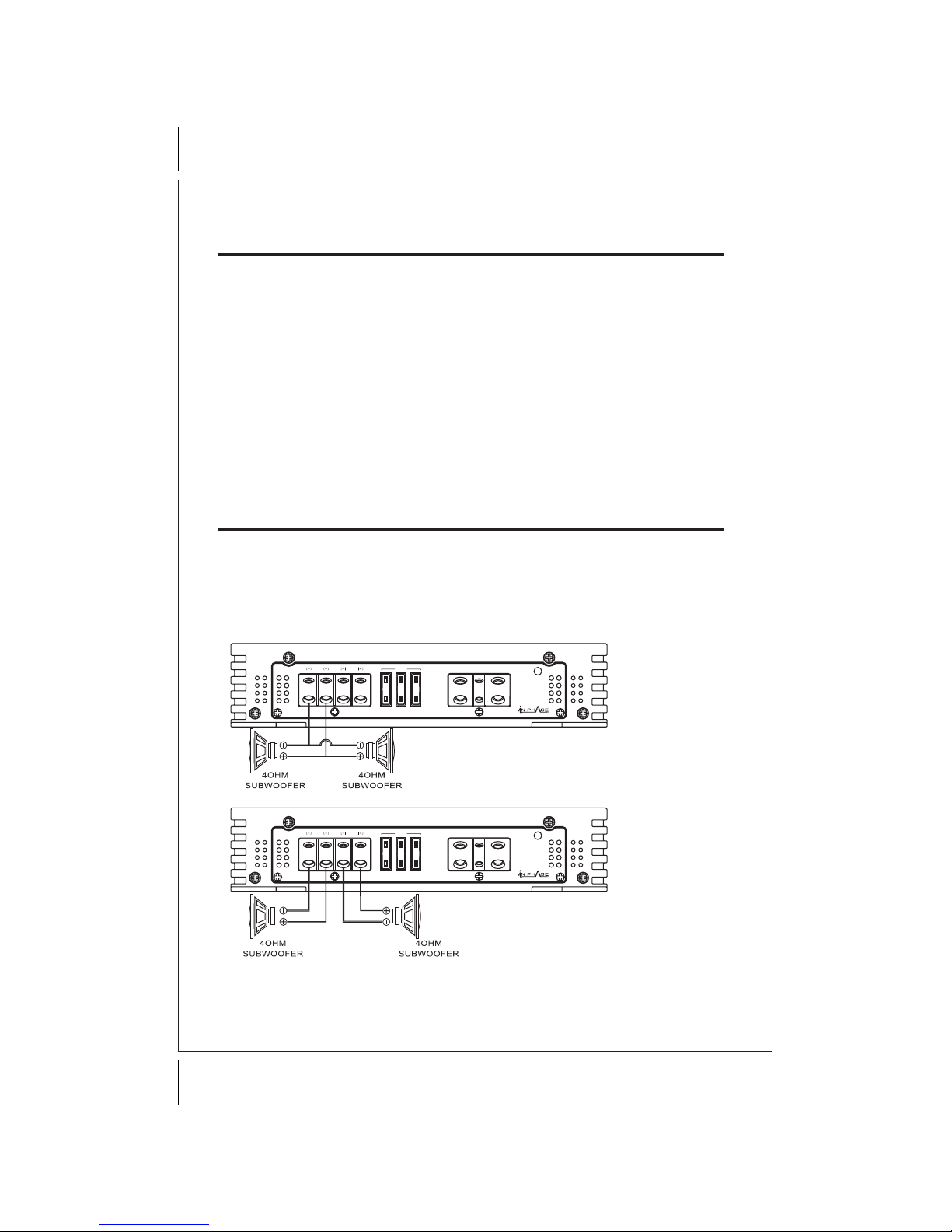
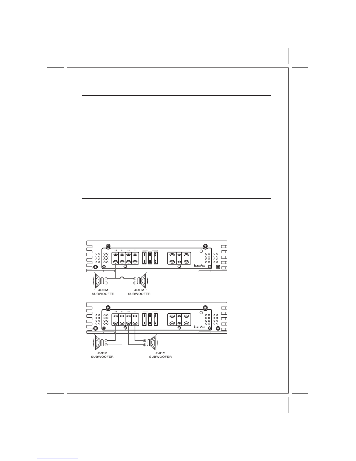
Speaker Wiring
The 2001D/4001D is a SINGLE CHANNEL dedicated subwoofer amplifier.
Unlike other amplifiers, the 2001D/4001D operates as a single channel and cannot be bridged.
Don't be fooled by the outputs. Two outputs are used strictly for convenience and are parallelled
internally on the amplifier. This means that if both outputs are used with one driver each, the
amplifier sees the same load as if the two same drivers are connected to only one output terminal.
See diagram below.
In both diagrams, the amplifier sees a 2 Ohm load.
4

Bridged Mono Wiring
FROM
RADIO
FROM REMOTE
GAIN CONTROL
5
< MASTER >
< SLAVE >
L
R
L
R
LINE INLINE OUT
MIN
LEVEL SUBSONIC
15HzMAX
BASS
BOOST
0dB50Hz 250Hz50Hz
L.P.F
12dB
PHASE
0
180
REMOTE
SLAVEMASTER
OUT
IN
MASTER/SLAVE
ON
PROT
POWER
GNDB+ REM
SPEAKER
FUSE
ON
PROT
POWER
GNDB+ REM
SPEAKER
FUSE
L
R
L
R
LINE INLINE OUT
MIN
LEVEL SUBSONIC
15HzMAX
BASS
BOOST
0dB50Hz 250Hz50Hz
L.P.F
12dB
PHASE
0
180
REMOTE
SLAVEMASTER
OUT
IN
MASTER/SLAVE
2 OHM

The proper wire size is very important for an amplifier of this power level. Because the
Class "D" amplifier is capable of drawing in excess of 90 amperes,4 gauge wire is
recommended for lengths up to twenty feet. if a longer length is needed, a larger gauge
Amplifier power wire should be wired directly to the battery using the wire requirements
listed above. Start at the amplifier and run the power wire through the vehicle to the
battery. The use of grommets is recommended when passing the power wire through
any metal wall. Avoid sharp corners or sharp body parts that may easily cut through the
insulation on the wire. Avoid running the power wire over engine components and near
heater cores. Use an inline fuse to eliminate the risk of a fire caused by a short in your
power wire. Connect the fuse holder as close to the battery positive as possible. For
most applications, an 80 ampere Maxi fuse or comparable ANL wafer fuse can be used.
Now connect the wire to the battery, but remember to leave the fuse out until all other
POWER SUPPLY CONNECTIONS
RECOMMENDED POWER WIRE
POWER
The Class "D" amplifier is designed to work within 10 to 16 volts DC. Before any wires
are connected, the vehicle's electrical system should be checked for correct voltage
supply with the help of a voltmeter. First check the voltage at the battery terminals with
the ignition in the off position. The voltmeter should read no less than 12 volts. Next,
check the battery with the engine running between 1500 and 2000 rpm. The voltmeter
should now read between 13.5 and 14.5 volts. If your vehicle's electrical system Is not
up to these specifications, we recommend having it checked by an automotive mechanic
before further installation.
wire may be necessary.
wire connections are mode.
When grounding your amplifier, locate a metal area close to the amplifier that is a good
source of ground ( preferably the floor ).Once again, investigate the area you wish to use
for electrical wires, vacuum lines, and brake or fuel lines. Using either a wire brush or
sandpaper eliminate unwanted paint to supply a better contact for your ground. Use the
same gauge wire for ground as you did for the power. Terminate the ground wire using the
correct size ring terminal and attach it to the bare metal using a nut and bolt. It is important
for this connection to be solid. To complete the job, spread silicon over the screw and bare
GROUND
REMOTE TURN-ON
metal to prevent rust and possible water leaks.
In between the power and ground is a remote turn-on terminal. This terminal must be
connected to a switched +12volt source. Typically, remote turn-on leads are provided
at the source unit that will turn on and off the amplifier in correspondence with the source.
If a radio does not have a remote turn-on, then a power antenna wire may be used. Yet, if
neither of these leads are available at the source, a switched +12 volt supply must be
supplied. Run a minimum of 18-gauge wire from the amplifier location to the source of the
switched +12 volt lead. If possible, route this wire on the same side of the vehicle as your
power wire. Connect the source remote output wire to the REM terminal on the amplifier
using a 3mm screw key. Cut the remote wire to length. Strip approximately 1/2 inch of
insulation from the end of the wire and insert into the terminal. Tighten the screw securely.
6

L
R
L
R
LINE INLINE OUT
MIN
LEVEL SUBSONIC
15HzMAX
BASS
BOOST
0dB50Hz 250Hz50Hz
L.P.F
12dB
PHASE
0
180
REMOTE
SLAVEMASTER
OUT
IN
MASTER/SLAVE
1. RCA Input Jacks 2. Input Level Control 3. Low Pass Frequency
4. Subsonic Filter 5. Bass Boost Control 6. Phase Control
7. Remote Control Jack 8. Master/Slave Switch 9. Slave Input Jack
CONTROL AND CROSSOVER
OPERATION
1. RCA Input Jacks- Low level-high impedance inputs.
U se high quality RCA cables designed for mobile applications.
2. Input Level Control- Adjust the input level for the marked channels.
T urn clockwise to increase the level, counterclockwise to decrease.
Amplifiers will run cooler and produce less system noise at lower level settings.
3. Low Pass Frequency- Adjust the crossover frequency by turning clockwise to set
to a higher f requency, counterclockwise to set to a lower frequency.
4 . Subsonic Filter Frequency- Adjust the subsonic filter frequency by turning clockwise
to set to a higher frequency, counterclockwise to set to a lower frequency.
5 . The Bass Boost control is used for a1-12dB Gain at 45Hz for extra bass punch.
6. Phase Control- Adjust the relative phase of the output a range of 0 to - 1 80 degrees
for solid bass r esponse and accurate imaging.
7. Remote Control Jack- For connecting the remote control module to the amplifier.
8. Master/Slave Switch- Select the remote level control or the on-board level control
as the master control.
9. Slave Input Jack- Used to connect to another amplifier when bridging 2 amps together.
T he Slave mode bypasses normal input jacks and controls.
7

This section provides you with a catalog of amplifier symptoms and their probable causes
and solutions. Before you consult this listing, make sure the vehicle's electrical system is
working properly by verifying that other electrical items (e. g. headlights, windows, etc.)
Still function correctly.
TROUBLE SHOOTING GUIDE.
No Audio
Low or N.C Remote
Turn-on connections
Blown Fuse
Power wires not connected
Blown or non speakers
connected
Check remote turn-on voltage at
amp and head unit
Replace with new fast-blow fuse
Check butt splices or solder joints
Check ground and battery
connections
Use VOM or DVM to measure speaker
coil
impedance; check speaker wiring
connections
SOLUTIONPROBABLE CAUSE
SYMPTOM
See adjustment procedure and check
each step;
Inspect each speaker for damage
and repair or replace suspected
component
Refer to head unit owner's manual
Input Sensitivity not set
properly
or damaged speaker cones
Low turn-on voltage
Distorted Audio
Audio Level Low Mute circuit on head
unit is on.
Check electrical system for low
voltage;
Check ground connection
Audio Lacks
Speakers wired with wrong
polarity, causing
cancellation of bass
frequencies
Check polarity of wires from
amplifiers to each speaker as defined
by the system design
Check battery voltage at amplifier
during operation
External Fuse
Blowing
Incorrect wiring or short
circuit
Refer to electrical installation and
check each installation step
Whining noise
on audio with
engine running
Amplifier is picking
up alternator noise
Install an in-line noise filter on the
head unit's power wire; Check
alternator routing diodes or voltage
regulator for proper operation. Check
all grounds , battery voltage, and
RCA cables
Ticking noise on
audio with
engine
running
Amplifier is picking up
radiated spark noise
Check RCA audio cable; Install an
in-line noise filter on the head unit's
power wire. Check spark plug wires.
8


Features and Specifications of the products described or illustrated in this manual are correct at the time of the printing but could change as production
changes occur without notice. In Phase, XT and 'In Life In Tune' are registered Trademarks of In Phase International Ltd, unless otherwise stated. No part
of this production may be reproduced without written permission from In Phase International Ltd. All Images and designs are the Intellectual Property of
In Phase International Ltd 2008
www.inphaseaudio.co.uk

IPA 2001D IPA 4001D
Bedienungsanleitung
Fur beste Leistung und sicheren Betrieb befolgen
Sie bitte alle Hinweise in dieser Bedienungsanleitung.
Bitte bewahren Sie die Bedienungsanleitung fur
spateres Nachschlagen auf.


IPA 2001D IPA 4001D
4000W
1200W x 1
2300W x 1
4000W x 1
90%
79%
10Hz - 250Hz
>100dB
200
200mV-6V
22k Ohm
250 x 55.5 x 480
50Hz-250Hz@24dB
15Hz - 50Hz@24dB
entfällt
MODELL
2000W
800W x 1
1200W x 1
2000W x 1
90%
79%
10Hz - 250Hz
>100dB
200
200mV-6V
22k Ohm
250 x 55.5 x 320
50Hz-250Hz@24dB
25A x 3
15Hz - 50Hz@24dB
SPEZIFIKATIONEN
Max. Ausgangsleistung
4 Ohm kont. Ausgangsleistung
2 Ohm kont. Ausgangsleistung
1 Ohm kont. Ausgangsleistung
Effizienz / typisch bei 4 Ohm
Min Rate bei 1 Ohm
Bandbreite ± 1dB
Rauschabstand
Dämpfungsfaktor
Eingangsempfindlichkeit
Eingangsimpedanz
Abmessungen (B x H x T) mm
Tiefpass-Filter (variabel)
Sicherungen
Subsonic-Filter (variabel)
Spezifikationen für 14,4 Volt Gleichspannung.
1

Herzlichen Glückwunsch zu Ihrem Kauf
Ihr neuer Hi-Fi überbrückbarer/Stereo Verstärker ist für bestes Klangerlebnis mit einer einjährigen
Garantie konzipiert. Bitte nehmen Sie sich einen Moment Zeit, um diese Bedienungsanleitung
aufmerksam durchzulesen. Hier werden Ausstattung und Bedienung des Geräts erklärt, um eine
problemlose Installation zu gewährleisten.
Allgemeine Sicherheitshinweise
2
Reparieren Sie das Gerät nicht selbst, das führt zum Verlust Ihrer Garantieansprüche.
Modifizieren Sie das Gerät nicht, das führt zum Verlust Ihrer Garantieansprüche.
Die Garantie verfällt ebenfalls bei Schäden, welche durch unsachgemäße Handhabung
oder Missachtung der Sicherheitshinweise entstehen. IN PHASE übernimmt keine
Haftung für Verletzungen aufgrund Missachtung der Sicherheitshinweise und
Warnungen. Der Ausschluss gilt ebenfalls für Folgeschäden.
Bei Rückgabe des Geräts benutzen Sie bitte die Original-Verpackung, um Schäden zu vermeiden
- Lesen Sie vor Benutzung des Geräts stets die Sicherheitshinweise.
- Bewahren Sie die Bedienungsanleitung für jeden Nutzer zugänglich auf.
- Benutzen Sie das Gerät in Fahrzeug und nicht in feuchten Umgebungen.
- Berühren Sie die Gerätestecker nicht mit nassen Händen.
- Anschlusskabel dürfen nur von einem autorisierten Kundendienst repariert werden.
- Ziehen Sie bei Gewitter oder wenn Sie das Geräte für einen längeren Zeitraum nicht benutzen
stets den Netzstecker.
- Beim Ziehen eines Gerätesteckers fassen Sie bitte nur am Stecker an, nicht am Kabel ziehen.
- Installieren Sie das Gerät mit ausreichender Ventilation zur Kühlung.
- Gerät nicht in unmittelbarer Umgebung von Wärmequellen oder in direkter Sonneneinstrahlung
montieren.
- Keine Fremdkörper in das Gerät einführen und keine Flüssigkeiten darauf verschütten.
- Reinigen Sie das Gerät nur mit einem feuchten Tuch. Benutzen Sie keine Reinigungs- oder
Lösungsmittel!
- Das Gerät enthält keine vom Verbraucher wartbaren Teile, nehmen Sie keine anderen
Einstellungen vor, als in dieser Bedienungsanleitung beschrieben.
- Ein defektes Gerät muss von einem IN PHASE autorisierten Kundendienst repariert werden.
- Bewahren Sie das Gerät kindersicher auf.

INSTALLATION
3
Abb.1
Blechschrauben
MONTAGE:
1. Nach dem Lesen der Sicherheitshinweise entscheiden Sie sich zunächst für einen Einbauort,
siehe Abb. 1.
2. Anschließend bringen Sie den Verstärker in Position. Markieren Sie die vier Bohrlöcher zur
Montage. Benutzen Sie KEINESFALLS den Verstärker als Bohrvorlage, damit können Sie leicht
die Oberfläche beschädigen.
3. Nehmen Sie den Verstärker wieder heraus und bohren Sie vier 3,5 mm Löcher in die
Montagefläche. Erfolgt die Montage auf MDF oder Holz, so bohren Sie vier 3,0 mm Löcher.
4. Testen Sie das System vor der endgültigen Montage.
5. Montieren Sie den Verstärker mit den vier mitgelieferten Blechschrauben.
INSTALLATIONS-DIAGRAMM
ON
PROT
POWER
GNDB+ REM
SPEAKER
FUSE
ON
PROT
POWER
GNDB+ REM
SPEAKER
FUSE
4
Ausstattung
- Voller 1 Ohm stabiler Betrieb
- Klasse D Technologie
- Audio-Komponenten gemäß Militäranforderungen
- Hochleistungs-PWM Spannungsversorgung - mehradriger Ringkern
- Zwei Ringkerne
- MOSFET Transistoren
- Überdimensionierte Kondensatorbatterien
- Separate Spannungs- und Lautsprecheranschlüsse
- Variabler Tiefpass Electronic-Crossover
- Variabler Subsonic-Filter
- Cinch (RCA) Line Ausgang
- 3-Wege Schutzschaltung (thermisch, Kurzschluss, Überlastung)
- Soft Start/Stop Schaltung
- Digitale Subwoofer Levelsteuerung
Lautsprecher-Verkabelung
Der 2001D/4001D ist ein EIN-KANAL dedizierter Subwoofer-Verstärker. Abweichend von anderen
Verstärkern arbeitet der 2001D/4001D als Ein-Kanal und kann nicht überbrückt werden. Lassen
Sie sich nicht von den Ausgängen verwirren. Zwei Ausgänge werden nur zur Bequemlichkeit
angeboten und sind intern im Verstärker parallel geschaltet. Das bedeutet, dass bei Benutzung
beider Ausgänge mit jeweils einem Lautsprecher der Verstärker die gleiche Last hat, wie mit zwei
gleichen Lautsprechern auf einem Ausgang. Siehe nachstehendes Diagramm.
In beiden Diagrammen ist die Last 2 Ohm.

VOM
RADIO
VON FERNGAIN
CONTROL
5
Überbrückbare Mono-Verkabelung
L
R
L
R
LINE INLINE OUT
MIN
LEVEL SUBSONIC
15HzMAX
BASS
BOOST
0dB50Hz 250Hz50Hz
L.P.F
12dB
PHASE
0
180
REMOTE
SLAVEMASTER
OUT
IN
MASTER/SLAVE
ON
PROT
POWER
GNDB+ REM
SPEAKER
FUSE
ON
PROT
POWER
GNDB+ REM
SPEAKER
FUSE
L
R
L
R
LINE INLINE OUT
MIN
LEVEL SUBSONIC
15HzMAX
BASS
BOOST
0dB50Hz 250Hz50Hz
L.P.F
12dB
PHASE
0
180
REMOTE
SLAVEMASTER
OUT
IN
MASTER/SLAVE
2 OHM
< MASTER >
< SLAVE >

6
SPANNUNGSVERSORGUNG
Der Klasse D Verstärker arbeitet mit einer Spannungsversorgung von 10 bis 16 Volt Gleichstrom.
Vor Anschluss an das Fahrzeugsystem überprüfen Sie bitte das elektrische System mit Hilfe eines
Voltmeters. Prüfen Sie zunächst die Batteriespannung bei ausgeschalteter Zündung, sie sollte
wenigstens 12 Volt betragen. Prüfen Sie nun die Batterie bei laufendem Motor mit 1500 bis
2000 U/min. Die Ablesung sollte 13,5 bis 14,5 Volt betragen. Entspricht Ihr Fahrzeug nicht diesen
Anforderungen, so lassen Sie es bitte vor Installation in einer Werkstatt überprüfen.
EMPFOHLENE STROMKABEL
Der korrekte Kabelquerschnitt ist für einen Verstärker dieser Leistungsklasse von höchster
Bedeutung. Klasse D Verstärker können über 90 Ampere ziehen, daher wird 4-Gauge Kabel bei
Längen bis zu 6 m empfohlen. Bei längeren Kabeln werden möglicherweise größere Querschnitte
benötigt.
STROM
Das Stromkabel muss direkt an der Batterie angeschlossen sein. Beginnen Sie am Verstärker und
verlegen Sie es zur Batterie. Benutzen Sie Kabeltüllen bei Metalldurchführungen. Vermeiden Sie
scharfe Ecken und Kanten, welche die Isolierung beschädigen könnten. Führen Sie das Kabel nicht
über den Motor oder in unmittelbarer Umgebung von Wäremequellen. Benutzen Sie eine
Inline-Sicherung so dicht wie möglich an der Batterie. In den meisten Fällen ist eine 80 Ampere Maxi
Sicherung oder eine vergleichbare ANL Halbleitersicherung ausreichend. Schließen Sie den
Sicherungshalter an der Fahrzeugbatterie an, setzen Sie aber noch nicht die Sicherung ein.
MASSE
Finden Sie einen Massenpunkt am Chassis, wo Sie den Verstärker anschließen können.
Die Oberfläche muss farb- und schmutzfrei sein. Dies können Sie mit einem kleinen Schleifaufsatz,
Sandpapier oder einem Drahtbürstenaufsatz erreichen. Befestigen Sie das Erdungskabel durch
Löten oder mit einem Klemmring. Bohren Sie das vorbereitete Chassis zum Anbolzen des
Erdungsringanschlusses mit Mutter, Bolzen und Unterlegscheiben an. Isolieren Sie Metall und
Anschluss mit Farbe oder Silikon gegen Rost und Oxidation. Silikon ist auch hervorragend geeignet,
um Muttern und Bolzen in den harten Bedingungen im Fahrzeug am Lösen zu hindern.
FERNEINSCHALTUNG
Zwischen dem Strom- und Masseanschluss befindet sich der Anschluss für die Ferneinschaltung.
Dieser Anschluss muss an einer geschalteten 12 Volt Quelle angeschlossen sein. Schließen Sie das
Fernsteuerungskabel (Motorantenne-Ausgang) des Hauptgeräts am Fernsteuerungskabel des
Verstärkers an. Ist das Hauptgerät nicht mit einem Fernsteuerungs-/Antennen-Ausgang ausgestattet,
so finden Sie ein Kabel, welches über die ACC Funktion der Zündung eingeschaltet wird, benutzen
Sie wenigstens ein 18-Gauge Kabel. Verlegen Sie dieses Kabel auf der gleichen Seite wie das
Stromkabel und schließen Sie es am REM Anschluss mit einem 3 mm Schraubenschlüssel an.
Isolieren Sie etwa 10-15 mm des Kabels ab.

1. Cinch (RCA) Buchsen 2. Eingangslevel-Steuerung 3. Tiefpass-Frequenz
4. Subsonic-Filter 5. Bass Boost 6. Phasensteuerung
7. Fernanschluss 8. Master/Slave Umschalter 9. Slave Anschlussbuchse
L
R
L
R
LINE INLINE OUT
MIN
LEVEL SUBSONIC
15HzMAX
BASS
BOOST
0dB50Hz 250Hz50Hz
L.P.F
12dB
PHASE
0
180
REMOTE
SLAVEMASTER
OUT
IN
MASTER/SLAVE
7
BEDIENUNGSHINWEISE
STEUERUNG UND CROSSOVER
1. RCA Eingänge Low-Level Eingänge mit hoher Impedanz. Benutzen Sie hochwertige RCA Kabel
für Fahrzeugeinbau.
2. Eingangslevel-Steuerung Stellen Sie den Eingangslevel für die markierten Kanäle ein.
Rechtsdrehung zur Erhöhung des Levels, Linksdrehung zur Verringerung. Mit geringeren Level Einstellungen laufen Verstärker kühler und entwickeln weniger Systemgeräusche.
3. Tiefpass-Frequenz Stellen Sie die Crossover-Frequenz nach rechts für eine höhere Frequenz ein,
nach links für eine tiefere Frequenz.
4. Subsonic-Filter Frequenz Stellen Sie die Subsonic-Filter Frequenz nach rechts für eine höhere
Frequenz ein, nach links für eine tiefere Frequenz.
5. Die Bass Boost Steuerung wird für 1-12dB Gain bei 45Hz für extra Bässe benutzt.
6. Phasensteuerung Stellen Sie die relative Phase des Ausgangs für einen Bereich zwischen 0 bis
180 Grad für starke Bassansprache und genaue Abbildung ein.
7. Fernanschluss Zum Anschluss des Fernsteuerungsmoduls am Verstärker.
8. Master/Slave Umschalter Wählen Sie Fern-Levelsteuerung oder die On-board Levelsteuerung
als Master Control.
9. Slave Anschluss Anschluss eines weiteren Verstärkers bei der Zusammenschaltung von 2
Verstärkern. Der Slavemodus umgeht die normalen Eingänge und Steuerungen.

8
SYMPTOM
Dieser Abschnitt gibt Ihnen eine Reihe von Verstärkersymptomen und deren mögliche
Ursachen sowie Lösungsvorschläge. Bevor Sie hier um Rat suchen vergewissern Sie sich
bitte, dass das elektrische System Ihres Fahrzeugs ordnungsgemäß funktioniert
(überprüfen Sie beispielsweise Scheinwerfer, Fensterheber usw.).
Störungserkennung
Klickgeräusche bei
laufendem Motor
Prüfen Sie die Spannung der Ferneinschaltung am
Verstärker und am Hauptgerät
Ersetzen Sie die Sicherungen
Prüfen Sie Ihre Anschlüsse
Prüfen Sie Masse- und Batterieanschluss
Prüfen Sie mit VOM oder DVM Impedanz der
Lautsprecherspule
Prüfen Sie die Lautsprecher-Verkabelung
Kein Ton
Geringe oder keine Spannung auf
Fernbedienungskabel
Sicherung durchgebrannt
Stromkabel nicht angeschlossen
Lautsprecher durchgebrannt oder
nicht angeschlossen
Verzerrter Ton
Eingangsempfindlichkeit nicht
korrekt eingestellt oder
beschädigte Lautsprecher-Cones
Geringe Einschaltspannung
Siehe Einstellung und prüfen Sie die einzelnen
Schritte
Prüfen Sie die Lautsprecher auf Schäden und
reparieren oder tauschen Sie problematische
Komponenten aus
Siehe Bedienungsanleitung des Hauptgeräts
Geringer
Audioausgang
Stummer Schaltkreis des
Hauptgeräts
Prüfen Sie das elektrische System auf
Niederspannung
Prüfen Sie den Masseanschluss
Tonvolumen fehlt
Externe Sicherung
brennt durch
Heulgeräusche bei
laufendem Motor
Lautsprecherkabel verpolt, daher
keine Bassfrequenzen
Prüfen Sie die Polarität der Kabel vom Verstärker zu
allen Lautsprechern
Prüfen Sie die Batteriespannung am Verstärker
während des Betriebs
Falsche Verkabelung oder
Kurzschluss
Siehe elektrische Installation und überprüfen Sie alle
Schritte
Verstärker empfängt Geräusche
von der Lichtmaschine
Installieren Sie einen Inline Geräuschfilter im
Stromkabel des Hauptgeräts
Prüfen Sie die Routingdioden oder den Regler
Prüfen Sie alle Masse-, Strom- und Cinch (RCA)
Kabel
Prüfen Sie die Cinch (RCA) Kabel
Installieren Sie einen Inline Geräuschfilter im
Stromkabel des Hauptgeräts
Prüfen Sie die Zündkabel
Verstärker empfängt Geräusche
von den Zündkerzen
LÖSUNGSVORSCHLAGMÖGLICHE URSACHE


www.inphaseaudio.co.uk
Ausstattung und Spezifikationen der in dieser Bedienungsanleitung beschriebenen oder abgebildeten Produkte waren zum Zeitpunkt der Drucklegung korrekt,
können sich jedoch während der Produktion ohne Vorankündigung ändern. In Phase, XT und ‚In Life in Tune' sind eingetragene Marken von In Phase
International Ltd, sofern nicht gegenteilig angegeben. Kein Teil dieser Veröffentlichung darf ohne die ausdrückliche schriftliche Genehmigung durch In Phase
International Ltd reproduziert werden. Alle Abbildungen und Designs sind das geistige Eigentum von In Phase International Ltd 2008.

IPA 2001D IPA 4001D
Manuel d'instruction
Pour assurer une performance et une securite
maximale, veuillez suivre ce manuel. Veuillez
conserver le manuel pour vous y referez apres
l'installation.


Sortie Puissance Maximale
Sortie Electrique Cont. 4 ohms
Sortie Electrique Cont.2 ohms
Sortie Electrique Cont.1 ohm
Efficacité / Typique@ 4 ohms
Taux Min @ 1 Ohm
Largeur Bande ± 1dB
Signal de Ratio de Son
Facteur d'amortissement
Entrée sensibilité
Entrée Impédance
Dimensions (L x H x P) mm
Filtre Passe Bas (Variable)
Taux du fusible
Filtre subsonique (Variable)
IPA 2001D IPA 4001D
4000W
1200W x 1
2300W x 1
4000W x 1
90%
79%
10Hz - 250Hz
>100dB
200
200mV-6V
22k Ohm
250 x 55.5 x 480
50Hz-250Hz@24dB
N/A
15Hz - 50Hz@24dB
MODELE
2000W
800W x 1
1200W x 1
2000W x 1
90%
79%
10Hz - 250Hz
>100dB
200
200mV-6V
22k Ohm
250 x 55.5 x 320
50Hz-250Hz@24dB
25A x 3
15Hz - 50Hz@24dB
SPECIFICITES
Spécifications correspondant à une alimentation 14.4 volts DC.
1

2
Félicitations pour votre Acquisition
Votre nouvel amplificateur haute fidélité compatible/stéréo est conçu pour vous fournir un plaisir
maximal, et une année de service sans difficulté. Veuillez prendre un peu de temps pour
complètement lire le manuel. Il vous présentera les caractéristiques et l'utilisation de votre unité et
vous assurera une installation sans peine.
Instructions générales de sécurité
- Lisez toujours le guide de l'utilisateur avant d'utiliser l'équipement.
- Laissez le guide de l'utilisateur dans un endroit où tout le monde peut le lire.
- Utilisez l'équipement à l'intérieur d'un véhicule et jamais dans un environnement humide.
- Ne retirez jamais ni n'insérez une prise dans la prise murale avec des mains mouillées.
- Si la prise et/ou le câble et/ou l'entrée du câble est endommagé, il doit être réparé par un
professionnel.
- Retirez toujours la prise de la prise murale pendant un orage, ou si l'équipement n'est pas utilisé
pendantune longue période.
- Ne débranchez jamais la prise de la prise électrique en tirant sur le cordon.
- Installez l'équipement de manière à ce que un refroidissement suffisant soit possible.
- Ne placez jamais l'appareil proche de sources de chaleur ou exposé au soleil.
- Assurez-vous qu'il n'y a pas de petits objets ou de liquides qui peuvent se glisser dans l'appareil.
- Nettoyez l'appareil uniquement avec un chiffon sans poussière légèrement humide. N'utilisez pas
de produits nettoyants ou de produits chimiques !
- L'appareil ne contient pas de composant, autre que ceux mentionnés dans le guide de l'utilisateur,
pouvant être réparé ou remplacé par l'utilisateur.
- Si l'appareil est défaillant, il doit être réparé par des réparateurs qualifiés de la compagnie
In Phase.
- Tenez l'équipement hors de la porté des enfants.
N'effectuez aucune réparation sur l'équipement vous-même ; vous invalideriez alors la
garantie. La garantie est aussi invalide si des accidents ou endommagements quels qu'ils
soient sont causés par une utilisation incorrecte et/ou si vous n'avez pas tenu compte des
avertissements indiqués dans ce guide de l'utilisateur. IN PHASE n'accepte pas la
responsabilité d'un accident personnel qui serait la conséquence du non-respect des
instructions de sécurité et avertissements. Ceci est aussi le cas pour les pertes conséquentes
de quelque forme.
Veuillez conserver l'emballage en sécurité, en cas de défaillance du produit, veuillez le renvoyer
dans son emballage d'origine pour éviter de l'endommager plus.

INSTALLATION
3
ill.1
Vis auto taraudeuses
MONTAGE :
1. Après avoir lu les précautions, décidez de l'endroit ou vous allez installer l'unité. Voir l'ill. 1.
2. Une fois que l'emplacement a été déterminé, placez l'amplificateur en position. Utilisez
un feutre ou un crayon pour marquer les quatre trous à percer pour le montage. N'utilisez
JAMAIS l'amplificateur comme un gabarit pour percer. Il est alors facile d'endommager la
surface de l'amplificateur.
3. Enlevez l'amplificateur. Percez quatre trous de 3,5 mm de diamètre sur la surface de
montage. Si vous souhaitez monter l'amplificateur sur un MDF ou un panneau de bois,
percez quatre trous de 3,0 m/m de diamètre sur la surface de montage.
4. Si possible, testez le système pour assurer qu'il fonctionne correctement avant le montage
final de l'amplificateur.
5. Montez l'amplificateur en utilisant les 4 vis auto taraudeuses fournies.
SCHEMA D'INSTALLATION

ON
PROT
POWER
GNDB+ REM
SPEAKER
FUSE
ON
PROT
POWER
GNDB+ REM
SPEAKER
FUSE
4
Le 2001D/4001D est un amplificateur de haut-parleur d'aigus dédié à CANAL SIMPLE.
Contrairement à d'autres amplificateurs, le 2001D/4001D fonctionne comme un canal simple et ne
peut être compatible. Ne vous trompez pas de sortie. Deux sorties sont utilisées uniquement pour
votre convenance et sont mises en parallèle à l'intérieur de l'appareil. Cela signifie que si les deux
sorties sont utilisées avec un driver chacune, l'amplificateur reconnaît la même charge que si les
deux drivers étaient connectés à un même terminal de sortie. Voir le schéma ci-dessous.
Caractéristiques
- Fonctionnement stable complet Ohm
- Technologie Classe " D "
- Components de Niveau Audiophile Spécifications Militaires
- Alimentation électrique PWM Haute Efficacité Alimentation à tore bobiné multi isolé
- Deux noyaux à tore bobiné
- Transistor MOSFET
- Batterie à surcapacité
- Terminaux d'Alimentation et d'Enceinte Distincts
- Séparateur Electronique Passe Bas Variable
- Filtre Subsonique Variable
- Sortie de ligne RCA
- 3 Protections de circuit (thermique, court-circuit et surcharge)
- Eteindre/Allumer les circuits à distance (soft ?)
- Circuit des fils avec Niveau de Contrôle du Haut-Parleur d'Aigus
HAUT-PARLEUR D'AIGUS 4 OHM
Câblage d'orateur
HAUT-PARLEUR D'AIGUS 4 OHM
Dans les deux schémas, l'amplificateur reçoit une charge de 2 ohm.

5
DU
CONTROLE
DE GAIN A
DISTANCE
DE LA
RADIO
< MAITRE >
< ESCLAVE >
Circuit de fils Mono Multipliable
L
R
L
R
LINE INLINE OUT
MIN
LEVEL SUBSONIC
15HzMAX
BASS
BOOST
0dB50Hz 250Hz50Hz
L.P.F
12dB
PHASE
0
180
REMOTE
SLAVEMASTER
OUT
IN
MASTER/SLAVE
ON
PROT
POWER
GNDB+ REM
SPEAKER
FUSE
ON
PROT
POWER
GNDB+ REM
SPEAKER
FUSE
L
R
L
R
LINE INLINE OUT
MIN
LEVEL SUBSONIC
15HzMAX
BASS
BOOST
0dB50Hz 250Hz50Hz
L.P.F
12dB
PHASE
0
180
REMOTE
SLAVEMASTER
OUT
IN
MASTER/SLAVE
2 OHM

6
CONNEXIONS DE L'ALIMENTATION ELECTRIQUE
L'amplificateur Classe "D" est conçu pour fonctionner entre 10 et 16 Volts. Avant qu'aucun fil ne soit
connecté, vérifiez la tension du système électrique du véhicule à l'aide d'un voltmètre. Vérifiez
d'abord le voltage aux terminaux de la batterie sans le contact. Le voltmètre doit lire une tension
supérieure à 12 volts. Puis, vérifiez que lorsque le contact est mis, la batterie fonctionne entre 1500
et 2000 rpm. Le voltmètre doit maintenant lire entre 13,5 et 14,5 volts. Si le système de votre
véhicule ne correspond pas à ces spécifications, nous vous recommandons de le faire vérifier par un
mécanicien automobile avant l'installation.
CORDON D'ALIMENTATION RECOMMANDE
La taille du cordon est très important pour un amplificateur de cette puissance.
Parce que l'amplificateur Classe "D" est capable de sur extraire 90 ampères, un cordon de 4 jauges
est recommandé afin de l'allonger de 20 pieds. Si vous avez besoin d'un plus long cordon, un fil
d'une jauge plus important peut être nécessaire.
ALIMENTATION
Le cordon d'alimentation de l'amplificateur doit être connecté directement à la batterie en respectant
les préalables listés auparavant. Partez de l'amplificateur et faites courir le cordon d 'alimentation par
la batterie du véhicule. L'utilisation de gommettes est recommandée lorsque vous faites passer le
cordon d'alimentation par des parois métallisées. Evitez les coins coupants ou les parties coupantes
du corps qui pourraient facilement couper l'isolation du fil. Evitez de faire passer le cordon
d'alimentation sur des composants du moteur ou prés des noyaux de chaleur. Utilisez un fusible
pour éliminer le risque d'incendie causé par un court circuit sur votre cordon d'alimentation.
Connectez le boîtier du fusible aussi près du pole positif de la batterie que possible. Pour la plupart
des applications, un fusible de maximum 80 ampères ou un fusible mince ANL comparable peut être
utilisé. Connectez maintenant le cordon à la batterie, mais souvenez-vous de laisser le fusible dehors
jusqu'à ce que toutes les connexions de fils soient effectuées.
PRISE DE TERRE
Lorsque vous reliez votre amplificateur à la terre, localisez un espace métallique proche de
l'amplificateur qui sera une bonne source de terre (si possible le sol). Une fois encore, vérifiez que
l'espace que vous souhaitez utiliser ne comporte pas de fils électriques, de circuits à vide, de freins
ou de tuyaux de carburant. Utilisez une brosse à fil ou du papier de verre pour éliminer la peinture
et permettre un meilleur contact à la terre. Utilisez un cordon de la même taille pour la terre et pour
l'alimentation. Terminez le fil de terre en utilisant un terminal en anneau de la bonne taille et
attachez-le à la barre en métal en utilisant un écrou et un boulon. Il est important que la connexion
soit solide. Pour achever le travail, répandez de la silicone sur la vis et la barre en métal pour éviter
la rouille et les fuites d'eau possibles.
ALLUMAGE A DISTANCE
Entre l'alimentation et la prise de terre, il y a un terminal d'alimentation à distance. Ce terminal doit
être connecté à un interrupteur +12volt. Généralement, les fils d'allumage à distance sont fournis par
l'unité source qui éteint ou allume l'amplificateur en même temps qu'elle s'éteint ou s'allume. Si la
radio n'a pas d'allumage à distance, vous pouvez utiliser un fil d'alimentation d'antenne. Si aucun de
ces fils n'est disponible à la source, un interrupteur +12V doit être fourni. Faites passer un fil d'au
minimum 18 jauges de l'amplificateur jusqu'à la source du fil de l'interrupteur +12V. Si possible,
faites passer ce fil du même coté de votre véhicule que le cordon d'alimentation. Connectez le fil de
sortie à distance de la source au terminal REM de l'amplificateur en utilisant un tournevis 3mm.
Coupez le fil à distance à la longueur. Enlevez environ ½ pouce d'isolation à partir de l'extrémité du
fil et insérez au terminal. Serrez sûrement la vis.

L
R
L
R
LINE INLINE OUT
MIN
LEVEL SUBSONIC
15HzMAX
BASS
BOOST
0dB50Hz 250Hz50Hz
L.P.F
12dB
PHASE
0
180
REMOTE
SLAVEMASTER
OUT
IN
MASTER/SLAVE
7
CONTROLE ET SEPARATEUR
1. Jacks d'entrée RCA Entrées Bas niveau Haute impédance. Utilisez des câbles RCA de haute
qualité conçus pour des applications mobiles.
2. Contrôle de niveau d'entrée Ajuste le niveau d'entrée de certains canaux marqués. Tournez
dans les sens des aiguilles d'une montre pour augmenter le niveau, et dans le sens inverse pour
baisser. Les amplificateurs se refroidiront et produiront moins de bruit de système s'ils sont réglés
à un niveau plus bas.
3. Fréquence Passe Bas Ajustez la fréquence du séparateur en tournant dans le sens des aiguilles
d'une montre pour une fréquence plus haute, et dans le sens inverse pour régler une fréquence
basse.
4. Filtre de fréquence subsonique Ajustez la fréquence du Filtre de fréquence subsonique en
tournant dans le sens des aiguilles d'une montre pour une fréquence plus haute, et dans le sens
inverse pour régler une fréquence basse.
5. Le contrôle de Boost de Basse est utilisé pour un gain de basse de 1-12 dB à 45 Hz.
6. Contrôle de Phase Ajuste la phrase relative de la sortie d'une gamme de 0 à 180 degrés pour
une réponse de basse solide et une imagerie correcte.
7. Jack de la Commande à distance Pour connecter un module de commande à distance sur
l'amplificateur.
8. Interrupteur Maître/ Esclave Sélectionnez le contrôle de commande à distance ou le contrôle de
niveau à bord comme le contrôle Maître.
9. Jack d'entrée Slave (Esclave) Utilisé pour connecter un autre amplificateur lorsque vous multipliez
deux amps ensemble. Le mode Slave contourne les jacks d'entrée normaux et les contrôles.
1.Jacks d'entrée RCA 2.Contrôle de Niveau d'entrée 3.Fréquence Passe Bas
4.Filtre subsonique 5.Contrôle de Boost de Basse 6.Contrôle de phase
7.Jack de contrôle à distance 8.Interrupteur Maître/Esclave 9.Jack d'entrée esclave
FONCTIONNEMENT

8
Cette section compile les symptômes de l'amplificateur, leurs causes et les solutions possibles.
Avant de consulter ce listing, assurez-vous que le système électrique de votre véhicule fonctionne
correctement en vérifiant que d'autres éléments électriques (par ex. Les phares, les fenêtres…etc.)
Fonctionnent.
Guide de Dépannage
SYMPTOME CAUSE PROBABLE SOLUTION
Pas de sortie
Audio
Distance basse ou N.C
Connexions allumées
Fusible sauté
Fils d'alimentation non connectés
Enceintes endommagées
Le produit n'est pas connecté
correctement
Vérifiez le voltage d'allumage à l'amp ou à
l'unité principale
Remplacez le fusible
Vérifiez les collages arrières et les joints de
soudure
Vérifiez les connexions à la terre et à la
batterie
Utilisez un VOM ou DVM pour mesurer
l'impédance de la bobine de l'enceinte;
Vérifiez les connexions des fils de
l'enceinte
Voir les procédures d'ajustement et vérifier
chaque étape ; inspectez les enceintes et
vérifiez les endommagements et
réparations.
Remplacez les composants
suspects. Référez-vous au manuel de
l'utilisateur de l'unité principale.
Sortie Audio
Altérée
L'Entrée Sensibilité n'est pas réglée
correctement ou les cônes des
enceintes sont endommagés.
Voltage d'allumage bas
Vérifiez que le système électrique est en
voltage bas ; vérifiez les connexions de
terre.
Vérifiez la polarité des fils des
amplificateurs à chaque enceinte comme
défini par la conception du système.
Vérifiez le voltage de la batterie à
l'amplificateur pendant l'utilisation.
Niveau Audio
Faible
La fonction Muet de l'unité principale
est activée.
Manque Audio
Les fils des enceintes ne respectent
pas la polarité, entraînant l'annulation
des fréquences basses.
Référez-vous à l'installation électrique et
vérifiez toutes les étapes d'installation.
Fusible externe
saute
Circuit incorrect ou court-circuit
Installez un filtre à bruit sur le fil
d'alimentation de l'unité principale; Vérifiez
les diodes de routage de l'alternateur ou le
régulateur de voltage pour une utilisation
correcte. Vérifiez tous les câbles de terre,
la tension de la batterie et les câbles RCA.
Bruit criard
quand l'engin
fonctionne
L'amplificateur absorbe les bruits de
l'alternateur
Vérifiez le câble audio RCA ; Installez un
filtre à bruit sur le fil d'alimentation de
l'unité principale. Vérifiez les fils des
bougies.
Bruit ralenti
quand l'engin
fonctionne
L'amplificateur absorbe les bruits
dégagés par les bougies


www.inphaseaudio.co.uk
Les caractéristiques et Spécifications des produits décrits ou illustrés dans ce manuel sont correctes au moment de la publication mais peuvent
changer si des changements de production sont effectués sans notice. In Phase, XT et In Life in Tune sont des Trademarks enregistrées de
In Phase International Ltd, sauf si indication contraire. Aucune partie de cette production ne doit être reproduite sans la permission écrite de
In Phase International Ltd. Toutes les images et les dessins sont la Propriété Intellectuelle de In Phase International Ltd 2008.

IPA 2001D IPA 4001D
Per assicurare le migliori prestazioni e la
massima sicurezza si prega di seguire il
presente manuale. Dopo l'installazione,
conservare il manuale per future consultazioni.
Manuale delle Istruzioni


IPA 2001D IPA 4001D
4000W
1200W x 1
2300W x 1
4000W x 1
90%
79%
10Hz - 250Hz
>100dB
200
200mV-6V
22k Ohm
250 x 55.5 x 480
50Hz-250Hz a 24dB
N.D.
15Hz - 50Hz a 24dB
MODELLO
2000W
800W x 1
1200W x 1
2000W x 1
90%
79%
10Hz - 250Hz
>100dB
200
200mV-6V
22k Ohm
250 x 55.5 x 320
50Hz-250Hz a 24dB
25A x 3
15Hz - 50Hz a 24dB
SPECIFICHE
Uscita alimentazione picco
Uscita potenza Cont. 4 ohm
Uscita potenza Cont. 2 ohm
Uscita potenza Cont. 1 ohm
Efficienza / Tipica a 4 ohm
Rate min. a 1 ohm
Larghezza di banda ± 1dB
Rapporto segnale-rumore
Fattore di smorzamento
Sensibilità ingresso
Impedenza ingresso
Dimensioni (L x H x P) mm
Filtro passa basso (variabile)
Fusibile
Filtro subsonico (variabile)
le specifiche sono con 14,4 volt DC.
1

2
Congratulazioni per l'acquisto
Questo amplificatore stereo/a ponte ad alta fedeltà è progettato per offrire le massime prestazioni e
un anno di servizio regolare. Si prega di dedicare qualche minuto alla lettura accurata di questo
manuale, che spiega le caratteristiche e il funzionamento dell'apparecchio e contribuisce ad
assicurarne l'installazione senza problemi.
Istruzioni relative alla sicurezza
- Leggere sempre la guida utente prima di utilizzare le apparecchiature.
- Conservare la guida utente in un luogo accessibile a tutti.
- Utilizzare l'apparecchio all'interno di veicoli e non in ambienti umidi.
- Non staccare o inserire la spina dalla presa con le mani bagnate.
- Se la spina e/o il cavo e/o l'ingresso del cavo dell'apparecchio sono danneggiati, devono essere
riparati da un professionista.
- Staccare sempre la spina dalla presa a muro sia durante i temporali sia quando l'apparecchio non
viene utilizzato per periodi prolungati.
- Non staccare mai la spina dalla presa tirando il cavo.
- Installare l'apparecchiatura in modo che ne sia possibile il sufficiente raffreddamento.
- Non utilizzare mai l'apparecchio in prossimità di sorgenti di calore e/o alla luce solare diretta.
- Assicurarsi che piccoli oggetti e liquidi non possano penetrare nell'apparecchio.
- Pulire l'apparecchio esclusivamente con un panno leggermente umido e pulito. Non utilizzare
detergenti o soluzioni per la pulizia!
- L'apparecchio non contiene componenti oltre a quelli indicati nella guida utente, che possano
essere riparati o sostituiti dall'utente.
- Se l'apparecchio è difettoso, deve essere riparato da un centro riparazioni qualificato IN PHASE.
- Tenere l'apparecchiatura fuori dalla portata dei bamb
Non effettuare nessun tipo di riparazione dell'apparecchiatura per proprio conto, pena
l'annullamento della garanzia. L'apparecchiatura, inoltre, non deve essere modificata, pena
l'annullamento della garanzia. La garanzia è resa nulla anche in caso di incidenti e danni di
qualsiasi tipo che risultino dall'uso improprio e/o, in generale, dal mancato rispetto delle
avvertenze contenute in questo manuale utente. IN PHASE declina ogni responsabilità per
qualsiasi danno personale che possa risultare dal mancato rispetto delle istruzioni e avvertenze
relative alla sicurezza. Questo vale anche per qualsiasi tipo di conseguente perdita.
Conservare con cura la confezione in modo che, in caso di guasto all'apparecchiatura, la si possa
restituire nella confezione originale per evitare che subisca danni.

3
FIG.1
INSTALLAZIONE
MONTAGGIO:
1. Dopo aver letto le precauzioni, decidere dove installare l'apparecchio. Vedere anche la Fig. 1.
2. Una volta che si è determinata la posizione, posizionare l'amplificatore. Utilizzando un pennarello
o una matita, segnare i punti corrispondenti ai quattro fori per il montaggio da effettuare con il
trapano. NON utilizzare MAI l'amplificatore stesso quando si usa il trapano. Se ne potrebbe
facilmente danneggiare l'involucro.
3. Rimuovere l'amplificatore. Effettuare quattro fori da 3,5 mm sulla superficie di montaggio. Se si
desidera montare l'amplificatore su un pannello in MDF o in legno, effettuare quattro fori da 3,0 mm
sulla superficie di montaggio.
4. Se possibile, testare il sistema per assicurarne il corretto funzionamento prima del montaggio
finale dell'amplificatore.
5. Montare l'amplificatore mediante le quattro viti autofilettanti fornite.
SCHEMA DI INSTALLAZIONE
VITI AUTOFILETTANTI

ON
PROT
POWER
GNDB+ REM
SPEAKER
FUSE
ON
PROT
POWER
GNDB+ REM
SPEAKER
FUSE
4
4OHM
SUBWOOFER
Caratteristiche
- Funzionamento a 1 ohm completamente stabile
- Tecnologia classe D
- Componenti audiofili spec. militari
- Alimentazione PWM ad alta efficienza Toroidale multifilamento
- Due nuclei toroidali
- Transistor MOSFET
- Banchi di condensatori sovradimensionati
- Terminali alimentazione e altoparlanti discreti
- Crossover elettronico passa-basso variabile
- Filtro subsonico variabile
- Uscita line RCA
- Circuiti di protezione a tre vie (termico, corto, sovraccarico)
- Circuito On/Off remoto soft
- Controllo digitale livello subwoofer
Cablaggio Altoparlanti
Il 2001D/4001D è un amplificatore per subwoofer dedicato a CANALE SINGOLO. A differenza di
altri amplificatori, il 2001D/4001D funziona come canale singolo e non può essere a ponte. Non ci si
faccia ingannare dalle uscite. Due uscite sono usate solamente per convenienza e sono messe in
parallelo all'interno sull'amplificatore. Ciò significa che se entrambe le uscite sono utilizzate con un
driver ognuna, l'amplificatore vede lo stesso carico come se i due stessi driver fossero collegati ad
un unico terminale di uscita. Si veda lo schema seguente.
In entrambi gli schemi, l'amplificatore rileva un carico da 2 ohm.
4OHM
SUBWOOFER
4OHM
SUBWOOFER
4OHM
SUBWOOFER

L
R
L
R
LINE INLINE OUT
MIN
LEVEL SUBSONIC
15HzMAX
BASS
BOOST
0dB50Hz 250Hz50Hz
L.P.F
12dB
PHASE
0
180
REMOTE
SLAVEMASTER
OUT
IN
MASTER/SLAVE
ON
PROT
POWER
GNDB+ REM
SPEAKER
FUSE
ON
PROT
POWER
GNDB+ REM
SPEAKER
FUSE
L
R
L
R
LINE INLINE OUT
MIN
LEVEL SUBSONIC
15HzMAX
BASS
BOOST
0dB50Hz 250Hz50Hz
L.P.F
12dB
PHASE
0
180
REMOTE
SLAVEMASTER
OUT
IN
MASTER/SLAVE
2 OHM
5
< MASTER >
< SLAVE >
Cablaggio mono predisposto a ponte
DA
CONTROLLO
GUADAGNO
REMOTO
DA
RADIO

6
COLLEGAMENTI ALIMENTAZIONE
L'amplificatore di classe D è progettato per funzionare entro 10-16 volt DC. Prima di collegare
qualsiasi cavo, è opportuno verificare con l'aiuto di un voltmetro che la tensione del sistema elettrico
del veicolo sia corretta. Verificare prima la tensione ai terminali della batteria con la chiave in
posizione spenta. Il voltmetro dovrebbe misurare almeno 12 volt. Quindi verificare la batteria con il
motore acceso tra 1500 e 2000 giri. Ora il voltmetro dovrebbe rilevare un valore compreso tra 13,5
e 14,5 volt. Se il sistema elettrico del veicolo non corrisponde a queste specifiche, si raccomanda di
farlo controllare da un meccanico prima di proseguire con l'installazione.
CAVO DI ALIMENTAZIONE RACCOMANDATO
Per un amplificatore di questa potenza, è molto importante che la dimensione del cavo sia
appropriata. Poiché l'amplificatore di classe D è in grado di assorbire oltre 90 ampere, si
raccomanda l'uso di cavi da 4 gauge per lunghezze fino a 6 metri. In caso di lunghezze superiori,
è necessario che lo spessore del cavo sia maggiore.
ALIMENTAZIONE
Il cavo di alimentazione dell'amplificatore va collegato direttamente alla batteria secondo i requisiti
sopra indicati. Iniziare all'amplificatore e disporre il cavo di alimentazione lungo il veicolo fino alla
batteria. Se il cavo viene fatto passato attraverso pareti di metallo si raccomanda l'uso di anelli di
tenuta. Evitare spigoli e parti taglienti della carrozzeria che potrebbero facilmente tagliare
l'isolamento del cavo. Evitare di disporre il cavo sopra componenti del motore o vicino a punti di
calore. Utilizzare un fusibile in linea per eliminare il pericolo di incendi risultanti da cortocircuiti nel
cavo di alimentazione. Collegare il porta-fusibili il più vicino possibile al positivo della batteria. Nella
maggior parte dei casi è possibile usare un fusibile Maxi da 80 ampere o un fusibile ANL a wafer
comparabile. Ora collegare il cavo alla batteria ricordando di non installare il fusibile fino a che
anche gli altri collegamenti siano stati completati.
MASSA
Per il collegamento a massa dell'amplificatore, individuare una superficie metallica vicino
all'amplificatore che sia una buona sorgente di massa (preferibilmente il pianale). Ancora una volta,
verificare l'area che si desidera utilizzare per i cablaggi elettrici, i condotti del vuoto e le tubature per
freni e carburante. Usare uno spazzolino metallico o della carta abrasiva per eliminare la vernice e
fornire un contatto migliore per la massa. Per la massa è opportuno utilizzare del cavo dello stesso
valore in gauge dell'alimentazione. Terminare il cavo della massa con un terminale ad anello di misura
appropriata e fissarlo al metallo usando un dado e bullone. è importante che questo collegamento
sia saldo. Per completare il lavoro, coprire di silicone la vite e il metallo per evitare la formazione di
ruggine e perdite di acqua.
ACCENSIONE REMOTA
Tra l'alimentazione e la massa si trova un terminale di accensione remota. Questo terminale deve
essere collegato ad una sorgente +12V con interruttore. In genere, i cavi di accensione remota sono
forniti nell'apparecchio sorgente che accenderà e spegnerà l'amplificatore in corrispondenza con la
sorgente stessa. Se l'autoradio non dispone di un sistema di accensione remota, allora è possibile
usare un cavo per l'antenna. Se nessuno di questi cavi è disponibile alla sorgente, è necessario
predisporre un'alimentazione da +12V con interruttore. Disporre un cavo da minimo 18 gauge dalla
posizione dell'amplificatore alla sorgente del cavo da +12 V con interruttore. Se possible, disporre
questo cavo sullo stesso lato del veicolo in cui si trova il cavo di alimentazione. Collegare il cavo di
uscita remoto della sorgente al terminale REM sull'amplificatore mediante una chiave da 3 mm.
Tagliare il cavo alla lunghezza appropriata. Rimuovere circa 1,5 cm dell' isolante dall'estremità del
cavo e inserire la parte scoperta nel terminale. Stringere bene la vite.

L
R
L
R
LINE INLINE OUT
MIN
LEVEL SUBSONIC
15HzMAX
BASS
BOOST
0dB50Hz 250Hz50Hz
L.P.F
12dB
PHASE
0
180
REMOTE
SLAVEMASTER
OUT
IN
MASTER/SLAVE
7
FUNZIONAMENTO
1. Jack ingresso RCA 2. Controllo livello ingresso 3. Frequenza passa-basso
4. Frequenza filtro subsonico 5. Il controllo Boost dei Bassi 6. Controllo fase
7. Jack del telecomando 8. Selettore Master/Slave 9. Jack ingresso Slave
CONTROLLO E CROSSOVER
1. Jack ingresso RCA - ingressi basso livello alta impedenza Usare cavi RCA di alta qualità
progettati per installazioni mobili.
2. Controllo livello ingresso - Regolare il livello di ingresso per i canali segnati. Ruotare in senso
orario per aumentare il livello e in senso antiorario per diminuirlo. Gli amplificatori producono meno
calore e meno rumorosità con impostazioni più basse.
3. Frequenza passa - basso Regolare la frequenza di crossover ruotando in senso orario per
impostare una frequenza più alta e in senso antiorario per impostare una frequenza più bassa.
4. Frequenza filtro subsonico - Regolare la frequenza del filtro subsonico ruotando in senso orario
per impostare una frequenza più alta e in senso antiorario per impostare una frequenza più bassa.
5. Il controllo Boost dei Bassi è usato per un guadagno 1-12dB a 45Hz per una spinta dei bassi extra.
6. Controllo fase - Regolare la fase relativa dell'uscita in un intervallo tra 0 e 180 gradi per ottenere
una salda risposta dei bassi e imaging accurato.
7. Jack del telecomando - Per il collegamento del modulo del telecomando all'amplificatore.
8. Selettore Master/Slave - Selezionare il controllo del livello remoto o il controllo del livello a bordo
come comando master.
9. Jack ingresso slave - Utilizzato per collegare un altro amplificatore quando si installano insieme 2
amplificatori a ponte. La modalità Slave bypassa i normali comandi e jack di ingresso.

8
Problemi e soluzioni
Questa sezione fornisce un catalogo di sintomi manifestati dall'amplificatore, con le probabili cause
e soluzioni. Prima di consultare l'elenco, assicurarsi che il sistema elettrico del veicolo funzioni
correttamente verificando che altri dispositivi elettrici (ad esempio, le luci, i finestrini, ecc.) funzionino
correttamente.
Audio assente Remoto Basso o N.C. Verificare il voltaggio dell'accensione remota
Collegamenti Accensione all'amplificatore e all'autoradio
Fusibile saltato Sostituire con nuovo fusibile ad azione rapida.
Cavi di alimentazione non Verificare le giunzioni e le saldature
collegati Verificare i collegamenti a massa e batteria
Misurare l'impedenza della bobina degli altoparlanti
con un VOM o DVM:
Altoparlanti saltati Verificare i collegamenti dei cavi degli altoparlanti
Il prodotto non ê collegato
correttamente
Audio distorto La sensibilità in ingresso non è Fare riferimento alla procedura di regolazione e
impostata correttamente o i coni verificare ogni passaggio;
degli altoparlanti sono Ispezionare gli altoparlanti per eventuali danni e
danneggiati riparare o sostituire il componente difettoso
Fare riferimento al manuale utente dell'autoradio
Voltaggio accensione basso
Audio basso Mute attivato sull'altoparlante Verificare il sistema elettrico per il basso voltaggio;
Verificare il collegamento a massa
Audio mancante Cavi altoparlanti collegati con Verificare la polarità dei cavi dall'amplificatore a ogni
errata polarità, con conseguente altoparlante secondo quando definito dal progetto
eliminazione delle frequenze dei del sistema
bassi Verificare il voltaggio della batteria all'amplificatore
durante il funzionamento
Fusibile esterno Cablaggio errato o cortocircuito Fare riferimento alla procedura di installazione
saltato elettrica e verificare ogni passaggio.
Sibilo nell'audio L'amplificatore sta ricevendo il Installare un filtro rumore in linea sul cavo di
rumore dell'alternatore alimentazione dell'autoradio; Verificare che i diodi
dell'alternatore o il regolatore della tensione
funzionino correttamente. Verificare tutti i cavi a
massa, tensione batteria e RCA.
Ticchettio L'amplificatore sta ricevendo il Verificare i cavi audio RCA; installare un filtro
nell'audio con rumore delle candele rumore in linea sul cavo di alimentazione .
motore acceso dell'autoradio Verificare il cablaggio delle candele
SINTOMO CAUSA PROBABIL ESOLUZIONE


www.inphaseaudio.co.uk
Le caratteristiche e le specifiche del prodotto descritte ed illustrate nel presente manuale risultano corrette al momento della stampa, ma potrebbero
cambiare senza preavviso in relazione ai cambiamenti apportati al prodotto. In Phase, XT e “In Life In Tune” sono marchi commerciali registrati di
In Phase International Ltd. se non indicato diversamente. Nessuna parte di questa produzione può essere riprodotta senza l'autorizzazione scritta di
In Phase International Ltd. Tutte le immagini e i disegni costituiscono proprietà intellettuale di In Phase International Ltd. 2008

IPA 2001D IPA 4001D
Manual de Instrucciones
Para garantizar el maximo rendimiento y
seguridad. Siga este manual. Conserve el
manual como referencia en el futuro
despues de la instalacion


IPA 2001D IPA 4001D
4000W
1200W x 1
2300W x 1
4000W x 1
90%
79%
10Hz - 250Hz
>100dB
200
200mV-6V
22Kohmios
250 x 55.5 x 480
50Hz - 250Hz a 24dB
N/A
15Hz - 50Hz a 24dB
MODELO
2000W
800W x 1
1200W x 1
2000W x 1
90%
79%
10Hz - 250Hz
>100dB
200
200mV-6V
22Kohmios
250 x 55.5 x 320
50Hz - 250Hz a 24dB
25A x 3
15Hz - 50Hz a 24dB
ESPECIFICACIONES
Salida de potencia punta
Salida de potencia continua de 4 ohmios
Salida de potencia continua de 2 ohmios
Salida de potencia continua de 1 ohmio
Efficiencia / Habitual a 4 ohmios
Relación mínima a 1 ohmio
Ancho de banda ± 1dB
Tasa de señal a ruido
Factor de suavización
Sensibilidad de entrada
Resistencia de entrada
Dimensiones (L x A x P) mm
Filtro de paso bajo (variable)
Relación de fusible
Filtro subsónico (variable)
Las especificaciones están dentro de los 14,4 voltios CC
1

2
Felicidades por su adquisición
Su nuevo amplificador de alta fidelidad puenteable/estéreo está diseñado para ofrecer el máximo
disfrute y un año de servicio sin problemas. Dedique unos momentos para leer a fondo este manual.
Le explicará las funciones y operación de su unidad y le ayudará a garantizar un funcionamiento sin
problemas.
Instrucciones generales de seguridad
Conserve el embalaje en un lugar seguro, de modo que si el producto está defectuoso devuélvalo
en su embalaje original para evitar más daños.
No realice reparaciones en el equipo usted mismo, hacerlo anulará la garantía. El equipo
tampoco puede modificarse, hacerlo también anulará la garantía. La garantía también se
anula si se producen accidentes y daños de cualquier tipo como resultado de un uso
inadecuado y/o no seguir las advertencias en general, como se indica en esta guía del
usuario. IN PHASE no acepta responsabilidad alguna por cualquier accidente personal como
resultado de no seguir las instrucciones y advertencias de seguridad. Éste es también el caso
de pérdidas consiguientes de cualquier tipo.
- Lea siempre la guía del usuario antes de usar el equipo.
- Mantenga la guía del usuario en un lugar en el que todo el mundo pueda leerlo.
- Use el equipo en interiores y en entornos sin humedad.
- No desconecte ni conecte nunca un enchufe de una toma de corriente con las manos mojadas.
- Si el enchufe y/o el cable y/o la entrada del cable del equipo está dañado, debe ser reparado por
un profesional.
- Desconecte siempre el enchufe de la toma de corriente en caso de tormenta, y también cuando el
equipo no se use durante cierto tiempo.
- No desconecte nunca el enchufe de la toma de corriente tirando del cable.
- Instale el equipo de modo que se pueda realizar una refrigeración suficiente.
- No use nunca el aparato cerca de fuentes de calor y/o a la luz del sol directa.
- Asegúrese de que no puedan entrar objetos pequeños ni líquidos en el aparato.
- Limpie el aparato exclusivamente con una gamuza sin polvo ligeramente humedecida. ¡No use
productos ni soluciones limpiadoras!
- El aparato no contiene componentes distintos a los mencionados en la guía del usuario que
puedan ser reparados o cambiados por el usuario.
- Si el aparato es defectuoso, debe ser reparado por una empresa de reparaciones cualificada por
IN PHASE.
- Mantenga el equipo alejado del alcance de los niños.

3
FIG.1
INSTALACIÓN
MONTAJE:
1. Después de leer las precauciones, decida dónde va a instalar la unidad. Vea también la Fig. 1.
2. Cuando haya decidido la ubicación, ponga el amplificador en su lugar. Usando un rotulador o lápiz,
marque los cuatro agujeros a taladrar para el montaje. NUNCA use el amplificador como plantilla
para taladrar. Es muy fácil dañar la superficie del amplificador de este modo.
3. Saque el amplificador. Taladre cuatro agujeros de 3,5 mm en la superficie de montaje. Si quiere
montar el amplificador en un panel de MDF o madera, taladre cuatro agujeros de 3,0 mm de
diámetro en la superficie de montaje.
4. Si es posible, pruebe el sistema para garantizar que funciona correctamente antes del montaje
final del amplificador.
5. Monte el amplificador con los 4 tornillos incluidos.
DIAGRAMA DE INSTALACIÓN
TORNILLOS AUTO FIJANTES

ON
PROT
POWER
GNDB+ REM
SPEAKER
FUSE
ON
PROT
POWER
GNDB+ REM
SPEAKER
FUSE
4
Características
- Funcionamiento estable a 1 ohmio completo
- Tecnología de clase “D”
- Componentes audiófilos de grado militar.
- Alimentación PWM de alta eficiencia toroide de alimentación multihilo.
- Dos núcleos toroidales
- Transistores MOSFET
- Bancos de capacitador sobredimensionados
- Terminales de alimentación y altavoz con montura discreta
- Cruce electrónico de paso bajo variable
- Filtro subsónico variable
- Salida línea RCA
- Circuitos de protección de 3 vías (térmico, impacto, sobrecarga)
- Circuito de encendido/apagado de mando blando
- Control de nivel de subwoofer digital
Cableado del altavoz
El 2001D/4001D es un amplificador dedicado de subwoofer de CANAL ÚNICO. A diferencia de otros
amplificadores, el 2001D/4001D funciona como un solo canal y no puede puentearse. No se deje
engañar por las salidas. Dos salidas se usan estrictamente por razones prácticas y están en paralelo
internamente en el amplificador. Esto implica que si ambas salidas se utilizan con un motor cada una,
el amplificador ve la misma carga que si los dos motores estuvieran conectados a un solo terminal de
salida. Ver el diagrama siguiente.
SUBWOOFER DE 4 OHMIOS
En ambos diagramas, el amplificador tiene una carga de 2 ohmios.
SUBWOOFER DE 4 OHMIOS

<ESCLAVO>
5
<MAESTRO>
Del control
de volumen
remoto
DESDE LA
RADIO
Cableado mono puenteable
L
R
L
R
LINE INLINE OUT
MIN
LEVEL SUBSONIC
15HzMAX
BASS
BOOST
0dB50Hz 250Hz50Hz
L.P.F
12dB
PHASE
0
180
REMOTE
SLAVEMASTER
OUT
IN
MASTER/SLAVE
ON
PROT
POWER
GNDB+ REM
SPEAKER
FUSE
ON
PROT
POWER
GNDB+ REM
SPEAKER
FUSE
L
R
L
R
LINE INLINE OUT
MIN
LEVEL SUBSONIC
15HzMAX
BASS
BOOST
0dB50Hz 250Hz50Hz
L.P.F
12dB
PHASE
0
180
REMOTE
SLAVEMASTER
OUT
IN
MASTER/SLAVE
2 OHM

6
CONEXIONES DE LA ALIMENTACIÓN
El amplificador de clase “D” está diseñado para funcionar entre 10 y 16 voltios CC. Antes de
conectar cualquier cableado, debe comprobarse si el sistema eléctrico del vehículo tiene una
alimentación de tensión adecuada con ayuda de un voltímetro. Compruebe primero la tensión en
los terminales de batería con el contacto en posición de apagado. El voltímetro no debe leer menos
de 12 voltios. Luego, compruebe la batería con el motor funcionando entre 1500 y 2000 rpm. El
voltímetro debería leer entre 13,5 y 14,5 voltios. Si el sistema eléctrico de su vehículo no cumple con
estas especificaciones, recomendamos que lo haga comprobar por un mecánico de automóvil antes
de seguir la instalación.
CABLE DE ALIMENTACIÓN RECOMENDADO
El tamaño adecuado del hilo es muy importante para un amplificador con esta potencia. Como el
amplificador de clase “D” puede absorber más de 90 amperios, se recomienda un cable de galga 4
para longitudes de hasta veinte pies (6 m). Si necesita una longitud superior, puede necesitar un
hilo de mayor tamaño.
ALIMENTACIÓN
El hilo de alimentación del amplificador debe conectarse directamente a la batería según los
requisitos de cableado anteriores. Comience en el amplificador y pase el cable de alimentación por
el vehículo hasta la batería. Se recomienda usar arandelas de goma cuando pase el cable de
alimentación por cualquier superficie de metal. Evite las esquinas afiladas o zonas puntiagudas de
la carrocería que pueda cortar el aislamiento del cable. Evite pasar el cable de alimentación por
encima de componentes del motor y cerca de núcleos de calentamiento. Use un fusible en línea
para eliminar el riesgo de incendio provocado por un cortocircuito en el cable de alimentación.
Conecte el soporte del fusible tan cerca del polo positivo de la batería como sea posible. Para la
mayoría de aplicaciones, puede usarse un fusible Maxi de 80 amperios o un fusible en oblea ANL
equivalente. Conecte el cable a la batería, pero recuerde dejar fuera el fusible hasta que se realicen
el resto de conexiones de hilos.
TOMA DE TIERRA
Cuando realice la toma de tierra de su amplificador, localice una zona metálica cerca del
amplificador que sea una buena fuente de toma de tierra (preferiblemente el suelo). De nuevo,
investigue la zona que quiera usar para los hilos eléctricos, líneas de vacío, y líneas de freno o
carburante. Elimine la pintura no deseada con un cepillo de alambre o papel de lija para
proporcionar un mejor contacto para su toma de tierra. Use cable para la toma de tierra del mismo
grosor que el usado para la alimentación. Acabe el cable de toma de tierra usando un terminal de
anilla del tamaño correcto y conéctelo al metal desnudo con un tornillo y rosca. Es importante que
la conexión sea sólida. Para finalizar el trabajo, ponga silicona sobre el tornillo y el metal desnudo
para evitar la oxidación y las posibles fugas de agua.
ENCENDIDO REMOTO
Entre la alimentación y la toma de tierra hay un terminal de encendido remoto. Este terminal debe
conectarse a una fuente intercambiada de +12 voltios. Normalmente, los hilos de encendido remoter
se incluyen en la unidad fuente que encenderá y apagará el amplificador según la fuente. Si una
radio no tiene encendido remoto, puede usarse un hilo de antena alimentada. Sin embargo, si
ninguno de estos cables están disponibles en la fuente, se debe proporcionar una fuente de
alimentación intercambiada de +12 voltios. Pase un cable de un mínimo de galga 18 desde la
posición del amplificador a la fuente del cable de +12 voltios intercambiados. Si es posible, pase
este hilo por el mismo lado del vehículo que su cable de alimentación. Conecte el cable de salida
remota al terminal REM del amplificador usando una llave atornilladota de 3 mm. Corte el hilo remoto
a la longitud necesaria. Pele aproximadamente ½ pulgada (1,5 centímetros) desde el extremo del
cable e introdúzcalo en el terminal. Apriete con firmeza el tornillo.

FUNCIONAMIENTO
L
R
L
R
LINE INLINE OUT
MIN
LEVEL SUBSONIC
15HzMAX
BASS
BOOST
0dB50Hz 250Hz50Hz
L.P.F
12dB
PHASE
0
180
REMOTE
SLAVEMASTER
OUT
IN
MASTER/SLAVE
7
CONTROL Y CRUCE
1. Tomas de entrada RCA - Entrada de bajo nivel-alta resistencia. Use cables RCA de alta calidad
diseñados para aplicaciones móviles.
2.Control de nivel de entrada Ajusta el nivel de entrada para los canales definidos. Gírelo hacia la
derecha para aumentar el nivel, a la izquierda para disminuirlo. Los amplificadores funcionarán
más frescos y generarán menos ruido en posiciones inferiores de nivel.
3.Frecuencia de paso bajo-Ajuste la frecuencia del cruce girando a la derecha para ponerlo a una
frecuencia más alta, a la izquierda para establecerlo en una frecuencia más baja.
4. Frecuencia de filtro subsónico-Ajuste la frecuencia del filtro subsónico girando a la derecha para
ponerlo a una frecuencia más alta, a la izquierda para establecerlo en una frecuencia más baja.
5. El control de aumento de graves se utiliza para un aumento de 1-12 dB a 45Hz para más potencia
de graves.
6. Control de fase Ajusta la fase relative de la salida en un agama de 0 a -180 grados para una
respuesta de graves sólida y un muestreo adecuado.
7. Toma del mando a distancia Para conectar el módulo del mando a distancia al amplificador.
8. Interruptor maestro/esclavo Seleccione el mando a distancia o el control de nivel de a bordo como
control maestro.
9. Toma de entrada esclavO Sirve para conectar a otro amplificador cuando puentee 2
amplificadores juntos. El modo esclavo se sobrepone a las tomas de entrada y controles normales.
1.Tomas de entrada RCA 2.Control de nivel de entrada 3.Frecuencia de paso bajo
4.Filtro subsónico 5.Control de aumento de graves 6.Control de fase
7.Toma de control remoto 8.Interruptor maestro/esclavo 9.Toma de entrada esclavo

8
Guía de solución de problemas
Esta sección le ofrece un catálogo de síntomas del amplificador y sus probables causas y soluciones.
Antes de consultar este listado, asegúrese de que el sistema eléctrico del vehículo funciona
correctamente, comprobando que los demás elementos eléctricos (p. ej. faros, ventanas, etc.) sigan
funcionando correctamente.
SÍNTOMA CAUSA PROBABLE SOLUCIÓN
Sin sonido Mando bajo o sin mando Comprobar la tensión de encendido del mando
Conexiones activadas en el amplificador y la unidad principal
Fusible fundido Cámbielo por un fusible de salto rápido nuevo
Cables de alimentación no Compruebe las divisiones o las juntas de
conectados soldadura. Compruebe las conexiones de tierra y
de batería Use VOM o DVM para medir
Altavoces reventados la resistencia de la bobina del altavoz;
Producto conectado compruebe las conexiones del cableado del
incorrectamente altavoz
Audio distorsionado Sensibilidad de entrada no Ver procedimiento de ajustes y comprobar cada
establecida correctamente o paso; Inspeccionar si hay daños en cada altavoz
conos de altavoz dañados y reparar o cambiar el componente sospechado
Consulte el manual de la unidad principal
Tensión de encendido baja
Nivel audio bajo Circuito de silencio en la unidad Comprobar si hay baja tensión en el sistema
principal activado. eléctrico; Comprobar la conexión de tierra
Falta de sonido Altavoces cableados con Comprobar la polaridad de los hilos de los
polaridad incorrecta, amplificadores a cada altavoz según define el
provocando la cancelación de las diseño del sistema Comprobar la tensión de
frecuencias de graves batería en el amplificador dur ante el
funcionamiento
Fusible externo Cableado incorrecto o Consulte la instalación eléctrica y compruebe
se funde cortocircuito cada paso de instalación
Sonido silbante El amplificador captura Instale un filtro de ruido en línea en el cable de
en el sonido con el ruido del alternador alime ntación de la unidad principal; Compruebe
el motor en marcha los diodos de enrutamiento del alternador o el
regulador de tensión para un funcionamiento
correcto. Compruebe las tomas de tierra, la
tensión de batería, y los cables RCA
Chasquidos en el El amplificador captura Comprobar el cable audio RCA; Instale un filtro
audio con el motor en ruido de la bujía de rui dos en línea en el hilo de alimentación
marcha de la unidad principal. Compruebe los hilos de
las bujías.


www.inphaseaudio.co.uk
Las características y especificaciones de los productos descritos o ilustrados en este manual son correctos en el momento de impresión, pero pueden cambiar
debido a cambios de producción sin previo aviso. In Phase, XT y "In Life in Tune" son marcas registradas de In Phase International Ltd., salvo declaración
contraria. No puede reproducirse ninguna parte de esta producción sin previo permiso por escrito de In Phase International Ltd. Todas las imágenes y diseños
son propiedad intelectual de In Phase International Ltd. 2008.
 Loading...