

INOXPA TLS Series, TLS 1-25, TLS 1-40, TLS 2-40, TLS 2-50 Installation, Service And Maintenance Instructions
...Page 1
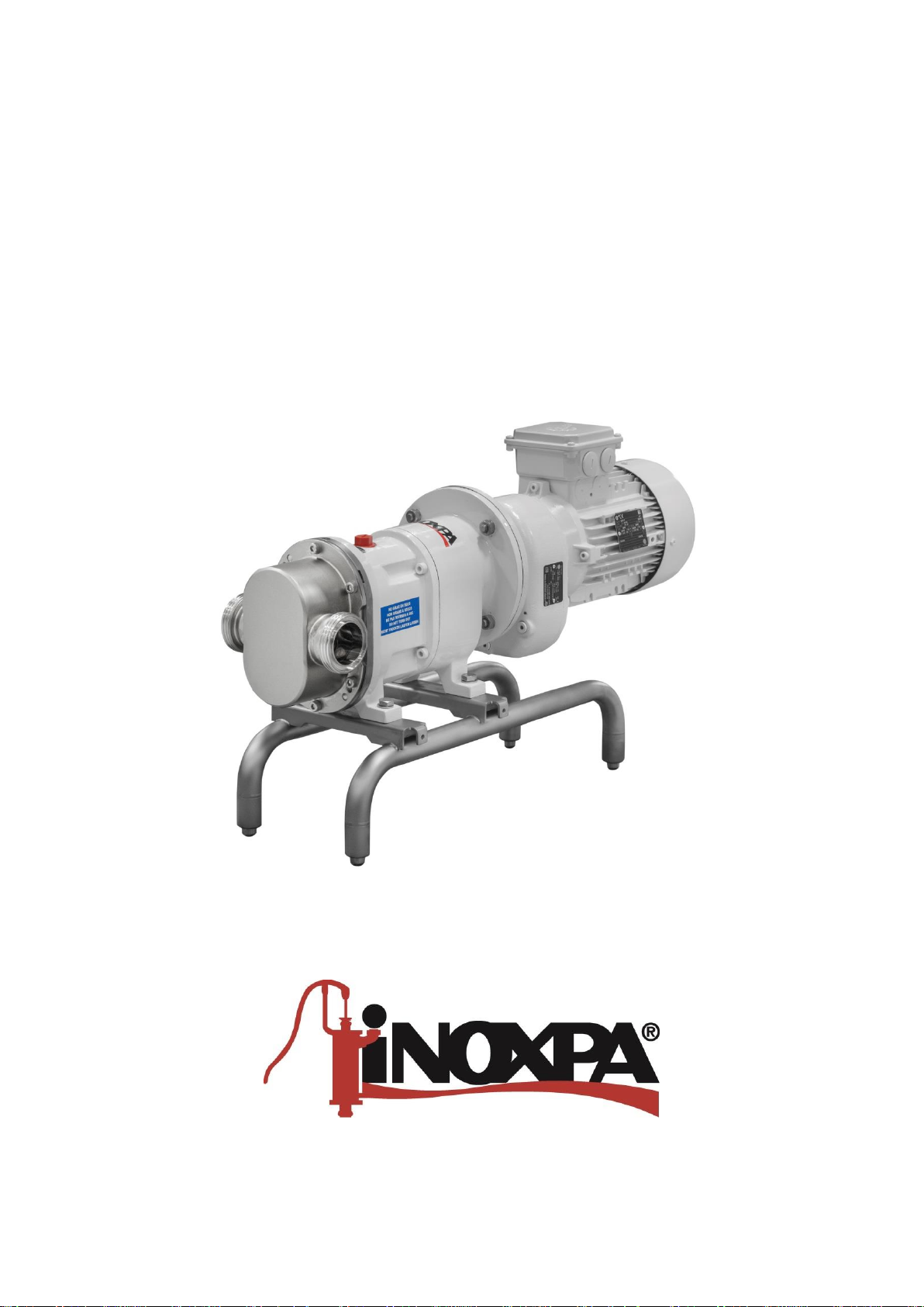
INSTALLATION, SERVICE AND MAINTENANCE INSTRUCTIONS
LOBE PUMP
TLS
Original Manual
01.520.30.07EN
(0) 2019/04
Page 2

01.520.30.06EN
01.520.30.06EN
EC Declaration of Conformity
We,
INOXPA, S.A.U.
Telers, 60
17820 – Banyoles (Girona)
hereby declare under our sole responsibility that the machine
CLOSE-COUPLED ROTARY LOBE PUMP
Designation
TLS
Type
TLS 1-25, TLS 1-40, TLS 2-40, TLS 2-50, TLS 3-50, TLS 3-80
From serial number IXXXXXX to IXXXXXX
(1)
/ XXXXXXXXXIIN to XXXXXXXXXIIN
(1)
Fulfills all the relevant provisions of the following directive:
Machinery Directive 2006/42/EC
Applicable harmonized standards:
EN ISO 12100:2010
EN 809:1998+A1:2009/AC:2010
EN 60204-1:2006+A1:2009
In compliance with regulation (EC) nº 1935/2004 on Materials and articles intended to come
into contact with food
The technical file has been prepared by the signer of this document in INOXPA
David Reyero Brunet
Technical Officer Manager
Banyoles, April 30, 2019
(0) 2019/04
(1)
The serial number may be preceded by a slash and by one or two alphanumeric characters
Page 3

1. Table of Contents
1. Table of Contents
2. Generalities
2.1. Instructions manual .................................................................................................................................... 4
2.2. Compliance with the instructions ................................................................................................................ 4
2.3. Warranty ..................................................................................................................................................... 4
3. Safety
3.1. Warningy symbols ...................................................................................................................................... 5
3.2. General safety instructions ......................................................................................................................... 5
4. General Information
4.1. Description .................................................................................................................................................. 7
4.2. Principle of operation .................................................................................................................................. 7
4.3. Application .................................................................................................................................................. 7
5. Installation
5.1. Reception of the pump ............................................................................................................................... 9
5.2. Identification of the pump ........................................................................................................................... 9
5.3. Transport and storage .............................................................................................................................. 10
5.4. Location .................................................................................................................................................... 10
5.5. Pipes ......................................................................................................................................................... 11
5.6. Electrical installation ................................................................................................................................. 11
6. Start-up
6.1. Checks before starting the pump ............................................................................................................. 12
6.2. Checks when starting the pump ............................................................................................................... 12
6.3. By-pass de presión ................................................................................................................................... 12
7. Troubleshooting
8. Maintenance
8.1. General considerations ............................................................................................................................ 15
8.2. Check the mechanical seal ...................................................................................................................... 15
8.3. Oiling ........................................................................................................................................................ 15
8.4. Storage ..................................................................................................................................................... 15
8.5. Cleaning ................................................................................................................................................... 16
8.6. Disassembly and assembly of the pump .................................................................................................. 17
9. Technical Specifications
9.1. Materials ................................................................................................................................................... 23
9.2. Mechanical seal ........................................................................................................................................ 23
9.3. Size of particle .......................................................................................................................................... 24
9.4. Tightening torques .................................................................................................................................... 24
9.5. Weights ..................................................................................................................................................... 24
9.7. Dimensions ............................................................................................................................................... 25
9.8. Exploded drawing ..................................................................................................................................... 26
9.9. Parts list .................................................................................................................................................... 27
9.10. TLS Shroud .............................................................................................................................................. 28
9.11. LIP Seal .................................................................................................................................................... 29
Page 4
Generalities
Please do not hesitate to contact us in case of doubts or if further explanations are required regarding
specific data (adjustments, assembly, disassembly, etc.).
2. Generalities
2.1. INSTRUCTIONS MANUAL
This manual contains information about the reception, installation, operation, assembly, disassembly and
maintenance of the lobe pump TLS.
Carefully read the instruction prior to starting the agitator, familiarize yourself with the installation, operation and
correct use of the agitator and strictly follow the instructions. These instructions should be kept in a safe location
near the installation area.
The information published in the instruction manual is based on updated data.
INOXPA reserves the right to modify this instruction manual without prior notice.
2.2. COMPLIANCE WITH THE INSTRUCTIONS
Not following the instructions may impose a risk for the operators, the environment and the machine, and may
result in the loss of the right to claim damages.
This non-compliance may result in the following risks:
Failure of important machine/plant functions.
Failure of specific maintenance and repair procedures.
Possible electrical, mechanical and chemical hazards.
Risk to the environment due to the type of substances released.
2.3. WARRANTY
Any warranty will be void immediately and lawfully and, additionally, INOXPA will be compensated for any civil
liability claims submitted by third parties, in the following cases:
The service and maintenance work have not been carried out in accordance with the service instructions,
the repairs have not been carried out by our personnel or have been carried out without our written
authorisation.
Modifications have been carried out on our material or equipment without written authorisation.
The parts or lubricants used are not original INOXPA parts and products.
The material or equipment has been improperly used, has been used negligently, or has not been used
according to the instructions and their intended.
The General Conditions of Delivery already in your possession are also applicable.
The machine may not undergo any modification without prior approval from the manufacturer.
For your safety, only use original spare parts and accessories.
The usage of other parts will relieve the manufacturer of any liability.
Changing the service conditions can only be carried out with prior written authorization from
INOXPA.
4 INOXPA S.A.U. · 01.520.30.07EN · (0) 2019/04
Page 5
Safety
ATTENTION
3. Safety
3.1. WARNING SYMBOLS
Safety hazard for people in general and/or for equipment
Electric hazard
Important instruction to prevent damage to the equipment and its functions
3.2. GENERAL SAFETY INSTRUCTIONS
Read the instruction manual carefully before installing and starting the agitator. Contact INOXPA in
case of doubt.
3.2.1. During the installation
The Technical Specifications of chapter 9 should always be observed.
Never start the pump before connecting it to the lines.
Check for proper specifications of the motor, especially if its working conditions create an explosion
hazard.
All electric work should be carried out by specialised personnel.
3.2.2. During operation
The Technical Specifications of chapter 9 should always be observed. Under no circumstances can
the specified limit values be exceeded.
NEVER touch the pump or the pipework during operation if the pump is being used for transferring
hot liquid of during cleaning.
The pump has rotating parts. Do not place hands or fingers in the agitator while it is operating. This
may cause serious injuries.
NEVER operate with the suction and discharge valves closed.
NEVER spray water directly on the electrical motor. The standard motor protection is IP-55:
protection against dust and water spray.
3.2.3. During maintenance
The Technical Specifications of chapter 9 shall always be observed.
NEVER disassemble the pump until the pipes have been emptied. Remember that liquid will
remain inside the pump’s body (if does not have a purge). Bear in mind that the pumped liquid may
be hazardous or extremely hot. Consult the regulations in effect in each country for these cases.
Do not leave loose parts on the floor.
INOXPA S.A.U. · 01.520.30.07EN · (0) 2019/04 5
Page 6

Safety
ALWAYS disconnect the electrical power to the pump prior to carrying out any maintenance.
Remove the fuses and disconnect the cables from the motor’s terminals.
All electrical work must be carried out by authorised personnel.
6 INOXPA S.A.U. · 01.520.30.07EN · (0) 2019/04
Page 7
General Information
01.520.32.0002
4. General Information
4.1. DESCRIPTION
The TLS lobes pumps by INOXPA are part of our wide range of positive displacement rotary pumps for viscous
liquids.
The following models exist in the lobe pump range:
The TLS normal flow rate pump suitable for pressures of up to 12 bar.
The TLS with wider lobes, delivers a higher flow rate, and is suitable for pressure of up to 7 bar.
The TLS model has been specially developed to respond to all hygienic requirements in the food industry.
As regards higiene, reliability and sturdiness, the complete range of lobes pumps satisfies all requirements set
by the aforesaid industry.
The rotary lobe pumps are positive displacement pumps. Owing to the contact between the internal parts, the
pressure variations, etc. they make a louder noise than centrifugal pumps. This noise must be taken into
consideration when installing these pumps.
4.2. PRINCIPLE OF OPERATION
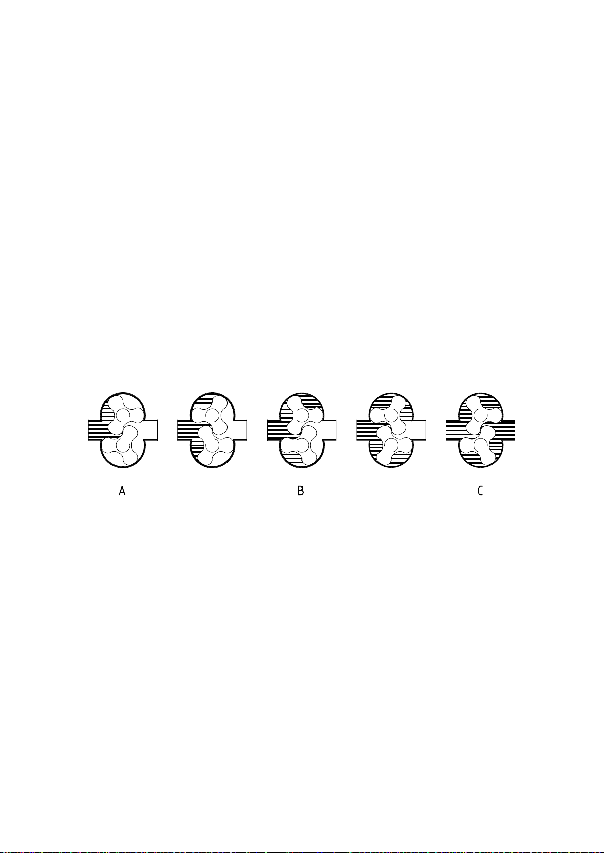
The lob pump is a positive displacement rotary pump. The top lobe is driven by the driving shaft. The lower lobe
is located on the driven shaft, and is driven via a helical gear. Both lobes rotate in synchronism without one
touching the other. When the pump is running they displace a set volume of liquid. The following figures show
how a lobe pump operates.
A: when the lobes rotate, the space on the suction side increases because one lobe moves away from the
other, thus causing a partial vacuum that draws the liquid into the pumping chamber.
B: each lobe void is filled consecutively as the shafts rotate and the liquid is displaced towards the discharge
side. The small clearances between the lobes and between the lobes and the walls of the pump body duly
cause the spaces to be rather well closed.
C: the pump casing is completely full and the liquid leaks through the meshing of the lobes, knocking against the
space walls so as to thus complete the pumping action
4.3. APPLICATION
The main advantage of the INOXPA TLS lobe pump is its capacity to pump a great variety of viscous liquids,
from 1 mPa.s up to 100.000 mPa.s.
Furthermore, it is capable of pumping liquid products that require very careful handling and liquids that contain
soft solids thus causing only a minimum degradation of same.
The intended use of the pump is defined by its characteristic curve and operating limits provided in the chapter
9. Technical Specifications.
INOXPA S.A.U. · 01.520.30.07EN · (0) 2019/04 7
Page 8
General Information
ATTENTION
Misuse of the pump or its use beyond the operating limits may be dangerous or cause permanent
damage the equipment
8 INOXPA S.A.U. · 01.520.30.07EN · (0) 2019/04
Page 9
Installation
1
Serial number
01.520.32.0003
01.520.32.0004
5. Installation
5.1. RECEPTION OF THE PUMP
INOXPA will not be liable for any deterioration of the material due to transport or unpacking.
Visually check that the packaging has not been damaged.
The following documentation is included with the pump:
shipping documents,
instructions and servicing manual for the pump,
instructions and servicing manual for the motor1.
Unpack the pump and check the following:
The suction and discharge connections on the pump, removing any remaining packaging material.
Check that the pump and motor have not suffered any damage.
If not in good material condition and/or if not all the parts are included, the shipping carrier should submit
a report as soon as possible.
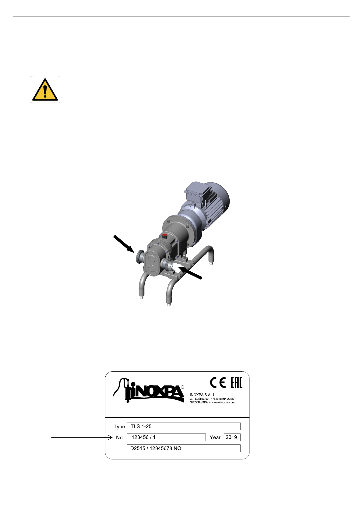
5.2. IDENTIFICATION OF THE PUMP
Each pump has a nameplate with the basic data required to identify the model.
If the pump and check the following INOXPA
INOXPA S.A.U. · 01.520.30.07EN · (0) 2019/04 9
Page 10
Installation
ATTENTION
ATTENTION
ATTENTION
01.520.32.0005
5.3. TRANSPORT AND STORAGE
The TLS pumps are often too heavy to be stored manually.
Use an appropriate mode of transport.
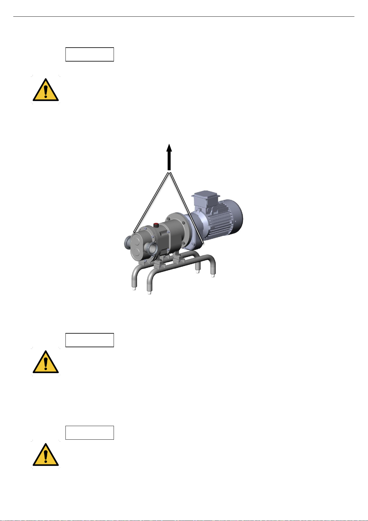
Use the points which are indicated in the drawing for lifting the pump.
Only authorized personnel should transport the pump.
Do not work or walk under heavy loads.
Lift the pump as indicated below:
Always use two support points placed as far apart as possible.
Secure the support so that they will not move.
See chapter 9. Technical Specifications to consult dimensions and weights.
During the transport, disassembly or assembly of the pump, there is a risk of loss of stability and
that the pump could fall down and cause damages to the operators. Make sure that the pump is
properly supported.
5.4. LOCATION
Leave sufficient space around the pump to provide access to both pump and motor. See chapter 9.
Technical Specifications to consult dimensions and weight.
Place the pump on a flat and level surface.
Install the pump so that it can be properly ventilated.
If the pump is installed outdoors, it must be sheltered under a roof. Its location must allow for easy
access during any inspection or maintenance tasks.
10 INOXPA S.A.U. · 01.520.30.07EN · (0) 2019/04
Page 11
Installation
ATTENTION
01.520.32.0006
5.5. PIPES
As a general rule, install the suction and discharge lines in straight sections, with the minimum possible
number of elbows and fittings in order to reduce any pressure losses that may be caused by friction.
Make sure that the pump’s ports are properly aligned with the pipework and have a diameter similar to
that of the pump connections.
Place the pump as close as possible to the suction tank and whenever possible below the liquid level, or
even below the tank level in order to achieve the largest possible static head for suction.
Install support brackets for the lines as close as possible to the pump's suction and discharge ports.
5.5.1. Shut-off valves
The pump may be isolated for maintenance. To accomplish this, shut-off valves must be installed and
connected to the pump’s suction and discharge connections.
This valves must ALWAYS be open during operation of the pump.
5.6. ELECTRICAL INSTALLATION
Only qualified personnel can connect the electric motors
Take the necessary measures to prevent damage to cables and connections.
Electrical equipment, terminals and components of the control systems may still carry current when
they are disconnected. Contacting them may impose a hazard to operators or cause irreparable
material damage
Prior to handling the pump, make sure that the electrical panel is disconnected.
Connect the motor in accordance with the instructions supplied by the motor manufacturer and in
accordance with the current legislation and according to the standard EN 60204-1.
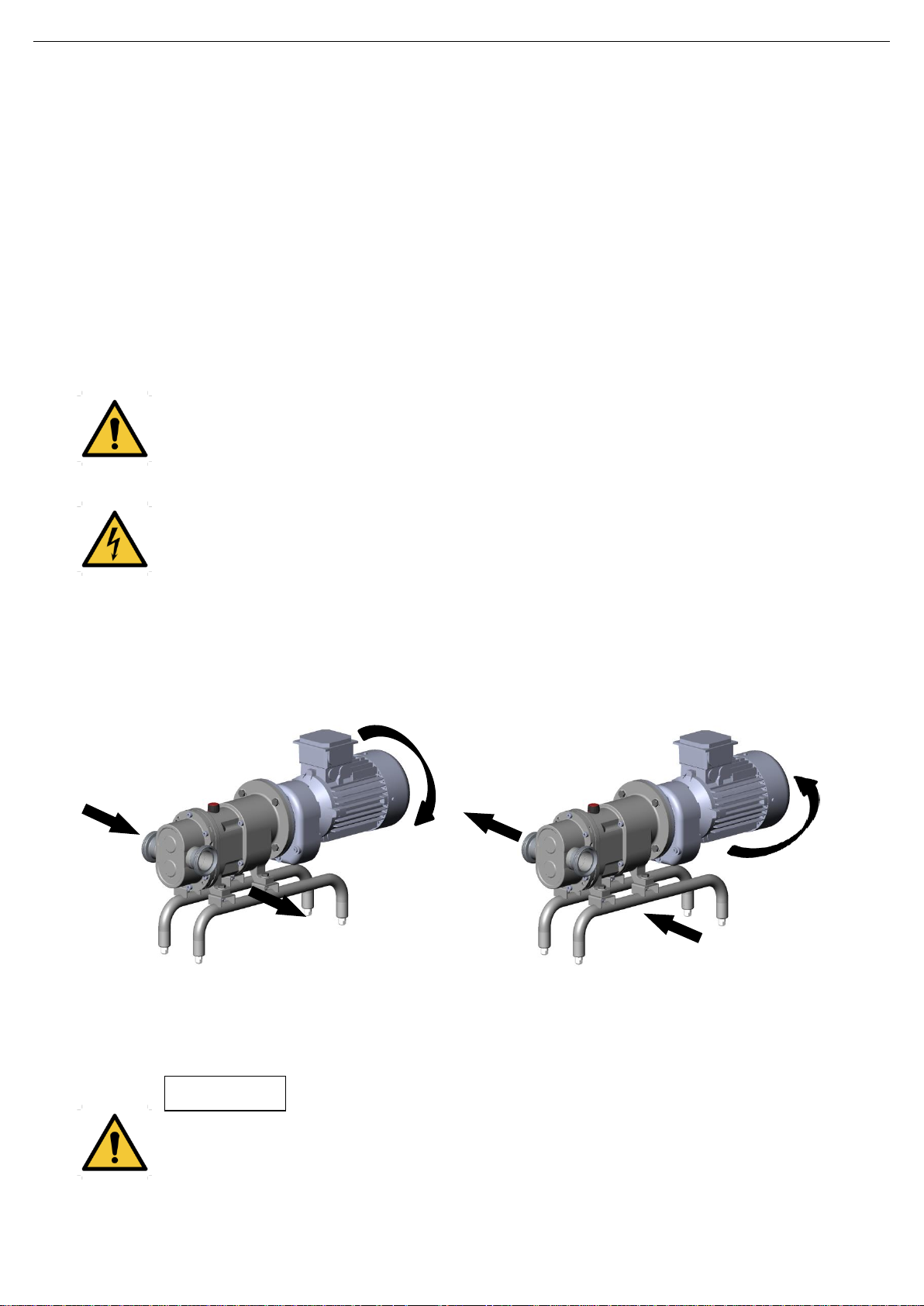
Check the direction of rotation that determines which is the suction and discharge direction.
If the direction of rotation is reversed, the direction of the flow changes the direction also.
Start and stop the pump motor momentarily. Make sure that the pump rotates in the correctly direction of
rotation.
ALWAYS check the direction of rotation of the motor with liquid inside the pump.
INOXPA S.A.U. · 01.520.30.07EN · (0) 2019/04 11
Page 12
Start-up
ATTENTION
ATTENTION
6. Start-up
Prior to starting the pump, carefully read the instructions in chapter 5. Installation.
Carefully read chapter 9. Technical Specifications. INOXPA will not be liable for improper use of
the equipment.
NEVER touch the pump or the lines if hot liquids are being pumped.
6.1. CHECKS BEFORE STARTING THE PUMP
Completely open the shut-off valves on the suction and discharge lines.
If liquid does not flow towards the pump, fill it with the liquid to be pumped.
Remove the secure transport of gear oil plug.
Check oil level of the pump. Add correct grade of oil as necessary to maintain level in centre of oil sight
glass. In the case of first start-up, pumps are shipped with oil in the gearbox.
The pump must never turn dry.
Check that the direction of rotation of the motor is correct and adequate for the application.
6.2. CHECKS WHEN STARTING THE PUMP
Check that the pump is not making any strange noises.
Check if the absolute inlet pressure is sufficient to prevent cavitation in the pump. Check the curve to
obtain the minimum required pressure above the vapour pressure (NPSHr).
Control the discharge pressure.
Check for leaks in the sealing areas.
A shut-off valve shall not be used to regulate the flow in the suction line. All shut-off valves must be
fully open during operation.
Control the motor consumption to prevent an electrical overload.
Reduce flow and motor power consumption by reducing motor speed.
6.3. BY-PASS DE PRESIÓN
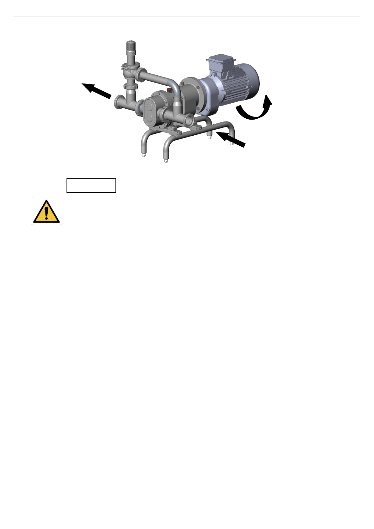
When pump has a pressure by-pass, pump only can rotate in one direction. To reverse the direction of the
pump’s rotation, the assembly of the by-pass must also be reversed.
The valve's opening pressure depends on the fluid to be pumped, its viscosity, its rpm, etc. and so before
starting-up the pump, the operator ought to adjust the pressure relief valve's opening pressure.
12 INOXPA S.A.U. · 01.520.30.07EN · (0) 2019/04
Page 13
Start-up
ATTENTION
01.520.32.0007
When an overflow valve or a pressure bypass is installed, the valve is adjusted to the maximum
working pressure of the pump. The end user must adjust the valve to the correct pressure.
When an overflow valve or a pressure bypass does not operate properly, the pump must
immediately be removed from service for repair.
INOXPA S.A.U. · 01.520.30.07EN · (0) 2019/04 13
Page 14
Troubleshooting
Motor overload
The pump flow or pressure is insufficient.
There is no pressure on the discharge side.
Irregular discharge flow rate / pressure.
Noise and vibrations.
The pump gets clogged.
Pump overheated.
Abnormal wear.
Leak through the mechanical seal.
CAUSAS PROBABLES
SOLUCIONES
• •
Wrong direction of rotation.
Reverse the direction of rotation.
• • • •
Insufficient NPSH
Raise the suction tank.
Lower the pump.
Reduce the vapour pressure.
Widen the diameter of the suction pipe.
Shorten and simplify the suction line.
•
Pump not purged
Purge or fill.
• • • •
Cavitation.
Increase the suction pressure.
• • • •
The pump sucks in air.
Check the suction line and all of its
connections.
• • •
Suction pipe obstructed
Check the suction line and the filters, if
available.
• • • •
Wrong setting of safety valve
Check the safety valve’s setting
• •
Discharge pressure too high
If necessary, reduce the pressure losses,
for example, by increasing the pipe
diameter.
• • • •
Pump speed too high
Reduce the speed of the pump.
• • • • • •
Viscosity of the liquid too high.
Reduce the speed of the pump.
Reduce the viscosity, for example, by
heating the liquid.
• • • • •
Liquid temperature is too high
Decrease the temperature by cooling the
liquid.
•
Mechanical seal worn or damaged.
Replace the seal.
• •
The lobes are worn
Replace the lobes
•
Inadequate O-rings for the liquid.
Install the correct O-rings after consulting
the supplier.
• • • • •
Worn bearings
Replace the bearings, check the pump
• • •
Worn gears
Replace and readjust the gears
• • • •
Tension in the lines.
Connect the pipes to the pump without
tension.
• • • •
Foreign matter in the liquid.
Install a filter in the suction pipe.
•
Mechanical seal spring tension is too low.
Adjust as indicated in this manual.
• • • •
Insufficient lubricating oil level
Fill up with oil
• • • •
Unsuitable lubricating oil
Use an appropriate oil
• • • •
The lobes rub
Reduce the temperature
Reduce the discharge pressure
Adjust the clearance
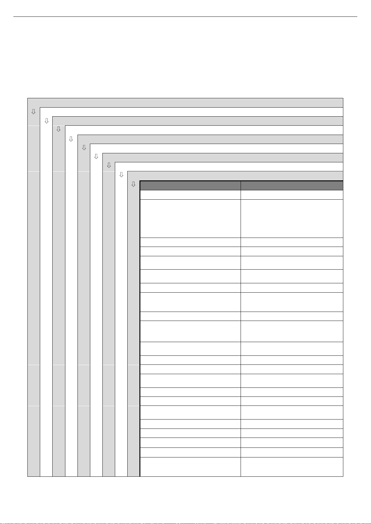
7. Troubleshooting
The attached table lists solutions to problems that may arise while operating the pump. It is assumed that the
pump has been properly installed and that is has been selected correctly for the specific application.
Contact INOXPA if technical assistance is required.
14 INOXPA S.A.U. · 01.520.30.07EN · (0) 2019/04
Page 15
Maintenance
Pump size
Quantity of oil in
the gear case (l)
TLS 1
0,7
TLS 2
1
TLS 3
2
ATTENTION
8. Maintenance
8.1. GENERAL CONSIDERATIONS
This pump, just like any other machine, requires maintenance. The instructions contained in this manual cover
the identification and replacement of spare parts. The instructions are aimed at maintenance personnel and
those responsible for the supply of spare parts.
Carefully read chapter 9. Technical Specifications.
Maintenance work can only be carried out by qualified personnel that are trained and equipped
with the necessary resources to carrying out this work.
All parts or materials that are replaced must be properly disposed of/recycled in accordance with
the current directives applicable in each area.
ALWAYS disconnect the pump before beginning any maintenance work.
8.2. CHECK THE MECHANICAL SEAL
Periodically check that there are no leaks around the shaft. If leakage is detected through the mechanical seal,
replace it following the instructions in the chapter 8.6. Disassembly and assembly of the pump.
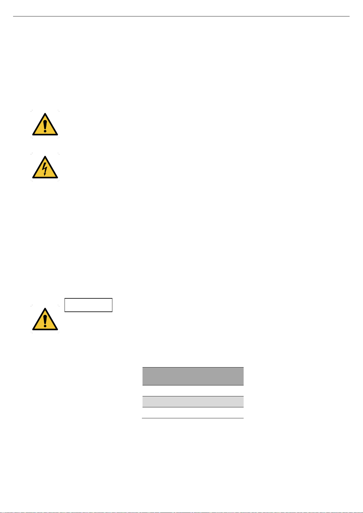
8.3. OILING
The bearings are oiled by immersion in an oil bath.
The pumps are supplied with oil.
Regularly check the oil level, for example, weekly or every 150 operating hours.
The first oil change must be carried out after 150 hours of operation.
Afterwards, it can be changed every 2500 operating hours or at least once a year when operating under
normal conditions.
When change the oil: the oil sump must be filled up to the level in the middle of the peephole.
Do not pour too much oil into the sump.
Leave the pump switched off for a while and then re-check the oil level. If is necessary, add a little oil.
Oils for environment temperatures of 5 to 50ºC: SAE 90 or ISO VG 220
8.4. STORAGE
Before storing the pump it should be completely drained. Prevent as far as possible exposing the parts to
excessively humid environments.
INOXPA S.A.U. · 01.520.30.07EN · (0) 2019/04 15
Page 16
Maintenance
Cleaning solutions for CIP processes. Only use clear water (chlorine-free) to mix
with the cleaning agents:
a) Alkaline solution: 1% by weight of caustic soda (NaOH) a 70ºC (150ºF)
1 Kg NaOH + 100 l H2O = cleaning solution
o
2,2 l NaOH al 33% + 100 l H2O = cleaning solution
b) Acid solution: 0,5% by weight of nitric acid (HNO3) a 70ºC (150ºF)
0,7 litros HNO3 al 53% + 100 l H2O = cleaning solution
Maximum conditions during the SIP process with steam or overheated water:
a) Max. temperature: 140°C / 284°F
b) Max. time: 30 min
c) Cooling: sterile air or inert gas
d) Materials: EPDM/PTFE (recommended)
FPM/NBR (not recommended)
ATTENTION
8.5. CLEANING
The use of aggressive cleaning products such as caustic soda and nitric acid may burn the skin..
Use rubber gloves during the cleaning process.
Always use protective goggles.
8.5.1. CIP (clean-in-place) cleaning
If the pump is installed in a system with a CIP process, its removal will not be required.
If an automatic cleaning process is not available, disassemble the pump as indicated in the chapter 8.6.
Disassembly and assembly of the pump.
Check the concentration of the cleaning solutions; incorrect concentrations may lead to
deterioration of the pump seals.
To remove any traces of cleaning products, ALWAYS perform a final rinse with clean water at the end of the
cleaning process.
8.5.2. SIP (sterilization-in-place) cleaning
Sterilization with steam is applied to all equipment including the pump.
Do NOT use the equipment during the steam sterilization process.
The parts/materials will not be damaged if the indications specified in this manual are observed.
Make sure that no cold liquid enters the system until the temperature of the pump is lower than
60°C (140°F).
The pump generates an important pressure loss through the sterilization process. We recommend
the use of a branch circuit with a discharge valve to ensure that steam / superheated water
sterilizes the integrity of the circuit.
16 INOXPA S.A.U. · 01.520.30.07EN · (0) 2019/04
Page 17
Maintenance
ATTENTION
01.520.32.0009
8.6. DISASSEMBLY AND ASSEMBLY OF THE PUMP
The assembly and disassembly of the pumps should be done by qualified personnel. Make sure that the
personnel read carefully this instruction manual and, in particular, those instructions which refer to the work they
will perform.
Incorrect assembly or disassembly may cause damage in the pump’s operation and lead to high
repair costs and a long period of down time.
INOXPA is not responsible for accidents or damages cause by a failure to comply with the
instructions in this manual.
Preparation
Provide for a clean working environment so some parts, including the mechanical seal, require very careful
handling and others have close tolerances.
Check that the parts which are used are not damaged during transport. When doing this, you need to inspect
the adjustment edge, the butted faces, the tight fit, burrs, etc.
After each disassembly, carefully clean the parts and check for any damage. Replace all damaged parts.
Tools
Use the proper tools for assembly and disassembly operations. Use them correctly.
Cleaning
Before disassembling the pump, clean it on the outside on the inside.
NEVER clean the pump by hand when it is running.
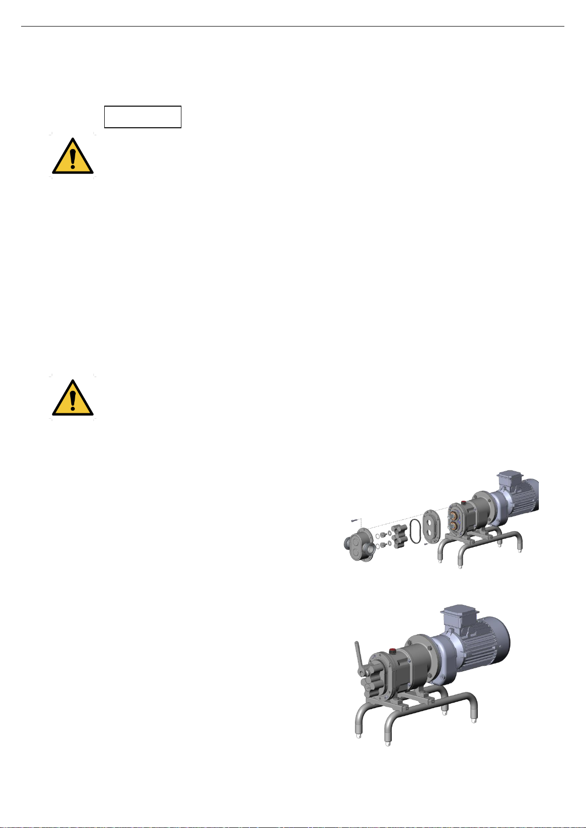
8.6.1. Pump casing, lobes and seal cover
Disassembly
Remove the Allen screws (51) and disassemble the
pump casing (01).
Remove the lobe screws (25) using a wrench that could
deliver by Inoxpa. These screws are threaded to the
right. Wooden or nylon blocks can be placed between
the lobes to stop them from rotation (blocks position: one
to the left in front of the top lobe screw and the other to
the right in front of the lower lobe screw).
Check that the O-ring (80) is still in good condition.
Loosen the Allen screws (51E) that attach the seal cover
(09) to the support. There are two notches to loosen the
pump cover, for example, using a screwdriver. Two pins
(56) are used to centre the cover.
Press the notches so that the both lobes (02) and the
pump cover are loosened. If necessary, use a suitable
tool.
When the Allen screws (51E) have been removed, the
lobes and the pump cover can also be taken apart. The
rotating part of the mechanical seal (08) remains
situated in the shaft sleeve (13).
INOXPA S.A.U. · 01.520.30.07EN · (0) 2019/04 17
Page 18
Maintenance
01.520.32.0010
01.520.32.0011
Assembly
Fit the seal cover (09) in the support (06). During the assembly of the seal cover observe the
position of the centering pins (56).
Tighten the Allen screws (51E).
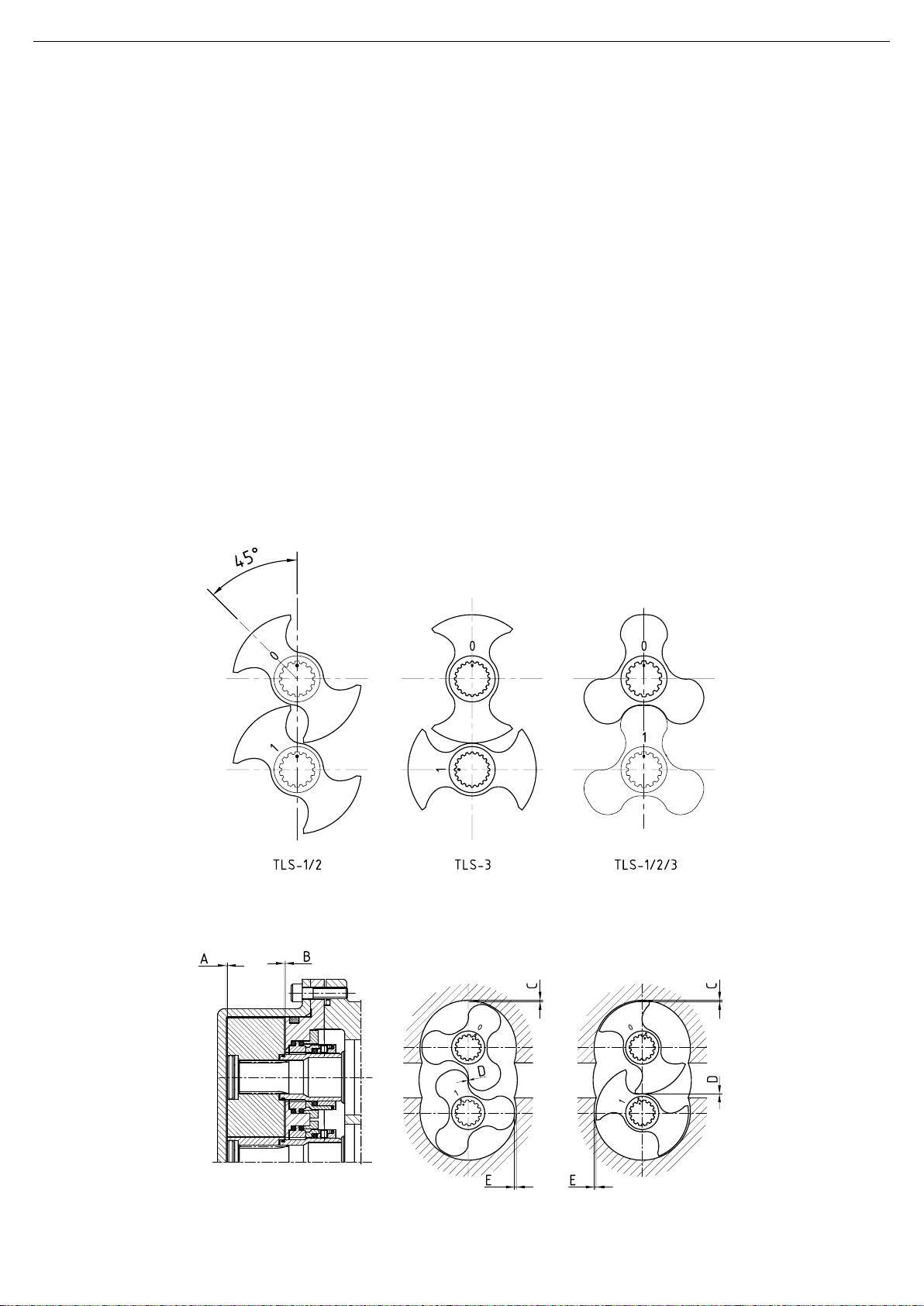
Slide the lobes onto the shafts as far as the shaft sleeve. Observe the markings (0 - 1 and ) from
the figure shown below.
Rotate the driving shaft a few times and make sure that the lobes do not touch each other. If
necessary, refer to the section describing how to adjust the lobes.
Check that the O-rings (80) of the lobe screws (25) are still in a good condition and that they are
correctly positioned in the groove.
Fit the lobes with the screws (25) and the washers (35). Tighten the screws with a wrench as
shown in previous figure. A wooden or nylon block can be placed between the lobes to avoid that
they rotate simultaneously.
Check that the front parts of both lobes are aligned.
Make sure that the clearance both behind and between the lobes is similar to that shown in the
page.
Check to see that the O-ring (80A), located in the seal cover (09), is still in good condition.
Place the O-ring (80A) on the seal cover (09). Make sure that the O-ring is not place on the inverted
position and abundantly lubricated the seal surface.
Once the pump casing is assembled, the Allen screws (51) must be tightened (crosswise).
8.6.1.1. Markings and lobes positions
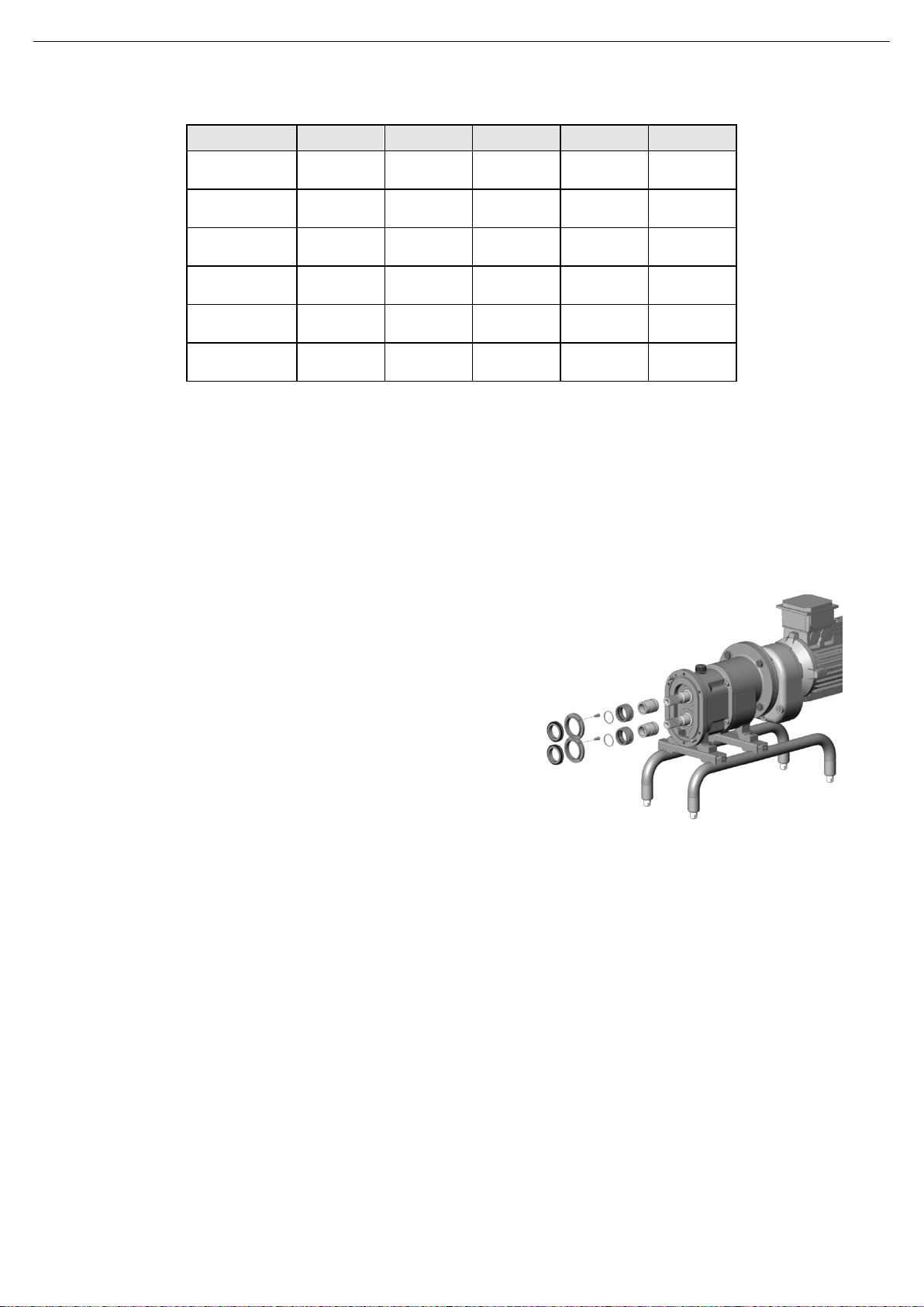
8.6.1.2. TLS pump clearances and tolerances
18 INOXPA S.A.U. · 01.520.30.07EN · (0) 2019/04
Page 19
Maintenance
(mm)
A B C D E
TLS 1-25
0,15
±0,05
0,1
±0,05
0,15
±0,05
0,15
±0,05
0,35
±0,05
TLS 1-40
0,15
±0,05
0,1
±0,05
0,2
±0,05
0,15
±0,05
0,4
±0,05
TLS 2-40
0,2
±0,05
0,15
±0,05
0,15
±0,05
0,15
±0,05
0,35
±0,05
TLS 2-50
0,2
±0,05
0,15
±0,05
0,2
±0,05
0,15
±0,05
0,4
±0,05
TLS 3-50
0,25
±0,05
0,2
±0,05
0,2
±0,05
0,2
±0,05
0,4
±0,1
TLS 3-80
0,3
±0,05
0,2
±0,05
0,3
±0,05
0,2
±0,05
0,5
±0,1
01.520.32.0012
A = axial clearance between the lobe and the pump cover
B = radial clearance between the lobe and back side pump casing
C = radial clearance between lobe and the pump casing top and bottom
D = radial clearance between lobes
E = radial clearance between lobe and pump casing at inlet and outlet
Dimensions in mm
8.6.2. Mechanical seal, shaft sleeve and seal covers
Disassembly
One time the seal cover (09) has been disassembled, as
indicated in the foregoing section, take out the back seal
cover (09A) - the stationary part of the mechanical seal
(08A) comes out of the pump cover -. Measures have
been taken to avoid that this face could rotate
simultaneously with the shaft.
Loosen the screws (50B -support 1-, 51F -support 2 and
3-) that attach the back seal cover (09A) to the seal
cover (09). Take the stationary part of the mechanical
seal (08A) out.
Check that the rubbing face and the O-rings are in good
condition.
The rotating part of the seal (08) remains in the shaft
sleeve (13).
Dismantle the shaft sleeve (13). If this sleeve is stuck to
the shaft, a screwdriver, for example, can be introduced
in between the sleeve and the shaft.
Assembly
Check that the sealing surface of the rotary face, the O-ring and the shaft sleeve are still in good
condition.
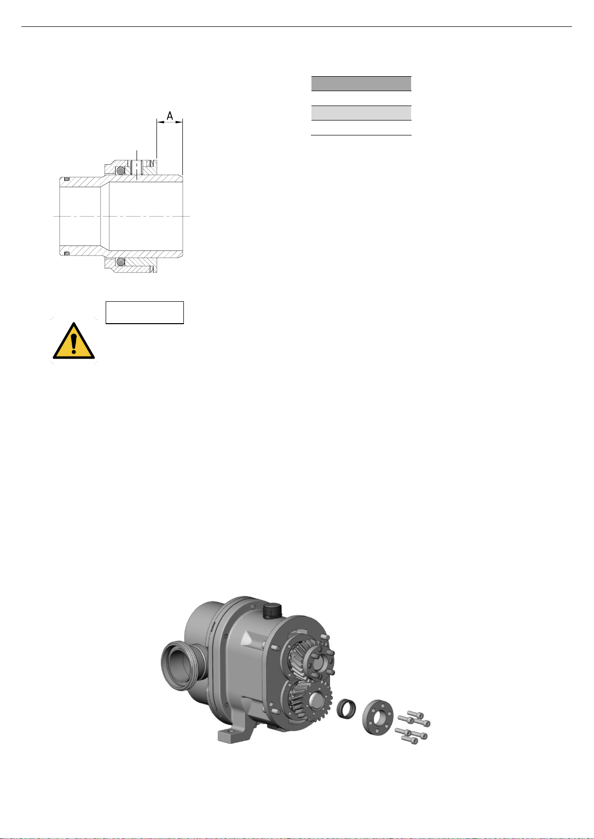
The rotating part of the mechanical seal (08) has to be fitted first on to the shaft sleeve. Use soapy
water to best assembly.
If the adjustment ring in the rotating part of the mechanical seal is dismantled, it must be readjusted
when the seal and sleeve are assembled, and placed at the end of the sleeve and positioned between
the shaft's two dragging pivots; see the next figure and table. Then, the rotating part of the mechanical
seal (08) with the O-ring and the spring can also be mounted.
Slide the sleeves on to the shafts.
Fit the O-rings (80D) onto the shaft sleeves.
Position the stationary part (08A) of the mechanical seal in its location in the seal cover.
Fit the back seal cover (09A) in the seal cover (09) and tighten the screws (50B) on the support 1 or the
screws (51F) on the supports 2 and 3.
INOXPA S.A.U. · 01.520.30.07EN · (0) 2019/04 19
Page 20
Maintenance
Model
A
TLS 1
8
TLS 2
4
TLS 3
4,8
ATTENTION
01.520.32.0013
01.520.32.0014
When installing the new seal, use soapy water when fitting the different parts and gaskets to allow
them to slide better; apply to the stationary as well as the rotating parts.
8.6.3. Changing the lip seal
Disassembly the seal cover (09). See chapter 8.6.1. Pump casing, lobes and seal cover.
Disassembly the back seal cover (09A) loosening the screws (50B on the support 1 or 51B on the
support 2 and 3) that they fix the seal cover with the pump cover.
Now the lip seal is visible in the seal cover
Check if the lip seal element (08C) is in good condition. If necessary, the lip seal element can be
replaced after the lip seal cover (09B) has been removed
Check if the shaft sleeve (13A) is in good condition. To disassembly the shaft sleeve see the mechanical
seal and shaft sleeve instructions in chapter 8.6.2. Mechanical seal, shaft sleeve and seal covers.
Slightly grease the shaft sleeves local to the lip seal element before assembly of the lip seal cover.
8.6.4. Adjusting the lobes
To adjust the lobes, the lantern unit and the geared motor must be removed from the support. For this purpose,
the housing, the lobes, the pump cover and the seals must be disassembled first, as indicated in the relevant
section.
Empty the oil from the support, remove the oil plug (85) and the bleed-emptying plug (87).
20 INOXPA S.A.U. · 01.520.30.07EN · (0) 2019/04
Page 21
Maintenance
01.520.32.0015
01.520.32.0016
Remove the allen screws (51B) which have been used to attach the lantern (04) in the support (06).
These screws are centred respectively by means of two centring pins (56A).
Gently tap the lantern with a plastic hammer. When the lantern is slightly loosened from the support,
make sure the seal (18B) does not stick to both sides. If necessary, loosen the seal.
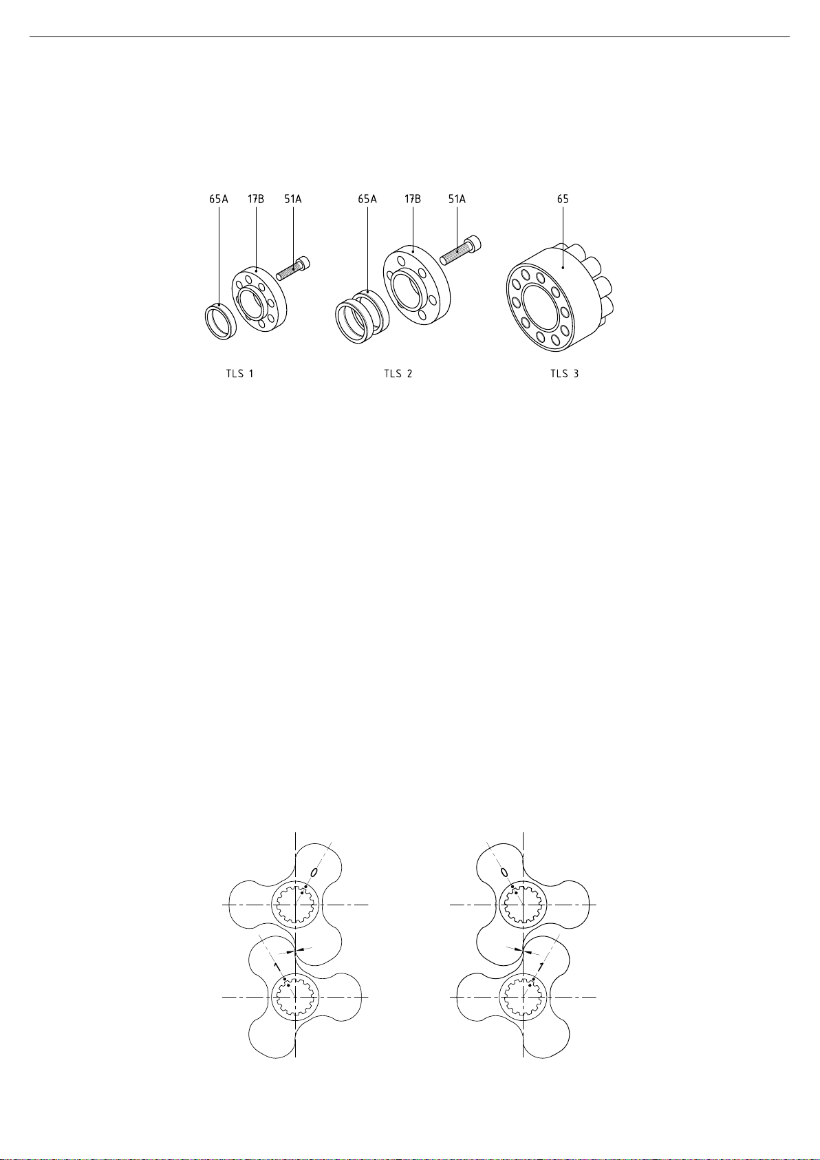
Loosen the take up screws of the adjustable fastening mechanism for the driven gear (19A), see the
next figure. In theory, the take up unit is self-releasing. It is now possible to rotate the driving shaft,
whilst the driven shaft can be held stationary.
TLS 1 y TLS 2: the adjustable fastening system is made up of three parts: Allen screws (51A), conical
tightening rings (65A) and dragging bushing (17B).
TLS 3: the adjustable fastening system consists in one single part (65).
Slide the lobes onto the shafts as shown in the figure from chapter 8.6.1.1. Marking and lobes positions.
Press the lobes against the shaft sleeve.
Now rotate the lobes to the position indicated from the next figure. Then, rotate a little the both lobes one
reference the other, until the clearance (throw) has been to indicate in table from chapter 8.6.1.2. Pump
clearances and tolerances.
Tighten a few of the adjustable fastening mechanism take up screws by hand.
Now rotate the top lobe 60º to the left; see the next figure. Make sure that the clearance in this position is
the same as that between the lobes in the position shown in the previous figure.
If not so, these clearances should equal rotating a little a lobe and stopping the other.
Tighten the adjustable fastening mechanism take up screws crosswise in 2 or 3 passes and with the
established tightening torque.
When tightening the adjustable fastening mechanism screws, take care to avoid that the gears rotate
with regard to each other. This can be prevented by placing a wooden wedge between the gears.
Re-check the mutual clearance between the lobes and rotate the driving shaft a few times to make sure
that the lobes do not rub together at all.
Check that the seal (18B) for the lantern has not been damaged and stick it with a little grease in the
correct position against the lantern flange.
Fit the lantern unit and the drive in the support, and on doing so, take care of the centring pins (56A).
Fit the Allen screws (51B).
Fill the oil sump with the recommended oil type; see oiling instructions.
INOXPA S.A.U. · 01.520.30.07EN · (0) 2019/04 21
Page 22
Maintenance
01.520.32.0021
01.520.32.0017
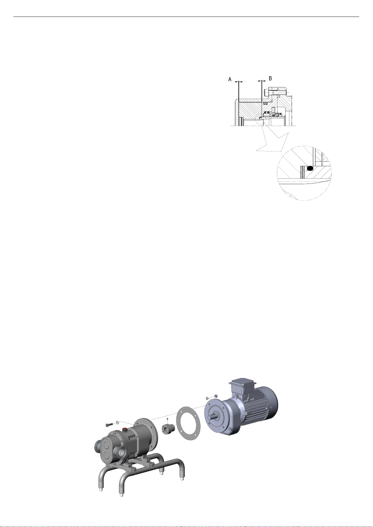
8.6.5. Adjusting lobe pump casing with shims
This is the last adjustment to be done. The pump must
be previously synchronized (adjust the lobes between
them).
In order to have the correct adjustment between the
pump casing (01) and the lobes (02), should we add in
front of the shaft sleeve (13) an adjusting shims to
obtain the correct clearance B (see section 7.4.1.2).
There are 3 different shims available of: 0,1, 0,15 and
0,2 mm.
Assemble the lobes (02) and adjust the screws (25)
according the chapter 8.6.1. Pump casing, lobes and
seal cover.
8.6.6. Changing the lip seals
In order to change the lip seals (88), the pump casing, the lobes and seal cover have to be
disassembled first. See the corresponding section in the manual, and bleed the oil sump.
Lubricate the shafts in the relevant lip seal position.
Fill the oil sump once the lip seals have been changed.
8.6.7. Changing the drive
Empty the oil from the oil sump, remove the oil plug (85) and the bleeding-emptying plug.
Remove the allen screws (51B) which have been used to attach the lantern (04) on the support (06).
These screws are centred respectively by means of two centring pins (56A).
Gently tap the lantern with a plastic hammer. When the lantern is slightly loosened from the support,
make sure the seal (18B) does not stick to both sides. If necessary, loosen the seal.
Remove the screws (51B/51A) that join the lantern to the drive (93).
Gently tap the lantern with a plastic hammer. When the lantern is slightly loosened from the drive, make
sure the seal (18C) does no stick to both sides. If necessary, loosen the seal.
Loosen the studs (55) and dismantle the coupling (41) from the shaft.
Check if the flector (40) is in good condition.
Change the drive.
Once the drive is fitted, fill the oil sump with the oil type recommended in the oiling instructions.
22 INOXPA S.A.U. · 01.520.30.07EN · (0) 2019/04
Page 23
Technical Specifications
Pump siez
DN
Maximum
speed
[rpm]
Maximum
pressure
[bar]
Volume per
revolution
[l/rev]
TLS 1-25
25
1”
950
12
0,10
TLS 1-40
40
1½”
950
7
0,14
TLS 2-40
40
1½”
950
12
0,23
TLS 2-50
50
2”
950
7
0,30
TLS 3-50
50
2”
720
12
0,68
TLS 3-80
80
3”
720
7
0,95
2
3
9. Technical Specifications
Maximum operating pressure 12 bar
Temperature range2 -10ºC a 120ºC (EPDM)
Noise level 61 a 80 dB(A)
Maximum viscosity3 100.000 mPa.s
9.1. MATERIALS
Parts in contact with the product AISI 316L
Other steel parts AISI 304L
Gaskets in contact with the product EPDM (standard)
FPM (other Materials available upon request)
Exterior surface finish Matt
Interior surface finish Polished Ra ≤ 0,8 μm
9.2. MECHANICAL SEAL
Type Single mechanical seal and balanced
Material of rotating part Silicon carbide (SiC) (standard)
Material stationary part Graphite (C) (standard)
Silicon carbide (SiC)
Gasket material EPDM (standard)
FPM / PTFE
Use special protection when the noise level in the operation area exceeds 85 dB(A)
Maximum temperature for continuous application due to EPDM gaskets and standard lobe rotor clearances. Consult for
higher temperatures.
The maximum viscosity allowed will depend on the nature of the liquid and the sliding speed of the seal faces. Consult
INOXPA should the viscosity be still greater.
INOXPA S.A.U. · 01.520.30.07EN · (0) 2019/04 23
Page 24
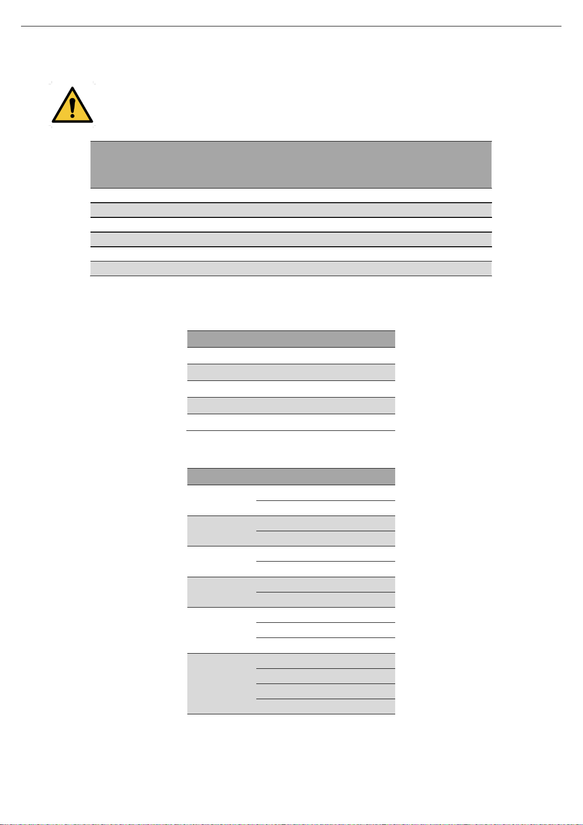
Technical Specifications
Pump size
Internal diameter
connection
[mm]
Maximum theoretical
sphere frame
[mm]
Recommended
máximum theoretical
sphere frame
[mm]
TLS 1-25
26
20,6
7
TLS 1-40
38
20,6
7
TLS 2-40
38
25,6
9
TLS 2-50
50
25,6
9
TLS 3-50
50
38,5
13
TLS 3-80
81
38,5
13
Pump size
Nm
lbf·ft
M6
10
7
M8
21
16
M10
42
31
M12
74
55
M16
112
83
Pump size
kW
Kg
TLS 1-25
0,55
36
0,75
39
TLS 1-40
0,75
40
1,1
44
TLS 2-40
1,1
59
1,5
63
TLS 2-50
1,5
64
2,2
74
TLS 3-50
2,2 / 3
121 4 126
5,5
156
TLS 3-80
3
124 4 130
5,5
159
7,5
166
9.3. SIZE OF PARTICLE
¡WARNING! Only soft particles.
<10% damage when using trilobe geometry
<2% damage when using wing lobe geometry
9.4. TIGHTENING TORQUES
9.5. WEIGHTS
24 INOXPA S.A.U. · 01.520.30.07EN · (0) 2019/04
Page 25
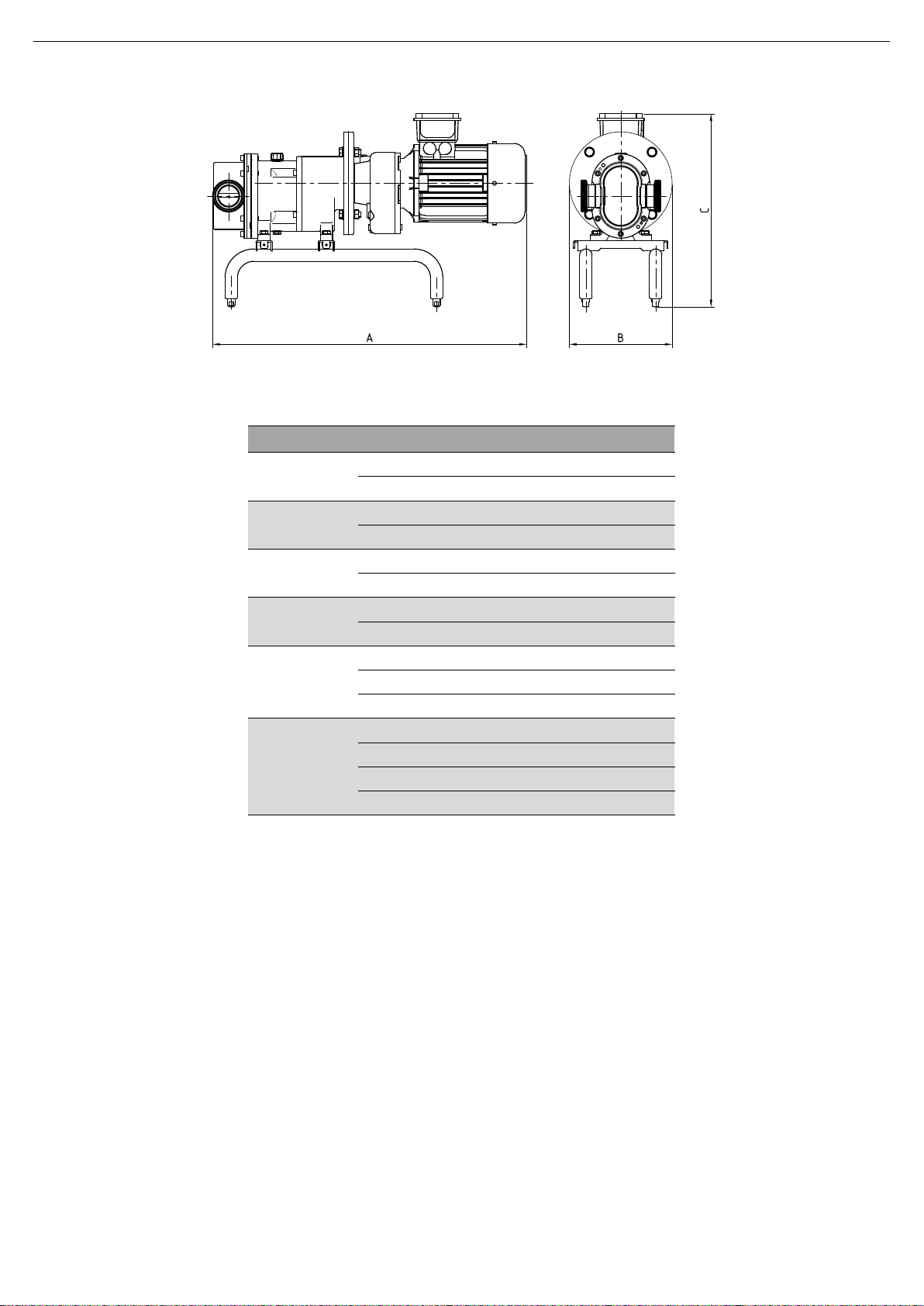
Technical Specifications
Pump size
kW
A
B
C
TLS 1-25
0,55
625
165
387
0,75
625
165
387
TLS 1-40
0,75
640
165
387
1,1
675
185
392
TLS 2-40
1,1
725
200
448
1,5
725
200
448
TLS 2-50
1,5
735
200
448
2,2
765
200
470
TLS 3-50
2,2 / 3
880
250
569
4
925
250
579
5,5
1010
270
604
TLS 3-80
3
905
250
569
4
955
250
579
5,5
1035
270
604
7,5
1035
270
604
01.520.32.0022
9.7. DIMENSIONS
INOXPA S.A.U. · 01.520.30.07EN · (0) 2019/04 25
Page 26
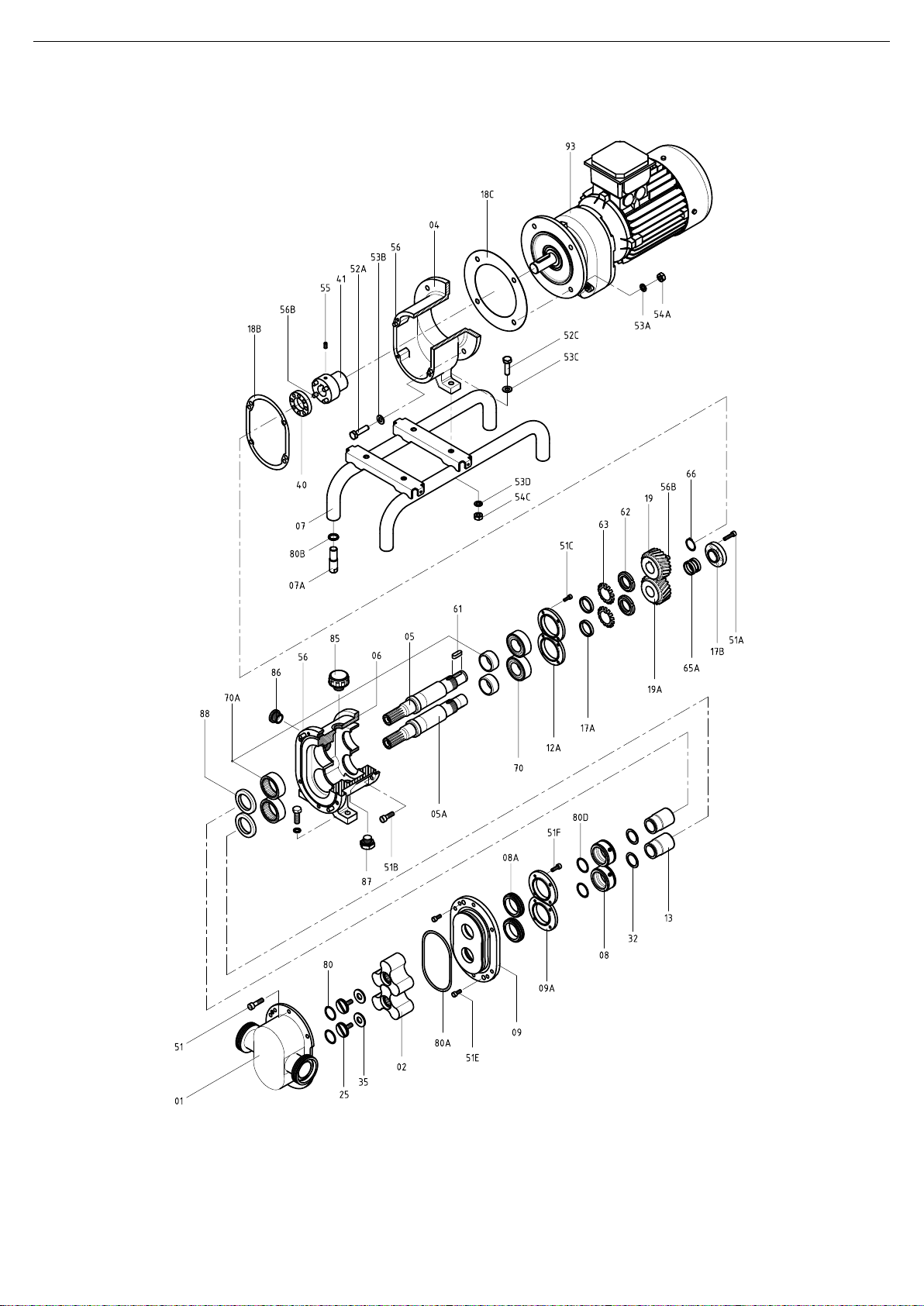
Technical Specifications
01.520.32.0018
9.8. EXPLODED DRAWING
26 INOXPA S.A.U. · 01.520.30.07EN · (0) 2019/04
Page 27

Technical Specifications
Position
Description
Quantity
Material
TLS 1
TLS 2
TLS 3
01
Pump casing
1
AISI 316L
02
Trilobe
2
AISI 316L
04
Lantern
1
GG-25
05
Drive shaft
1
AISI 316L
05A
Driven shaft
1
AISI 316L
06
Support
1
GG-25
07
Leg pump
1
AISI 304
07A
Adjustable leg
4
AISI 304
08
Mechanical seal -rotating part-
2
-
08A
Mechanical seal -stationary part-
2
-
09
Seal cover
1
AISI 316L
09A
Back seal cover
2
AISI 304
12A
Bearing stop flange
2
GG-25
13
Shaft sleeve
2
AISI 316L
17A
Driven shaft bushing
2
ST-52
17B
Dragging bushing
1 1 -
F-114
18B
Support joint
1
Klingerit
18C
Lantern joint
1
Klingerit
19
Drive shaft gear
1
F-154
19A
Driven shaft gear
1
F-154
25
Lobe screw
2
AISI 316L
32
Shim
2
AISI 316L
35
Lobe washer
2
AISI 316L
40
Flector
1
Poliamide
41
Coupling
1
F-114
50B
Allen screw
8 - -
51
Allen screw
6
A2
51A
Allen screw
8 6 -
8.8
51B
Allen screw
4 8 6
8.8
51C
Allen screw
8
8.8
51E
Allen screw
2
A2
51F
Allen screw
- 8 8
A2
52A
Hexagonal screw
4
A2
52D
Hexagonal screw
4
A2
53A
Flat washer
4
A2
53B
Spring washer
4
A2
53C
Spring washer
4
A2
53D
Flat washer
4
A2
54A
Hexagonal nut
4
A2
54C
Hexagonal nut
4
A2
55
Stud
1
8.8
56
Pin
2
A2
56A
Pin
2
Steel
56B
Pin
6 8 8
Steel
61
Key
1
Steel
62
Safety nut
2
Steel
63
Safety washer
2
Steel
65A
Conical tightening ring
1
Steel
66
Elastic ring
1
Steel
70
Ball bearings
2
Steel
70A
Needle bearings
2
Steel
80
O-ring
2
EPDM
80A
Joint
1
EPDM
80B
O-ring
4
NBR
80D
O-ring
2
EPDM
85
Oil plug
1
Plastic
86
Peephole
1
Plastic
87
Bleeder
1
Plastic
88
Lip seal
1
NBR
93
Drive
1
-
9.9. PARTS LIST
INOXPA S.A.U. · 01.520.30.07EN · (0) 2019/04 27
Page 28
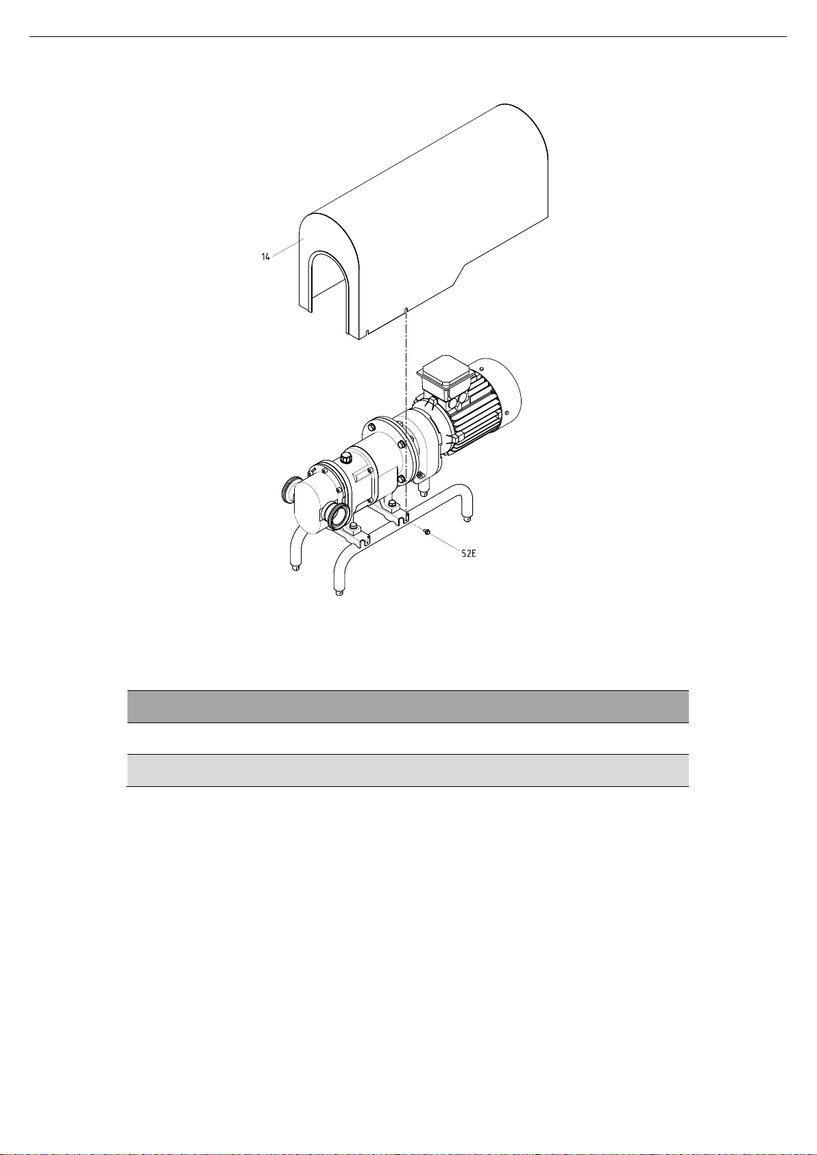
Technical Specifications
Position
Description
Quantity
Material
14
Shroud with joint
1
AISI 304
52E
Hexagonal flange screw
4
A2
01.520.32.0019
9.10. TLS SHROUD
28 INOXPA S.A.U. · 01.520.30.07EN · (0) 2019/04
Page 29
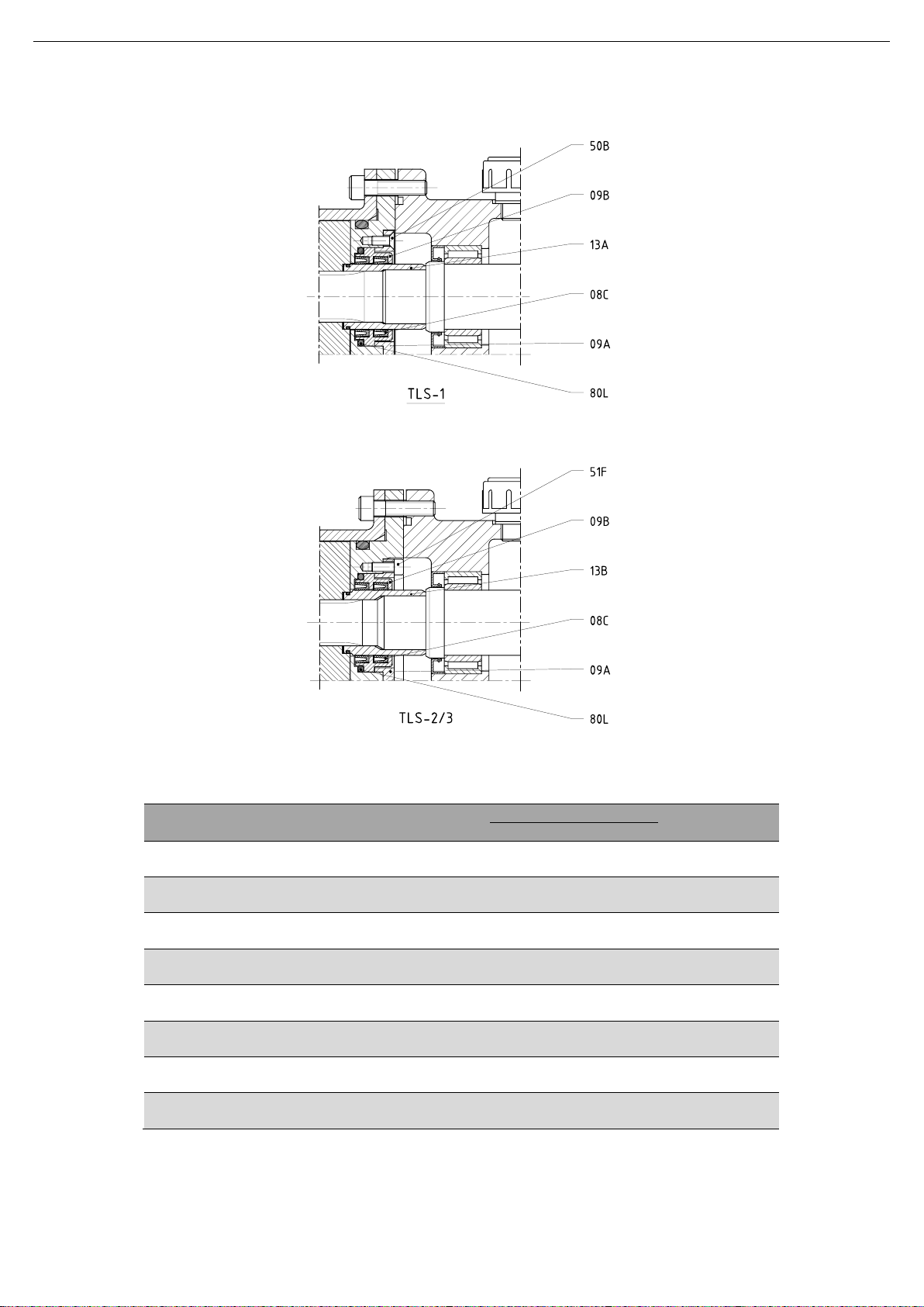
Technical Specifications
Position
Description
Quantity
Material
TLS 1
TLS 2
TLS 3
08C
Lip seal
4
FPM
09A
Back seal cover
2
AISI 316L
09B
Lip seal cover
2
AISI 316L
13A
Shaft sleeve
1 - AISI 316L
13B
Shaft sleeve
- 1 AISI 316L
50B
Countersink screw
8 - A2
51F
Allen screw
- 8 A2
80L
O-ring
2
EPDM
9.11. LIP SEAL
INOXPA S.A.U. · 01.520.30.07EN · (0) 2019/04 29
Page 30

NOTES
________________________________________________________________________________
________________________________________________________________________________
________________________________________________________________________________
________________________________________________________________________________
________________________________________________________________________________
________________________________________________________________________________
________________________________________________________________________________
________________________________________________________________________________
________________________________________________________________________________
________________________________________________________________________________
________________________________________________________________________________
________________________________________________________________________________
________________________________________________________________________________
________________________________________________________________________________
________________________________________________________________________________
________________________________________________________________________________
________________________________________________________________________________
________________________________________________________________________________
________________________________________________________________________________
________________________________________________________________________________
________________________________________________________________________________
________________________________________________________________________________
________________________________________________________________________________
________________________________________________________________________________
________________________________________________________________________________
________________________________________________________________________________
________________________________________________________________________________
________________________________________________________________________________
________________________________________________________________________________
________________________________________________________________________________
Page 31

NOTES
________________________________________________________________________________________
________________________________________________________________________________________
________________________________________________________________________________________
________________________________________________________________________________________
________________________________________________________________________________________
________________________________________________________________________________________
________________________________________________________________________________________
________________________________________________________________________________________
________________________________________________________________________________________
________________________________________________________________________________________
________________________________________________________________________________________
________________________________________________________________________________________
________________________________________________________________________________________
________________________________________________________________________________________
________________________________________________________________________________________
________________________________________________________________________________________
________________________________________________________________________________________
________________________________________________________________________________________
________________________________________________________________________________________
________________________________________________________________________________________
________________________________________________________________________________________
________________________________________________________________________________________
________________________________________________________________________________________
________________________________________________________________________________________
________________________________________________________________________________________
________________________________________________________________________________________
________________________________________________________________________________________
________________________________________________________________________________________
________________________________________________________________________________________
________________________________________________________________________________________
________________________________________________________________________________________
Page 32

01.520.30.07EN (0) 2019/04
How to contact INOXPA S.A.U.:
Contact details for all countries are
Continually updated on our website
Please visit www.inoxpa.com to access the information.
INOXPA S.A.U.
Telers, 60 – 17820 – Banyoles – Spain
Tel.: +34 972 575 200 – Fax.: +34 972 575 502
 Loading...