

INOXPA TLS Series, TLS 2-40, TLS 2-50, TLS 3-50, TLS 1-25 Installation, Service And Maintenance Instructions
...
INSTALLATION, SERVICE AND
MAINTENANCE INSTRUCTIONS
TLS LOBE PUMP
INOXPA, S.A.
c/Telers, 54 Aptdo. 174
E-17820 Banyoles
Girona (Spain)
Tel. : (34) 972 - 57 52 00
Fax. : (34) 972 - 57 55 02
Email: inoxpa@inoxpa.com
www.inoxpa.com

MANUFACTURER DECLARATION
LOBE ROTOR PUMP
TLS
2004
LOBE ROTOR PUMP
TLS
2004
According the EC directive about machines
The manufacturer:
INOXPA, S. A.
c/ Telers, 54
17820 Banyoles (Girona) - Spain
Hereby declares, that the pumps
Denomination Type Manufacturing year
Comply with the pertinent disposition, in the execution supplied by INOXPA, S.A. for
the incorporation in a machine or installation, or for the assembly with other machines
as a subunit of other higher order machine.
Harmonized norms used, particularly:
The machine above must not be put into service until the machinery into which it has
been incorporated have been declared in conformity with the EC Machinery Directive.
It must meet, particularly, the standards EN 294, EN 563, EN 809 y EN 953 in its
respective current editions.
Year of CE marking: CE 95
Banyoles, January 1995
98/37/CE, Annex II B
EN 292 part 1 and 2, EN 809
EC DECLARATION OF CONFORMITY
According the EC directive about machines
98/37/CE, Annex II A
The manufacturer:
INOXPA, S. A.
c/ Telers, 54
17820 Banyoles (Girona) - Spain
Hereby declares, that the pump
Denomination Type Manufacturing year
Are in conformity with the essential requirements of the Machinery Directive 98/37/CE
(latest modifications included) and according the following Council Direcitves and
harmonized norms:
- 72/23/CE Directive “low voltage”
- Norms EN 292 part 1 and 2, EN 809
Year of CE marking: CE 95
Banyoles, January 1995
1. Introduction
CHECK THE SHIPMENT.
The first thing to do when the pump is received is to check it and ensure that the contents conform to the shipping voucher.
INOXPA inspects all equipment prior to shipment, but it cannot guarantee that the merchandise reaches the user intact.
Therefore, the pump and any other article received should be checked and in the event the item in question did not conform to
specifications and/or was missing a/some part(s), the transportation company should prepare a report as soon as possible.
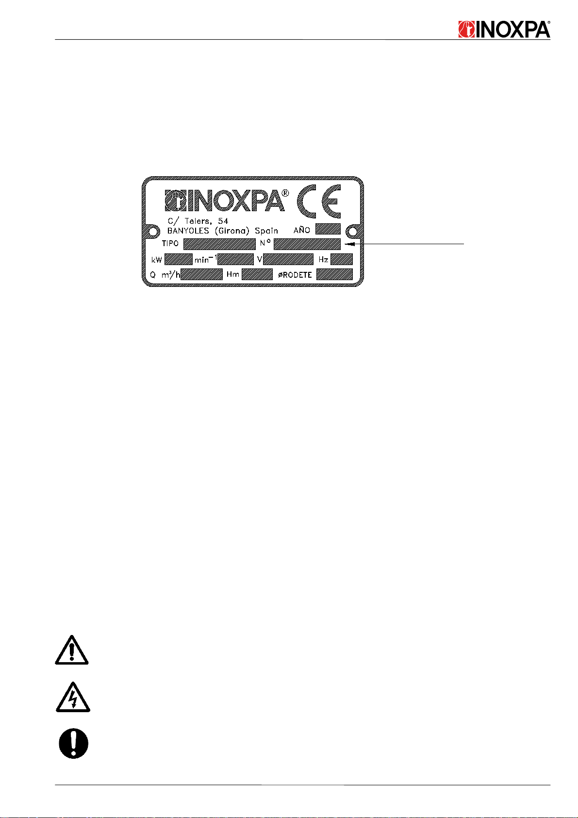
Each pump bears a serial number engraved on the plate. Indicate the serial number on all documents and correspondence.
Serial number
Figure 1.1: Serial number engraved on the manufacturer´s plate
If the pump is not put into service upon arrival, a complete revolution of the shaft should be made once a week.
INSTRUCTIONS MANUAL.
The information provided in the instruction manual refers to updated data.
We reserve the right to modify the design and/or manufacturing specifications of our products as required, devoid of any
obligation on our part to adapt any product supplied prior to such alteration.
The technical information made available in this instruction manual, together with the graphs and technical specifications
provided, shall continue to belong to us and should not be used (except for starting up this installation), copied, photocopied,
made available or otherwise given to third parties without our prior written consent.
INOXPA is reservation the right to modifying this instructions manual without previous notice.
START-UP INSTRUCTIONS.
This instruction manual contains vital and useful information for properly operating the pump and for keeping it in good
running condition. It also contains important instructions for avoiding possible accide nts and serious damage that could be
produced prior to its start-up and during its installation, thereby ensuring its handling in the safetest way possible. Please read
the instructions carefully before operating the pump and familiarize yourself with its operation, following very carefully the
instructions provided. We wish to stress the importance of being informed on how to perform the installation correctly. It is
extremely important to keep these instructions in a secure place close to the installation.
MAINTENANCE.
This pump, like any other machine, requires routine maintenance. Chapter 9, "Spare Parts", deals with the identification of the
spare parts. It is intended for the use of technical and maintenance personnel and for those persons responsible for supplying
spare parts.
OPERATING PRINCIPLES.
A. Safety.
This symbol indicates those safety instructions contained in this manual which when not followed co uld
jeopardize your safety
This symbol indicates potential problems with electrical safety.
This symbol indicates a compulsory measure to be taken by the user in compliance with specific
instructions which serve to guarantee operating safety and/or protection of the pump.
ED.10.12/98 1. TLS Introduction 1.1

B. Technical principles.
Quantity Symbol Unit
Dinamic viscosity
µ
V=µ/ρ with ρ=specific weight [Kg/dm
Kinematic viscosity
Only the dynamic viscosity is used in this manual.
p[bar]
Pressure
∆p
Pm [bar] - maximum pressure at discharge mouth (design pressure)
Unless otherwise indicated, in this manual pressure is understood to be relative pressure.
NPSH [m]
In this manual, NPSH = NPSHr (NPSH required for the pump).
NPSHr = the net pressure above the liquid vapour pressure at pumping temperature and
at the pump inlet connection required to avoid performance impairment due to cavitation
Net positive suction
head (NPSH)
at rated capacity. NPSHr is measured at the suction flange at the point where the capacity
drop = 4% of the rated capacity, and is corrected to the datum elevation.
NPSHa = the total suction pressure available from the system at the pump suction
connection, minus the vapour pressure if the liquid at pumping temperature. NPSH
available is calculated for the installation. It is the responsibility of the user to determine
this value.
mPa.s (=cP=Centipoise)
and V = kinematic viscosity
2
[mm
/s] = cSt = Centistoke
[bar] - differential pressure
NPSHa ≥≥≥≥ NPSHr + 0,5
3
]
Symbols.
It is absolutely necessary to place symbols on the pump, e.g., arrows which indicate the direction of rotation or other symbols
indicating connections to fluids. All of these symbols should be clearly visible and legible.
Training and experience.
The personnel who are responsible for the operation, maintenance, inspection and assembly of the equipment should have the
proper experience and training. The scope of their responsabilities and the supervision of the operators should be specifically
defined by the plant foreman.
If the operators did not have the required knowledge, they should be trained, which could be done by the manufacturer of the
machine or by the supplier on behalf of the shop foreman.
Furthermore, the shop foreman should make sure that the contents of the instruction manual are fully understood by the
operators.
In accordance with the instructions.
Any failure to comply with the instructions could lead to a hazard for the operators, the atmospheric conditions of the room,
and the machine, and it could lead to a loss to any right to make a claim for damages.
Such non-compliance could bring with it the following risks:
• Important operating failures of the machine / plant.
• Failure to comply with specific maintenance and repair procedures.
• Potential electrical, mechanical and chemical hazards.
• Atmospheric conditions in the room could be hazardous due to the release of chemical substances.
In accordance with the regulations governing safety at work.
The instructions contained in this manual should be followed for operating the pump, along with national regulations and any
other service and safety instructions made available by the shop foreman, so as to avoid accidents.
Safety instructions for handling .
If the machine's components, whether in a cold or warm state, constitute some hazard, then accidental contact with the same
should be avoided.
When the machine is operating, be sure that the rotating parts are protected by a shield.
In the event of a fire (e.g., mechanical seal) of hazardous fluids (e.g., explosives, toxic agents, hot products), the machine
should be emptied to prevent any risk to persons or to the ambient conditions. Existing regulations should be strictly adhered to.
Avoid any hazard which could be produced by the electrical circuits (e.g.: VDE specifications and regulations on the supply of
local energy services).
1. TLS Introduction 1.2 ED.10.12/98

Safety instructions for maintenance, inspection and assembly.
It is the shop foreman's responsibility to see to it that maintenance, inspection and assembly work is performed by qualified
personnel once they have become familiar with the subject; they should read this manual very carefully.
Work should only be done on this machine when it is stopped; it is extremely important that the procedure for stopping the
machine be followed as set forth in this manual.
Those pumps should be de-contaminated which may contain hazardous agents.
Upon completion of the work, re-install the safety and protection devices.
Prior to re-initiating the operation of the machine, the instructions given in the chapter on "Operating Principles" should be
read.
Changes without prior authorization and production of spare parts.
No modification can be made to the machine without the prior consent of the manufacturer. For your safety, use spare parts and
accessories authorized by the manufacturer.
The use of other parts exempts the manufacturer from any and all responsibility.
Unauthorized operations.
The machine's safety is only ensured if it is used properly in accordance with the instructions given in this manual.
The limits for values specified in the data sheet cannot be exceeded under any circumstances.
Any change in operating conditions can only be done with the prior written consent of INOXPA.
WARRANTY.
We wish to point out that any warranty issued will be null and void and that we are entitled to an indemnity for any civil
liability claim for products which might be filed by third parties if:
• o peration and maintenance work has not been done following the corresponding instructions; the repairs have not been
made by our personnel or have been made without our written authorization;
• modifications are made to our material without prior written authorization;
• the parts o r lubricants used are not original INOXPA parts/lubricants;
• the material has been improperly used due to error or negligence or have not been used according to the indications
and the intended purpose.
The General Delivery Terms which you have already received are also applicable.
INOXPA SERVICE.
In the event of doubt or should you require a fuller
explanation on particular data (adjustment, assembly,
disassembly...), please do not hesitate to contact us.
ED.10.12/98 1. TLS Introduction 1.3

2. Table of Contents
1. Introduction
Check the shipment ........................................................................................................... 1.1
Instruction manual .............................................................................................................1.1
Start-up instructions ..........................................................................................................1.1
Maintenance ...................................................................................................................... 1.1
Operating principles .......................................................................................................... 1.1
Safety ................................................................................................................................ 1.2
Warranty ........................................................................................................................... 1.3
INOXPA Service .............................................................................................................. 1.3
2. Table of Contents
3. General Information
Description ........................................................................................................................ 3.1
Principle of operation ........................................................................................................ 3.1
Noise ................................................................................................................................. 3.1
Application ........................................................................................................................ 3.1
Hygiene ............................................................................................................................. 3.2
Materials used in its construction ...................................................................................... 3.2
Field of application ...........................................................................................................3.2
Safety valve ....................................................................................................................... 3.3
Shaft sealing ...................................................................................................................... 3.4
4. Installation
General considerations ...................................................................................................... 4.1
Instructions for reception, transport and storage ............................................................... 4.1
Location ............................................................................................................................ 4.1
Stability ............................................................................................................................. 4.2
Handling ............................................................................................................................ 4.3
Electric motors .................................................................................................................. 4.3
Speed variators and reducers ............................................................................................. 4.4
Direction of rotation ..........................................................................................................4.4
Suction an discharge pipes ................................................................................................ 4.4
5. Start-up
General considerations ...................................................................................................... 5.1
Pre-start-up procedures...................................................................................................... 5.1
Cleaning ............................................................................................................................ 5.1
Start-up .............................................................................................................................. 5.1
Safety valve ....................................................................................................................... 5.2
6. Maintenance
General considerations ...................................................................................................... 6.1
Preparations ...................................................................................................................... 6.1
Conservation ..................................................................................................................... 6.1
External cleaning ...............................................................................................................6.1
Electrical installation ......................................................................................................... 6.2
Maintenance ...................................................................................................................... 6.2
Oiling ................................................................................................................................ 6.2
7. Operating Problems
ED.10.12/98 2. TLS Table of Contents 2.1

8. Disassembly and Assembly
General considerations ...................................................................................................... 8.1
Disassembly and assembly. Pump housing ........................................................................8.2
Disassembly of the lobes and the pump cover ...................................................................8.2
Mechanical seal and shaft sleeve........................................................................................ 8.2
Assembly of the shaft sleeve and the pump cover ............................................................. 8.3
Fitting the lobes ................................................................................................................. 8.3
Adjusting the lobes ............................................................................................................8.5
Changing the lip seals......................................................................................................... 8.6
Changing the drive ............................................................................................................8.6
9. Technical Information
Technical data ...................................................................................................................9.1
Frame of the particles ....................................................................................................... 9.1
Materials ............................................................................................................................9.2
TLS pump dimensions ....................................................................................................... 9.3
TLS pump with shroud dimensions ................................................................................... 9.4
TLS pump with pressure by-pass dimensions ....................................................................9.5
TLS 1-25/1-40 Parts diagram ............................................................................................ 9.6
TLS 1-25/1-40 Parts list .................................................................................................... 9.7
TLS 2-40/2-50 Parts diagram ............................................................................................ 9.8
TLS 2-40/2-50 Parts list .................................................................................................... 9.9
TLS 3-50/3-80 Parts diagram ............................................................................................ 9.10
TLS 3-50/3-80 Parts list .................................................................................................... 9.11
TLS 3-51/3-81 Parts diagram ............................................................................................ 9.12
TLS 3-51/3-81 Parts list .................................................................................................... 9.13
TLS shroud ........................................................................................................................ 9.14
Single mechanical seal ......................................................................................................9.15
PTFE Lip seal TLS 1..........................................................................................................9.16
PTFE Lip seal TLS 2..........................................................................................................9.17
PTFE Lip seal TLS 3..........................................................................................................9.18
INOXPA Lip seal ..............................................................................................................9.19
10. Cleaning and Disinfection
General considerations ...................................................................................................... 10.1
Hygiene .............................................................................................................................10.1
Safety in cleaning and disinfection .................................................................................... 10.2
2. TLS Table of Contents 2.2 ED.10.12/98

3. General Information.
DESCRIPTION.
The TLS lobes pumps by INOXPA are part of our wide range of positive displacement rotary pumps for viscous liquids.
The following models exist in the lobe pump range:
• The TLS normal flow rate pump suitable for pressures of up to 12 bar.
• The TLS with wider lobes, delivers a higher flow rate, and is suitable for pressure of up to 7 bar.
The TLS model has been specially developed to respond to all hygienic requirements in the food industry.
As regards hygiene, reliability and sturdiness, the complete range of lobes pumps satisfies all requirements set by the aforesaid
industry.
Its modular design enables optimal part interchange between the different pumps.
PRINCIPLE OF OPERATION.
The lobe pump is a positive displacement rotary pump. The top lobe is driven by the driving shaft. The lower lobe is located on
the driven shaft, and is driven via a helical gear. Both lobes rotate in synchronism without one touching the other. When the
pump is running they displace a set volume of liquid. Figure 3.1. shows how a lobe pump ope rates.
Figure 3.1: Operating principle
A: When the lobes rotate, the space on the suction side increases because one lobe moves away from the other, thus causing a
partial vacuum that draws the liquid into the pumping chamber.
B: Each lobe void is filled consecutively as the shafts rotate and the liquid is displaced towards the discharge side. T he small
clearances between the lobes, and between the lobes and the walls of the pump body duly cause the spaces to be rather well
closed.
C: The pump body is completely full and the liquid leaks through the meshing of the lobes, knocking against the space walls
so as to thus complete the pumping action.
NOISE.
The lobes pumps are rotary displacement pumps. Owing to the contact between the internal parts, the pressure variations, etc.
They make a louder noise than centrifugal pumps. This noise must be taken into consideration when installing these pumps.
When the noise level in the operating area exceeds 85 dB(A), a special protection shall be installed.
APPLICATION.
The main advantage of the INOXPA lobe pump is its capacity to pump a great variety of viscous liquids, from 1 mPa.s up to
100.000 mPa.s
Furthermore, it is capable of pumping liquid products that require very careful handling and liquids that contain soft solids thys
causing only a minimum degradation of same.
HYGIENE.
Special attention has been given to hygiene and cleaning requirements in the construction of the pump. The number of grooves
and dead spaces have been limited to an absolute minimum. Furthermore, no liquid can enter between the lobes and shafts.
The TLS lobes pumps by INOXPA have been approved by the American 3A Standard Authorities.
ED.10.12/98 3. TLS General Information 3.1

MATERIALS USED IN ITS CONSTRUCTION.
All pump parts which are in contact with the product are stainless steel, or are made of tasteless and odorless materials. This
makes the pump resistant to corrosion and avoids contamination of the liquid being pumped
It is necessary to check and verify that the materials (of the parts in contact with the product) are
adequate for pumping a product which is specifically fo r human consumption.
Table 3.1: Parts in contact with the liquid
Part Material
Pump housing AISI-316 (1.4408)
Pump cover AISI-316 (1.4408)
Trilobe AISI-316 (1.4401)
Lobe screw AISI-316 (1.4401)
Shaft sleeve AISI-316 (1.4401)
Table 3.2: Parts which can be in contact with the liquid
Part Material
Shaft AISI-316 (1.4401)
FIELD OF APPLICATION.
Figure 3.2: Field of application
The field of application for each type of pump is limited. The pump was selected for certain
pumping conditions at the time that the order was passed. INOXPA assumes no responsibility
for damages that may arise in the event that the information made available by the purchaser is
incomplete (nature of the liquid, viscosity, r.p.m. ...).
Do not use the pump for applications other than those for which it has been specified on
purchase and installation. No modifications can be made without previously consulting with
INOXPA and without the latter's written consent. A correct application shall take into account
the following: the viscosity of the product, its properties, purity, temperature, suction and
discharge pressure, r.p.m. ...
When the pump is used in a pumping unit or in an environment for which the pump has not
been designed, the operator and the material may be exposed to hazard. Consult INOXPA in
case of doubt prior to use.
3. TLS General Information 3.2 ED.17.10/00

Refer to Table 3.3 and the corresponding notes for value limits (viscosity, temperature, pressure...).
Table 3.3 : Field of application.
TLS
50 Hz 60 Hz
68 litres 95 litres
Theoretical flow rate litres /100 min
-1
Maximum flow rate 29 m3/h 41 m3/h
Maximum pressure 12 bar 7 bar
Maximum connections 50 mm 80 mm
Maximum temperature 110 °C 110 °C
Maximum viscosity (recommended) 100.000 mPa.s. 100.000 mPa.s.
Maximum speed 950 min
-1
950 min
-1
WARNING The following limit ought to be consi dered for the:
- Single mechanical seal: 2500 mPa.s (Newtonian liquid)
The maximum viscosity allowed will depend on the nature of the liquid and the sliding speed of
the seal faces. Consult INOXPA should the viscosity be still greater.
SAFETY VALVE.
The positive displacement lobes pumps must be protected from excess pressure when they are
operating. Consequently, all the TLS lobes pumps can be fitted with a stainless steel safety valve or a
safety by-pass.
Protection.
This valve protects the pump and prevents excessively high pressure arising in the circuit. It reduces the differential pressure
(p) between the intake and discharge, but not the maximum pressure within the plant.
Do not use the safety valve to protect the system from excess pressure. It is designed to protect the
pump only as it is not a safety outlet.
Operation principle
The safety by-pass valve is located in the housing and prevents excess pressure arising inside the pump. For example, when the
pump's discharge mouth is clogged and the liquid cannot be pumped out, too high a pressure can cause serious damage to some
of the pump's parts. The safety valve opens a passage from the pump's discharge side to its suction side: an escape route,
redirecting the flow again to the suction side whenever specifically high pressure levels are reached.
The safety valve/by-pass is only effective in one direction of rotation.
If the safety valve operates, this will mean that the equipment is not working properly. The pump
should be disconnected immediately. Identify and solve the problem before re-starting the pump.
Remember that the safety valve in the pump is not able to be used to regulate the flow rate.
If the safety valve is not fitted in the pump, other steps should be taken to protect the pump from excess
pressure.
Setting.
The safety valve can be adjusted to any determined pressure, according to the type of pump being used.
SHAFT SEALING.
The following options for the mechanical seal are applicable to the entire range of pumps.
• Single mechanical external seal.
Table 3.4: Materials for faces exposed to friction and external mechanical seal elastomers
Rotating part Stationary part Elastomers
standard stainless steel graphite nitril
option silicon carbide silicon carbide viton
ED.10.12/98 3. TLS General Information 3.3

4. Installation.
GENERAL CONSIDERATIONS.
This manual provides basic instructions which should be taken into account when proceeding to install the pump. It is of utmost
importance that the plant foreman reads this manual before installation.
The instructions include pertinent information which will enable you to install your pump / pumping unit correctly. The manual
also contains important instructions for preventing eventual accidents and serious damage which could occur prior to start up
and during the installation.
It is imperative to put warning markers on the pump, e.g., arrows which indicate the direction of rotation or symbols indicating
fluid connections. All these warnings should be clearly visible and legible.
Any failure to comply with the instructions could result in a risk for the operators, the environment and the machine, and could
result in the loss of any right to make a claim for damages.
INSTRUCTIONS UPON DELIVERY, FOR TRANSPORT AND STORAGE.
When the machine arrives, read the instructions on page 1 of the chapter titled "Introduction".
TLS pumps and pumping units are often too heavy to be stored manually. Use an adequate means of
transport. Use the points which are indicated in the drawing for lifting the pump.
Only authorized personnel should transport the pump. Do not work or walk under heavy loads.
Figure 4.1: Lifting the pump.
LOCATION.
Piping.
Place the pump or pumping unit as close as possible to the suction tank (refer to chapter, "Pump Installation"), and if possible
below the level of the liquid or even lower with regard to the tank so that the static manometric suction head is at its maximum.
Place the suction and discharge piping in straight runs with a minimum of elbows and fittings in order to reduce to the greatest
extent possible any loss of head caused by friction. This improves the suction conditions, thereby providing maximum
performance of the pump.
Accessibility.
Place the pump so that access can be had to the pump and to the drive units so as to make inspections and revisions. Leave
sufficient space around the pump / pumping unit for proper inspection, separation of the pump from other units and for
maintenance operations. In order to disassemble the TLS pump you should leave sufficient space in front of and behind it.
(Chapter 9 deals with the dimensions).
Place the pump / pumping unit with sufficient space for the lifting equipment if the components or the total weight of the unit
exceed 22 kg.
Place the pump / pumping unit near the drain on the floor.
It is very important to be able to gain access to the pump or pumping unit connecting device (even when it is operating).
ED.10.12/98 4. TLS Installation 4.1

Weights.
PUMP TYPE
TLS 1 – 25
TLS 1 – 40
TLS 2 – 40
TLS 2 – 50
TLS 3 – 50
TLS 3 – 51
TLS 3 – 80
TLS 3 – 81
MR = shrouded pump.
MB = unshrouded pu mp.
Drive
Power
[kW]
0,55 37,5 31,5
0,75
1,1 44,5 38,5
1,5
0,75 SK 01/80 39,5 33,5
1,1 45,5 39,5
1,5
1,1 56 49,5
1,5
2,2 SK 20/100
1,5 SK 20/90 61,5 55
2,2 SK 20/100
2,2 110 100
3
4 SK 25/112
5,5 SK 33/132 71 61 155 145
3 SK 30/100 120 110
4 SK 30/112 131 121
5,5
7,5
Speed
reducer type
SK 01/80
SK 01/90
SK 01/90
SK 20/90
SK 25/100
SK 33/132
Pump without
drive
MR
[Kg.]
20,5 14,5
21,5 15,5
28 21,5
29,5 23
71 61
74 64
74 64 169 159
MB
[Kg.]
Pump with
drive
MR
[Kg.]
38,5 32,5
48,5 42,5
49,5 43,5
60 53,5
63 56,5
64,5 58
115 105
126 116
158 148
[Kg.]
MB
Outdoor installation.
The TLS pump can only be installed out of doors if there is a roof covering it or, if permitted, a special installation is to be
made. Consult INOXPA prior to installation.
Indoor installation.
Place the pump so that the motor is properly ventilated. Prepare the motor to be started according to the instructions provided
by its manufacturer.
A suitable connection should be used when inflammable or explosive liquids are pumped. Connect the
components of the unit with grounding jumpers in order to reduce the danger from static electricity.
Use explosion-proof motors in accordance with local regulations.
Excessive temperatures.
Depending on the fluid to be pumped, high temperatures can be reached inside and around the pump.
Over 70º C, the operator should take protective measures and place warning notices advising of the
danger which exists if the pump is touched.
The type of protection selected should not isolate the pump entirely. It should allow for the bearings to
be cooled more efficiently and for the bearings to be lubricated.
STABILITY.
Foundation.
Prepare the foundation so that the pump is level and well supported. Its emplacement should be rigid, horizontal, flat and
resistant to vibrations, so as to avoid any warping (if the pump's alignment is maintained its operation is ensured during start-up).
Piping Installation
Piping can be installed horizontally and vertically, provided that the pump remains leveled.
4. TLS Installation 4.2 ED.10.12/98

HANDLING.
If the pump is supplied without a drive, the purchaser/user is responsible for the pump's start-up and
assembly.
Starting torque.
The starting torque of the positive displacement pumps is almost identical to the rated torque. Make sure that the motor's rated
torque is sufficiently high, but check that it does not exceed the maximum torque allowed on the pump shaft (see technical
specifications). Consequently, choose a motor with a capacity 25% greater than the power absorbed by the pump.
ELECTRIC MOTORS.
Regulations.
Prior to connecting an electric motor to the power supply, check local regulations on electrical safety and also refer to the EN
60204-1 standard.
Let qualified personnel perform the connection of electrical motors. Take the necessary steps to
prevent faults in the connections and wiring.
Automatic breaker.
In order to work on the pump without hazards, an automatic breaker should be installed as close as possible to the pump. The
use of a grounding switch is also recommended.
The pumps switch gear should comply with current regulations, as set forth in the EN 60204-1
standard on electrical safety.
Protection of the motor against overloads.
In order to protect the motor from overloads and short circuits, the use of thermal or magnetic relays is recommended. Adjust
these relays to maximum rated current values as indicated on the data plate of the motor.
Electrical diagram.
Connection U=...
3x220 3x380
motor
220/380
380
∆
-
∆
Figure 4.2: TLS pump electrical connections
ED.10.12/98 4. TLS Installation 4.3

Connection.
Consult the supplier's instructions prior to connecting the motor to the power supply.
For single-phase motors, use motors with an increased starting torque.
Ensure a starting torque which is sufficiently high for motors controlled by a frequency converter, and provide for adequate
cooling at low speeds. If necessary, install an independent fan.
The electrical equipment, the terminals and the control system components can continue to carry
current when disconnected. Any contact with them can endanger the safety of the operators or cause
irreparable damage to the material.
SPEED VARIATORS AND REDUCERS.
If using speed variator or reducer in the pumping unit, consult the supplier's instruction manual, and the directives numbered
under the section "electric motors".
DIRECTION OF ROTATION.
The direction of rotation determines the location of the pump's suction and discharge mouths.
The standard rotation direction is clockwise looking from the rear end of the motor, displacing the fluid from right to left (see
figure 4.3).
However, it is easy to invert the rotating direction and therefore vary the fluid's flow direction.
Make sure that the pump rotates in the direction indicated on the plate. If the pump rotates in the
wrong direction it could cause serious damage.
Figure 4.3: direction of rotation
SUCTION AND DISCHARGE PIPES.
Excessive forces and moments on pump connections, caused by the piping, could result in mechanical damage to the pump or
pumping unit.
These pipes should be connected in a straight line, without leaving spaces between connections and the faces of parallel
connections. Provide for adequate anchoring devices and make sure that they are not tensed too much when the pump is
operating.
When hot liquids are pumped, pay attention to thermal expansion; if this is the case, use expansion joints.
Once the connection has been made, check that the shaft can turn freely.
Pipes.
Use pipes with a diameter which is equal to or greater than that of the pump's connections. If the liquid to be pumped is
viscous, the loss of head from the suction and discharge pipes can increase considerably. Other pipe components such as
valves, elbows, filters and foot valves, can also cause a loss of head.
For this reason, the diameters and the length of pipes and other components should be selected so as not to cause any
mechanical wear to the pump/pumping unit, operating within the minimum pressure limits allowed for the suction (refer to
NPSH graph), the maximum working pressure (refer to chapter 3, "Field of Application"), and without surpassing the rated
motor power.
4. TLS Installation 4.4 ED.10.12/98

Suction pipe.
Liquids should be introduced into the pump from a higher level than that of the pump; the pipe should be inclined in its path to
the pump and be devoid of air pockets.
A diameter which is too small, a suction pipe which is too long, or a filter that is too small or clogged,
will lead to a greater loss of head and thus the NPSH available (NPSHa) can become less than that
required (NPSHr). Cavitation may occur, causing noise and vibrations. Under such circumstances,
the pump or the pumping unit may be mechanically damaged.
If a filter is installed in the suction mouth, the loss of head in the suction pipe should be constantly checked. Also make sure
that the instake pressure at the suction mouth of the pump is sufficiently high (see NPSH).
When the pump is operating in both directions, the loss of head must be calculated for both
directions.
Check the tension of the suction pipe after its connection.
Self-priming process.
In general terms --if the self-priming pr ocess is followed-- the pump ought to contain sufficient liquid to fill the internal
recesses and the void spaces thus enabling the pump to create a pressure difference.
However, if low viscosity fluids are to be pumped, a foot valve of the same or greater diameter as that of the suction pipe
should be installed; alternatively, the pump can be installed with a "U" shaped piping.
The use of a foot valve is not recommended for pumping viscous liquids.
In order to eliminate air and gases from the suction pipe, the counter-pressure on the discharge pipe should be reduced. When
the self-priming process is used, the pump's start-up should be done by opening and emptying the discharge pipe which allows
the air and gases to escape at a low counter-pressure.
Another possibility involves long pipes or when a check valve is installed in the discharge pipe; it is also possible to install a
by-pass with a shut-off valve on the discharge side of the pump. This valve shall be opened in the case of priming and will
allow air and gases to escape at a minimum counter-pressure.
The by-pass should not lead back to the intake orifice but to the supply tank instead.
Figure 4.4: View of the self-priming process.
ED.10.12/98 4. TLS Installation 4.5

Shut-off valves.
For a proper maintenance, the pump should be isolated. This isolation can be obtained by installing shut-off valves in the
suction and discharge pipes of the pump.
These valves should be able to open completely, both for suction and for discharge, up to the full passage of suction and
discharge pipes (ball-valves or sluice valves are preferable).
When the pump is started up, the shut-off valves should be completely open.
The flow rate should never be regulated by closing the shut-off valve in the suction or
discharge pipe.
The flow rate is to be regulated by increasing or decreasing the pump's speed or by using a by-pass which re-directs the flow to
the supply tank.
Filters.
Foreign particles can seriously damage the pump. Avoid the entry of these particles by installing a filter.
When selecting a filter, bear the diameter of the screen openings in mind so that loss of head will be minimal. The filter
diameter should be three times greater than that of the suction pipe.
The filter should be placed in such a way that it does not interfere with maintenance and cleaning operations. Be sure that the
density of the liquids is appropriate and that they can be filtered easily.
Refer to Chapter 9 ("Technical Specifications") for information on the maximum frame permitted for foreign particles.
4. TLS Installation 4.6 ED.10.12/98

5. Start-Up.
GENERAL CONSIDERATIONS.
The pump can be started up so long as the instructions given in chapter 4 ("Installation") have been followed.
Prior to start-up, the persons responsible for the operation must be duly informed of the pump /
pumping unit's operation and the safety instructions. This inst ruct ion manual should be available to
personnel at all times.
Prior to start-up, check the pump or pumping unit for any possible failure. If a failure is fo und, t he
plant foreman should be notified immediately.
Also consult the section "Dimensions" in chapter 9.
PRE-START-UP PROCEDURES.
• Prepare the motor or other drive for operating according to instructions provided by motor manufacturer.
• Check the electrical supply to see that it matches the motor nameplate rating.
• Make sure all product contact parts and seal parts are clean. If necessary dismantle and clean by hand (Follow instructions
of chapter 8).
• Check that the pump is protected from the ingress of foreign bodies are installed.
• The interior of the pump, the suction and the discharge pipes must be absolutely free of all foreign material.
• Check if all main and all piping is connected, tight and leak free.
• Remove the transport security of the oil plug of reducer.
• Check oil level of the pump. Add correct grade of oil as necessary to maintain level in centre of oil sight glass (in the case
of first start-up: pumps are shipped with oil in the gearbox, nevertheless this check may be skipped).
Do not overfill! See chapter “Maintenance”.
Prior to start-up, substitute the blind stopper for transportation, by the stopper of gases exit
supplied in a bag of plastic.
CLEANING.
Prior to start-up, check to see that the pipes and the pump are completely clean and devoid of weld
spatterings or other foreign particles.
Consult chapter 10 (cleaning and disinfection) on how to properly clean your TLS pump and the cleaning methods and liquids
which should be used.
START-UP.
• Completely open the shut-off valves in the suction and discharge pipes.
• If the liquid does not flow into the pump, fill it with the liquid to be pumped..
The pump should never rotate when empty.
• Check to see if the pump can be started up safely.
• Start the pump.
• Check to see whether the absolute intake pressure is sufficient, so that no vapour can be emitted inside the pump. Refer to the
curve for the minimum pressure required above the vapour pressure (NPSH).
• Control the discharge pressure.
A shut-off valve installed in the suctio n pipe should not be used to regulate the flow ra te. It must
remain completely open during the pump's operation.
ED.10.12/98 5. TLS Start-Up 5.1

SAFETY VALVE.
The safety valve opening pressure setting is done in the INOXPA workshop. However, the valve's opening pressure depends on
the fluid to be pumped, its viscosity, its r.p.m......, and so before starting-up the pump, the operator ought to adjust the safety
valve's opening pressure.
The safety valve setting.
When the safety valve setting is not shown on a pump thus equipped, the valve has been adjusted tot he pump's maximum
operating pressure. The operator must check this by observing the position of the pressure nut (37). When the pressure nut is
situated at the lower end of its travel, the valve has been set at the pump's maximum pressure.
To obtain the correct opening pressure, the following procedure should be followed:
• Loosen the counternut (37A).
• Using a spanner, turn the pressure nut (37) to the left to reduce the sp ring tension, and t hus obtain the required openi ng
pressure.
• If the correct opening pressure has been obtained, tighten the counternut (37A).
When checking the safety valve also make sure the pump's pressure will NEVER exceed the pressure
setting + 2 bar.
When the safety valve does not work properly, the pump must be taken out of service immediately.
The valve must be inspected by an INOXPA service technician.
Figure 5.1: Safety valve
5. TLS Start-Up 5.2 ED.10.12/98

6. Maintenance.
GENERAL CONSIDERATIONS.
Inadequate, wrong or improper maintenance could result in the faulty operation o f the pump, high
repair costs, and breakdown in the long run. For this reason the instructions given in this chapter
should be followed.
During maintenance operations which are performed on the pump, whether due to inspections,
preventive maintenance or the movement of the installation, the procedures indicated should always be
followed.
Failure to comply with these instructions could endanger the operator and/or seriously damage the
pump or pumping unit. Maintenance work should only be done by qualified personnel. Wea r
appropriate clothing which provides adequate protection against high temperatures and hazardous
and/or corrosive fluids. Make sure that the personnel read the entire instruction manual and, in
particular, indicate to them the chapters which refer to work which needs to be done. INOXPA does
not assume responsibility for accidents and damage which might occur as a result of any failure to
comply with the instructions indicated herein.
PREPARATION.
Work area.
Provide for a clean work area; some parts require very careful handling and others are machined to close tolerances.
Tools.
Use tools which are designed for the purpose for which they are to be used in maintenance and repair work. Use them properly.
Disconnection.
Before be ginning maintenance and inspection work, di sconnect the pump.
Decompress the pump and the pumping unit.
If the fluid to be pumped allows for it, let the pump cool down until it reaches room temperature.
Safety.
Do not let the motor start if work needs to be done on the pump. This is very important when electric motors are involved
which are started by remote control.
Follow the procedure outlined below:
• Place the pump switch in the "Off" position.
• Disconnect the pump from the power supply.
• Block the electrical control panel or put a warning notice on it.
• Remove the fuses and take them with you to the work area.
• Do not begin maintenance work until the pump has completely stopped.
CONSERVATION.
Should the pump be taken out of service for a long period of time:
• First of all, empty the pump.
• Apply VG46 mineral oil to the internal parts.
• The pump should be worked on for a brief period of time once a week or the shaft rotated manually. This ensures the
correct circulation of the protective oil.
EXTERNAL CLEANING.
Attempt to keep the exterior of the pump clean at all times. This helps in inspection work and keeps warning notices visible.
Make sure that cleaning products do not get into the motor's ball bearings. Cover all parts which should not enter into contact
with the cleaning fluid.
The cleaning products should not come into contact with the lip seals.
Do not spray hot parts of the pump with water as some components could crack due to quick cooling
and the fluid inside the pump could spill out.
ED.10.12/98 6. TLS Maintenance 6.1

ELECTRICAL INSTALLATION.
Maintenance work on electrical installations can only be done by qualified personnel and only when
the power supply has been cut off. Caref ully follow national safet y regulations.
Also abide by the regulations referred to above if you are working while the power supply is still connected.
Check to see whether the electrical materials to be cleaned are well protected (for example, IP 54
indicates protection against dust and water spray but does not include protection against pressure
water jets).
Refer to EN 60529. Choose an appropriate method of cleaning electrical materials.
Replace defective fuses with new ones having the prescribed amperage.
On finishing each maintenance operation, check the electrical installation components to see if they are defective and repair
them if necessary.
MAINTENANCE.
Periodically check suction and discharge pressures.
In general, a mechanical seal does not require any maintenance; however, the seal should never be made to work in dry state.
Should a leak occur, replace the seal.
OILING.
The gears and bearings are oiled by immersion in an oil bath (see table 6.1. to the quantity).
The pumps are supplied with oil. Before commissioning the pump, the oil sump must be filled up to the level in the middle of
the peephole.
DO NOT POUR TOO MUCH OIL INTO THE SUMP ! Leave the pump switched off for a while and then re-check the oil
level; if necessary, add a little oil. The first oil change must be carried out after 150 hours of operation. Afterwards, it can be
changed every 2500 operating hours or at least once a year when operating under normal conditions.
Regularly check the oil level, for example, weekly or every 150 operating hours.
Oils for environment temperatures of 5 to 50ºC: SAE 90 or ISO VG 220.
Table 6.1: quantity of oil in each support
Types
Quantity of oil in
the support (l.)
TLS 1 0,75
TLS 2 1
TLS 3 2
6. TLS Maintenance 6.2 ED.10.12/98

7. Operating Problems.
Problems
Overloading of motor
Insufficient discharge flow rate
No pressure on the discharge side
Irregular discharge flow rate/pressure
Noise and vibrations
The pump gets cl ogged
Overheating of pump
Abnormal wear
Leak through mechanic al seal
Probable causes Remedies
Wrong rotation direction Invert the rotation direction
1
Insufficient NPSH Increase available NPSH:
2
Pump not purged Purge or fill
3
Cavitation Increase suction pressure ( see 2)
4
The pump sucks in air Check suction pipe and all its connections.
5
Suction pipe clogged Check the suction pipe and filter(s), if any.
6
Wrong setting of safety valve Check the safety valve's setting
7
Discharge pressure too high If necessary, reduce the loss of head by increasing the
8
Viscosity of the liquid is too high - Reduce the pump speed
9
10
11
12
13
14
15
16
17
18
19
20
21
22
23
24
Viscosity of liquid too low. - Increase the pump speed
Temperature of liquid too high. Reduce the temperature by cooling the liquid.
Pump speed too high Reduce the pump speed
The lobes are worn Replace the lobes
Pump speed too low Increase the pump speed
Worn bearings Replace the bearings, check the pump
Worn or damaged mechanical seal Replace the seal
O-rings not the right ones for the liquid Fit the proper O-rings; check with the supplier.
Worn gears Replace and readjust the gears
Insufficient lubricating oil level Fill up with oil
Unsuitable lubricating oil Use an appropriate oil
The lobes rub - Reduce the temperature
Tension on the pipelines Connect the pipelines to the pump free of tensions
Foreign bodies in the liquid Insert a filter in the suction pipe
Mechanical seal spring tension too low Adjust as indicated in this manual
Probable Causes
8, 9, 12, 15, 19, 20, 21, 22.
2, 4, 5, 7, 8, 9, 10, 11, 13, 14.
1, 2, 3, 6, 7.
2, 4, 5, 6, 9, 12.
2, 4, 5, 6, 7, 8, 9, 11, 12, 13, 15, 18, 19, 20, 21, 22, 23.
8, 9, 11, 15, 18, 19, 20, 21, 22, 23.
7, 8, 9, 11, 12, 15, 19, 20, 21, 22.
4, 5, 11, 15, 18, 22, 23.
16, 17, 24.
- Rise the suction tank
- Lower the pump
- Reduce the speed
- Increase the diameter of the suction pipe
- Shorten and simplify the suction piping.
diameter of the discharge pipe
- Reduce the viscosity, for example, by
heating the liquid..
- Increase the viscosity, for example, by cooling the
liquid.
- Reduce the discharge pressure
- Adjust the play
and align the coupling
If the problems persist stop using the pump immediately. Contact the pump manufacturer or his
representative
ED.10.12/98 7. TLS Operating problems 7.1
.

8. Disassembly and Assembly.
GENERAL CONSIDERATIONS.
The assembly and disassembly of the pumps should only be done by qualified personnel. Make sure that the personnel read
carefully this instruction manual and, in particular, those instructions which refer to the work they will perform.
Incorrect assembly or disassembly may cause damage in the pump's operation and lead to high repair
costs and a long period of down-time.
INOXPA is not responsible for accidents or damages caused by a failure to comply with the instructions
in this manual.
Preparations.
Provide for a clean working environment as some parts, including the mechanical seal, require very careful handling and others
have close tolerances.
Check that the parts which are used are not damaged during transport. When doing this, you need to inspect the adjustment
edge, the butted faces, the tight fit, burrs, etc.
After each disassembly, carefully clean the parts and check for any damage. Replace all damaged parts.
Tools.
Use the proper tools for assembly and disassembly operations. Use them correctly.
Tightening torque.
Table 8.1: Tightening torque.
Material
8.8 6 10 25 49 86 135 210 290 410
A4 5 9 21 42 74 112 160 210 300
M5 M6 M8 M10 M12 M14 M16 M18 M20
Tightening torque N.m.
Cleaning.
Before disassembling the pump, clean it on the outside and on the inside.
NEVER clean the pump by hand when it is running.
Safety.
Prevent the motor from starting if you need to work on the pump.
Take steps to ensure that the motor cannot be started if the pump housing has been removed, for example, for cleaning
operations.
NEVER cause the pump to run without the housing.
Disconnection.
Before beginning disassembly and assembly work, disconnect the pump. Decompress the pump and the
pumping unit.
If the fluid in the pump allows for it, let the pump cool off until reaching room temperature.
Electrical safety.
Prevent the motor from starting if you need to work on the pump. This is very important when working with electric mot7ors
that are started by remote control.
Follow the procedure outlined below:
• Place the pump switch in the "Off" position.
• Disconnect the pump from the control panel.
• Block the electrical control panel or put a warning notice on it.
• Remove the fuses and take them with you to the work area.
• Do not begin disassembling or assembling until the pump has completely stopped.
ED.10.12/98 8. TLS Disassembly and Assembly 8.1

DISASSEMBLY AND ASSEMBLY.
PUMP HOUSING.
• Close the suction and discharge valves.
ATTENTION! The liquid can spill out when the pump housing is removed.
• Remove the Allen screws (51).
• Check to see that the O-ring (80A), located in the pump cover (09), is still in good condition.
• Make sure that the O-ring is not inverted when inserted.
• Once the pump housing is assembled, the Allen screws must be tightened (crosswise).
DISASSEMBLY OF THE LOBES AND THE PUMP COVER.
Remove the pump housing as indicated in the foregoing section.
• Remove the lobe screws (25) using a wrench, as shown in figure 8.1. These screws are threaded to the right. Wooden or
nylon blocks can be placed between the lobes to stop them from rotation (blocks position: one to the left in front of the top
lobe screw and the other to the right in front of the lower lobe screw).
• Check that the O-ring (80) is still in good condition.
Figure 8.1: Wrench
• Loosen the Allen screws (51E) that attach the pump cover (09) to the support. There are two notches to loosen the pump
cover, for example, using a screwdriver. Two pins (56) are used to centre the cover.
• Press the notches so that the both lobes (02) and the pump cover are loosened. If necessary, use a suitable tool.
• When the Allen screws (51E) have been removed, the lobes and the pump cover can also be taken apart. The rotating part
of the mechanical seal (08) remains situated in the shaft sleeve (13).
MECHANICAL SEAL AND SHAFT SLEEVE.
• One time the pump cover (09) has been disassembled, as indicated in the foregoing section, take out the seal cover (09A)
- the stationary part of the mechanical seal (08A) comes out of the pump cover -. Measures have been taken to avoid that this
face could rotate simultaneously with the shaft.
• Loosen the screws (50B -support 1-, 51F -support 2 and 3-) that attach the seal cover (09A) to the pump cover (09). Take the
stationary part of the mechanical seal (08A) out.
• Check that the rubbing face and the O-rings are in good condition.
• The rotating part of the seal (08) remains in the shaft sleeve (13).
• Dismantle the shaft sleeve (13). If this sleeve is stuck to the shaft, a screwdriver, for example, can be introduced in between
the sleeve and the shaft.
• Check that the sealing surface of the rotary face, the O-ring and the shaft sleeve are still in good condition.
• If the adjustment ring in the rotating part of the mechanical seal is dismantled, it must be readjusted when the seal and sleeve
are assembled, and placed at the end of the sleeve and positioned between the shaft's two dragging pivots; see figure 8.2. and
table 8.2. Then, the rotating part of the mechanical seal (08) with the O-ring and the spring can also be mounted.
8. TLS Disassembly and Assembly 8.2 ED.10.12/98

Table 8.2 : mechanical seal adjustment
)
A (mm
TLS 1
TLS 2
TLS 3
Figure 8.2: assembling the mechanical seal
8
4
4,8
Seal with PTFE lip seal, L.
• Disassembly the pump cover (09) and the seal cover (09A) - see the instructions above -.
• Now the lip seal is visible in the seal cover.
• Check if the lip seal element (08D) is in good condition. If necessary, the lip seal element can be replaced after the lip seal
cover (09C) has been removed.
• Check if the shaft sleeve (13A) is in good condition. To disassembly the shaft sleeve see the instructions above.
• Slightly grease the sleeves local to the lip seal element before assembly of the lip seal cover.
Seal with INOXPA lip seal, M.
• Disassembly the pump cover (09) and the seal cover (09A).
• Now the lip seal is visible in the seal cover.
• Check if the lip seal element (08C) is in good condition. If necessary, the lip seal element can be replaced after the lip seal
cover (09B) has been removed.
• Check if the shaft sleeve (13A) is in good condition. To disassembly the shaft sleeve see the mechanical seal and shaft sleeve
instructions.
• Slightly grease the shaft sleeves local to the lip seal element before assembly of the lip seal cover.
ASSEMBLY OF THE SHAFT SLEEVE AND THE PUMP COVER.
• The rotating part of the mechanical seal (08) has to be fitted first on to the shaft sleeve. Use soapy water to best assembly.
• Slide the sleeves on to the shafts.
• Fit the O-rings (80D) onto the shaft sleeves.
• Position the stationary part (08A) of the mechanical seal in its location in the cover.
• Fit the bearing cover (09A) in the pump cover (09) and tighten the screws (50B) on the support 1 - (51F) on the supports 2
and 3. Observe the position of the centring pins (56) when assembling the pump cover.
• In the MR model, fitted with lining (14), the O-ring (80L) must be positioned in the support before the pump cover is fitted.
• Tighten the allen screws (51E).
FITTING THE LOBES
New lobes to be fitted must be adjusted, and so this should be done first.
• Slide the lobes onto the shafts as far as the shaft sleeve. Observe the markings (0 - 1 and ••••); see figure 8.3.
• Rotate the driving shaft a few times and make sure that the lobes do not touch each other. If necessary, refer to the section
describing how to adjust the lobes.
• Check that the O-rings (80) of the lobe screws (25) are still in a good condition and that they are correctly positioned in the
groove.
• Fit the lobes with the screws (25) and the washers (35). Tighten the screws with a wrench as shown in figure 8.1. A wooden
or nylon block can be placed between the lobes to avoid that they rotate simultaneously.
• Check that the front parts of both lobes are aligned.
• Make sure that the clearance both behind and between the lobes is similar to that shown in table 8.2, figure 8.4.
ED.10.12/98 8. TLS Disassembly and Assembly 8.3

Figure 8.3
Table 8.2: TLS pump clearances and tolerances.
Figure 8.4
(mm) A B C D E
TLS 1-25
TLS 1-40
TLS 2-40
TLS 2-50
TLS 3-50
TLS 3-51
TLS 3-80
TLS 3-81
0,2
±0,05
0,2
±0,05
0,2
±0,05
0,2
±0,05
0,3
±0,05
0,3
±0,05
0,3
±0,05
0,3
±0,05
0,2
±0,05
0,2
±0,05
0,2
±0,05
0,2
±0,05
0,3
±0,05
0,3
±0,05
0,3
±0,05
0,3
±0,05
0,15
±0,05
0,2
±0,05
0,15
±0,05
0,2
±0,05
0,2
±0,05
0,2
±0,05
0,3
±0,05
0,3
±0,05
0,15
±0,05
0,15
±0,05
0,15
±0,05
0,15
±0,05
0,2
±0,05
0,2
±0,05
0,2
±0,05
0,2
±0,05
A = axial clearance between the lobe and the pump cover.
B = radial clearance between the lobe and back side pump casing.
C = radial clearance between lobe and the pump casing top and bottom
D = radial clearance between lobes
E = radial clearance between lobe and pump casing at inlet and outlet
Dimension s in mm.
0,35
±0,05
0,4
±0,05
0,35
±0,05
0,4
±0,05
0,4
±0,1
0,4
±0,1
0,5
±0,1
0,5
±0,1
8. TLS Disassembly and Assembly 8.4 ED.10.12/98

ADJUSTING THE LOBES
To adjust the lobes, the lantern unit and the geared motor must be removed from the support. For this purpose, the housing,
the lobes, the pump cover and the seals must be disassembled first, as indicated in the relevant section.
• Empty the oil from the support, remove the oil plug (85) and the bleed-emptying plug (87).
• Remove the Allen screws (51B) which have been used to attach the lantern (04) in the support (06). These screws are centred
respectively by means of two centring pins (56A).
• Gently tap the lantern with a plastic hammer. When the lantern is slightly loosened from the support, make sure the seal
(18B) does not stick to both sides. If necessary, loosen the seal.
• Loosen the take up screws of the adjustable fastening mechanism for the driven gear (19A), see figure 8.5. In theory, the take
up unit is self-releasing. It is now possible to rotate the driving shaft, whilst the driven shaft can be held stationary.
Figure 8.5: adjustable fastening mechanism
Support 1 y 2: the adjustable fastening system is made up of three parts : Allen
screws (51A), conical tightening rings (65A) and dragging bushing
(17B) .
Support 3 : the adjustable fastening system consists in one single part, (65).
• Slide the lobes onto the shafts as shown in figure 8.3. Press the lobes against the shaft sleeve.
• Now rotate the lobes to the position indicated from figure 8.6. Then, rotate a little the both lobes one reference the other, until
the clearance (throw) has been to indicate for table 8.2.
• Tighten a few of the adjustable fastening mechanism take up screws by hand.
• Now rotate the top lobe 60º to the left; see the figure 8.7. Make sure that the clearance in this position is the same as that
between the lobes in the position shown in figure 8.6.
• If not so, this clearances should equal rotating a little a lobe and stopping the other.
• Tighten the adjustable fastening mechanism take up screws crosswise in 2 or 3 passes and with the established tightening
torque.
• When tightening the adjustable fastening mechanism screws, take care to avoid that the gears rotate with regard to each other.
This can be prevented by placing a wooden wedge between the gears.
Re-check the mutual clearance between the lobes and rotate the driving shaft a few times to make sure that the lobes do not
rub together at all.
• Check that the seal (18B) for the lantern has not been damaged and stick it with a little grease in the correct position against
the lantern fla nge.
• Fit the lantern unit and the drive in the support, and on doing so, take care of the centring pins (56A).
• Fit the Allen screws (51B).
• Fill the oil sump with the recommended oil type; see oiling instructions.
ED.10.12/98 8. TLS Disassembly and Assembly 8.5

Figure 8.6 Figure 8.7
CHANGING THE LIP SEALS.
• In order to change the lip seals (88), the housing, lobes and pump cover have to be disassembled first. See the corresponding
section in the manual, and bleed the oil sump.
• Lubricate the shafts in the relevant lip seal position.
• Fill the oil sump once the lip seals have been changed.
CHANGING THE DRIVE.
• Empty the oil from the oil sump, remove the oil plug (85) and the bleeding-emptying plug.
• Remove the allen screws (51B) which have been used to attach the lantern (04) on the support (06). These screws are centred
respectively by means of two centring pins (56A).
• Gently tap the lantern with a plastic hammer. When the lantern is slightly loosened from the support, make sure the seal
(18B) does not stick to both sides. If necessary, loosen the seal.
• Remove the screws (51B/51A) that join the lantern to the drive (93).
• Gently tap the lantern with a plastic hammer. When the lantern is slightly loosened from the drive, make sure the seal (18C)
does no stick to both sides. If necessary, loosen the seal.
• Loosen the studs (55) and dismantle the coupling (41) from the shaft.
• Check if the flector (40) is in good condition.
• Change the drive.
• Once the drive is fitted, fill the oil sump with the oil type recommended in the oiling instructions.
8. TLS Disassembly and Assembly 8.6 ED.10.12/98

TECHNICAL DATA.
9. Technical Information.
TYPE
TLS 1-25
TLS 1-40
TLS 2-40
TLS 2-50
TLS 3-50
TLS 3-51
TLS 3-80
TLS 3-81
n
mín.
[min-1]
50
75
50
65
80
80
75
80
n
máx.
[min-1]
B
1
[mm]
D
1
[mm]
V
s-100
[l]
Q
th
[m3/h]
P
máx.
[bar]
V
u
[m/s]
950 30 69,15 9,96 5,67 12 3,44 2,97
950 42 69,15 13,94 7,94 7 3,44 1,95
615 42 87,65 23,39 8,63 12 4,36 3,27
615 54 87,65 30,08 11,1 7 4,36 2,43
740 54 131,5 67,7 30,06 12 4,96 4,14
700 54 131,5 67,7 28,44 12 4,96 4,14
480 76 131,5 95,28 27,44 7 4,96 2,22
700 76 131,5 95,28 40,02 7 4,96 2,22
n
n
B
D
V
Q
P
V
V
min.
max.
1
1
s-100
max.
u
i
minimum operating speed
maximum operating speed
lobe width
lobe diameter
flow rate to 100 min
maximum flow rate at maximum speed
th
-1
maximum operating speed
peripheral speed
maximum suction speed
V
i
[m/s]
FRAME OF THE PARTICLES.
¡ WARNING ! only soft particles.
< 10 % damage when using trilobe geometry.
< 2 % damage when using winglobe geometry.
Internal diameter
Type
TLS 1-25
TLS 1-40
TLS 2-40
TLS 2-50
TLS 3-50
TLS 3-51
TLS 3-80
TLS 3-81
connection
[mm]
Maximum theoretical
sphere frame
[mm]
Recommended maximum
theoretical sphere frame
26 20,6 7
38 20,6 7
38 25,6 9
50 25,6 9
50 38,5 13
50 38,5 13
81 38,5 13
81 38,5 13
[mm]
ED.17.10/00 9. TLS Technical Information 9.1

MATERIALS.
Parts in contact with the liquid.
Part Item Material Material n.
Pump housing 01 AISI - 316 1.4408
Trilobe 02 AISI - 316 1.4401
Pump cover 09 AISI - 316 1.4408
Shaft sleeve 13 AISI - 316 1.4401
Lobe screw 25 AISI - 316 1.4401
Parts which can be in contact with the liquid.
Part Item Material Material n.
Shaft 05 / 05A AISI - 316 1.4401
Parts which can not be in contact with the liquid.
Part Item Material Material n.
Lantern 04 GG – 15 0.6025
Support 06 GG - 15 0.6025
Gears 19 / 19A F - 154 1.5732
9. TLS Technical Information 9.2 ED.17.10/00

TLS pump dimensions.
TYPE
TLS 1-25
speed reducer
kW. frame
0,55 - 0,75 SK 01/80 600 295
1,1 – 1,5 SK 01/90
DN A B C D (*) E F G H I J
25
1”
0,75 SK 01/80 515 295
TLS 1-40
1,1 – 1,5 SK 01/90 665
1,1 - 1,5 SK 20/90 695 325
40
1½”
TLS 2-40
2,2 SK 20/100
1,5 SK 20/90 705 325
TLS 2-50
2,2 SK 20/100 735
TLS 3-50
2,2 - 3 SK 25/100 840 435
50
2”
4 SK 25/112 863 445
TLS 3-51
5,5 SK 33/132
3 SK 30/100 865 435
TLS 3-80
TLS 3-81
4 SK 30/112 890 445
5,5 - 7,5 SK 33/132
80
3”
(*) Dimensions with DIN 11851 connections
26
33
39
55
650
725
920
945
150
170
227
158
166
190
194
239
256
300
300
355
355
470
470
71
77
82
87
97
108
275 105 105 181
265 120 160 203
427 155 228
413 175 266
160
348 185 228
413
175 266
ED.17.10/00 9. TLS Technical Information 9.3

TLS pump with shroud dimensions.
TYPE
TLS 1-25
TLS 1-40
TLS 2-40
TLS 2-50
TLS 3-50
TLS 3-51
TLS 3-80
TLS 3-81
(*) Dimensions with DIN 11851 connections
speed reducer
kW. frame
0,55 - 0,75 SK 01/80
1,1 – 1,5 SK 01/90
0,75 SK 01/80
1,1 – 1,5 SK 01/90
1,1 - 1,5 SK 20/90
2,2 SK 20/100
1,5 SK 20/90
2,2 SK 20/100
2,2 - 3 SK 25/100
4 SK 25/112
5,5 SK 33/132
3 SK 30/100
4 SK 30/112
5,5 - 7,5 SK 33/132
DN A B C D (*) E F G H I J
1½”
25
26 685 158 71
1”
150
40
50
2”
80
3”
700
33
765 190 82
170
775
39
910 465 427 155 295
1000
227
935 465 348 185 295
55
1025
166
194
239
256
360
395
495
495
275 105 105 215
77
265 120 160 245
87
97
413 175 335
160
108
413
175 335
TLS pump with pressure by-pass dimensions.
9. TLS Technical Information 9.4 ED.17.10/00

TYPE DN A B C
TLS 1-25
TLS 1-40
TLS 2-40
TLS 2-50
TLS 3-50
25
1”
40
1½”
50
2”
418
466
490
538
583
375
395
TLS 3-51
TLS 3-80
TLS 3-81
80
3”
684 465
150
170
227
ED.17.10/00 9. TLS Technical Information 9.5

TLS 1-25 / 1-40 Parts Diagram.
9. TLS Technical Information 9.6 ED.17.10/00

TLS 1-25 / 1-40 Parts List.
Position Quantity Description Material
01 1 Pump housing AISI-316
02 2 Trilobe AISI-316
04 1 Lantern GG-15
05 1 Drive shaft AISI-316
05A 1 Driven shaft AISI-316
06 1 Support GG-15
07 2 Leg AISI-304
07A 4 Adjustable leg AISI-304
07C 2 Speed reducer food AISI-304
08 2 Mechanical seal -rotating part- 08A 2 Mechanical seal -stationary part- -
09 1 Pump cover AISI-316
09A 2 Seal cover AISI-304
12A 2 Bearing stop flange GG-15
13 2 Shaft sleeve AISI-316
17A 2 Driven shaft bushing ST-52
17B 1 Dragging bushing F-5
18B 1 Support joint Klingerit
18C 1 Lantern joint Klingerit
19 1 Drive shaft gear F-154
19A 1 Driven shaft gear F-154
25 2 Lobe screw AISI-316
35 2 Lobe washer AISI-316
40 1 Flector Poliamide
41 1 Coupling F-114
50B 8 Screw A2
51 6 Allen screw A2
51A 8 Allen screw 8.8
51B 4 Allen screw 8.8
51C 8 Allen screw 8.8
51D 4 Allen screw 8.8
51E 2 Allen screw A2
52D 4 Hexagonal screw 8.8
53A 4 Spring washer Steel
55 1 Stud 8.8
56 2 Pin A2
56A 2 Pin Steel
56B 6 Pin Steel
61 1 Key Steel
62 2 Safety nut Steel
63 2 Safety washer Steel
65A 1 Conical tightening ring Steel
66 1 Elastic ring Steel
70 2 Ball bearings Steel
70A 2 Needle bearings Steel
80 2 O-ring EPDM
80A 1 O-ring EPDM
80D 2 O-ring EPDM
85 1 Oil plug Plastic
86 1 Peephole Plastic
87 1 Bleeder Plastic
88 2 Lip seal EPDM
93 1 Drive -
ED.17.10/00 9. TLS Technical Information 9.7

TLS 2-40 / 2-50 Parts Diagram.
9. TLS Technical Information 9.8 ED.17.10/00

TLS 2-40 / 2-50 Parts List.
Position Quantity Description Material
01 1 Pump housing AISI-316
02 2 Trilobe AISI-316
04 1 Lantern GG-15
05 1 Drive shaft AISI-316
05A 1 Driven shaft AISI-316
06 1 Support GG-15
07 2 Leg AISI-304
07A 4 Adjustable leg AISI-304
07C 2 Speed reducer food AISI-304
08 2 Mechanical seal -rotating part- 08A 2 Mechanical seal -stationary part- -
09 1 Pump cover AISI-316
09A 2 Seal cover AISI-304
12A 2 Bearing stop flange GG-15
13 2 Shaft sleeve AISI-316
17A 2 Driven shaft bushing ST-52
17B 1 Dragging bushing F-5
18B 1 Support joint Klingerit
18C 1 Lantern joint Klingerit
19 1 Drive shaft gear F-154
19A 1 Driven shaft gear F-154
25 2 Lobe screw AISI-316
35 2 Lobe washer AISI-316
40 1 Flector Poliamide
41 1 Coupling F-114
51 6 Allen screw A2
51A 6 Allen screw 8.8
51B 8 Allen screw 8.8
51C 8 Allen screw 8.8
51E 2 Allen screw A2
51F 8 Allen screw A2
52D 4 Hexagonal screw 8.8
53A 4 Spring washer Steel
55 1 Stud 8.8
56 2 Pin A2
56A 2 Pin Steel
56B 8 Pin Steel
61 1 Key Steel
62 2 Safety nut Steel
63 2 Safety washer Steel
65A 2 Conical tightening ring Steel
66 1 Elastic ring Steel
70 2 Ball bearings Steel
70A 2 Needle bearings Steel
80 2 O-ring EPDM
80A 1 O-ring EPDM
80D 2 O-ring EPDM
85 1 Oil plug Plastic
86 1 Peephole Plastic
87 1 Bleeder Plastic
88 2 Lip seal EPDM
93 1 Drive -
ED.17.10/00 9. TLS Technical Information 9.9

TLS 3-50 / 3-80 Parts Diagram.
9. TLS Technical Information 9.10 ED.17.10/00

TLS 3-50 / 3-80 Parts List.
Position Quantity Description Material
01 1 Pump housing AISI-316
02 2 Trilobe AISI-316
04 1 Lantern GG-15
05 1 Drive shaft AISI-316
05A 1 Driven shaft AISI-316
06 1 Support GG-15
07 2 Leg AISI-304
07A 4 Adjustable leg AISI-304
07C 2 Speed reducer food AISI-304
08 2 Mechanical seal -rotating part- 08A 2 Mechanical seal -stationary part- -
09 1 Pump cover AISI-316
09A 2 Seal cover AISI-304
12A 2 Bearing stop flange GG-15
13 2 Shaft sleeve AISI-316
17A 2 Driven shaft bushing ST-52
17B 1 Dragging bushing F-5
18B 1 Support joint Klingerit
18C 1 Lantern joint Klingerit
19 1 Drive shaft gear F-154
19A 1 Driven shaft gear F-154
25 2 Lobe screw AISI-316
35 2 Lobe washer AISI-316
40 1 Flector Poliamide
41 1 Coupling F-114
51 6 Allen screw A2
51B 6 Allen screw 8.8
51C 8 Allen screw 8.8
51D 4 Allen screw 8.8
51E 2 Allen screw A2
51F 8 Allen screw A2
52D 4 Hexagonal screw 8.8
53A 4 Spring washer Steel
55 1 Stud 8.8
56 2 Pin A2
56A 2 Pin Steel
56B 8 Pin Steel
61 1 Key Steel
62 2 Safety nut Steel
63 2 Safety washer Steel
65A 2 Conical tightening ring Steel
66 1 Elastic ring Steel
70 2 Ball bearings Steel
70A 2 Needle bearings Steel
80 2 O-ring EPDM
80A 1 O-ring EPDM
80D 2 O-ring EPDM
85 1 Oil plug Plastic
86 1 Peephole Plastic
87 1 Bleeder Plastic
88 2 Lip seal EPDM
93 1 Drive -
ED.17.10/00 9. TLS Technical Information 9.11

TLS 3-51 / 3-81 Parts Diagram.
9. TLS Technical Information 9.12 ED.17.10/00

TLS 3-51 / 3-81 Parts List.
Position Quantity Description Material
01 1 Pump housing AISI-316
02 2 Trilobe AISI-316
04 1 Lantern GG-185
05 1 Drive shaft AISI-316
05A 1 Driven shaft AISI-316
06 1 Support GG-15
07 2 Leg AISI-304
07A 4 Adjustable leg AISI-304
07C 2 Speed reducer food AISI-304
08 2 Mechanical seal -rotating part- 08A 2 Mechanical seal -stationary part- -
09 1 Pump cover AISI-316
09A 2 Seal cover AISI-304
12A 2 Bearing stop flange GG-15
13 2 Shaft sleeve AISI-316
17A 2 Driven shaft bushing ST-52
17B 1 Dragging bushing F-5
18B 1 Support joint Klingerit
18C 1 Lantern joint Klingerit
19 1 Drive shaft gear F-154
19A 1 Driven shaft gear F-154
25 2 Lobe screw AISI-316
35 2 Lobe washer AISI-316
40 1 Flector Poliamide
41 1 Coupling F-114
51 6 Allen screw A2
51B 10 Allen screw 8.8
51C 8 Allen screw 8.8
51E 2 Allen screw A2
51F 8 Allen screw A2
52D 4 Hexagonal screw 8.8
53A 4 Spring washer Steel
55 1 Stud 8.8
56 2 Pin A2
56A 2 Pin Steel
56B 8 Pin Steel
61 1 Key Steel
62 2 Safety nut Steel
63 2 Safety washer Steel
65A 2 Conical tightening ring Steel
66 1 Elastic ring Steel
70 2 Ball bearings Steel
70A 2 Needle bearings Steel
80 2 O-ring EPDM
80A 1 O-ring EPDM
80D 2 O-ring EPDM
85 1 Oil plug Plastic
86 1 Peephole Plastic
87 1 Bleeder Plastic
88 2 Lip seal EPDM
93 1 Drive -
ED.17.10/00 9. TLS Technical Information 9.13

TLS shroud.
Position Quantity Description Material
14 1 Shroud AISI-304
39 1 Supplement F-114
50 6 Screw A2
50A 2 Screw A2
52D 2 Hexagonal screw 8.8
53A 2 Spring washer 8.8
80N 1 O-ring NBR
9. TLS Technical Information 9.14 ED.17.10/00

Single mechanical seal.
Position Quantity Description Material
08 1 Mechanical seal -rotating part- 08A 1 Mechanical seal -stationary part- 09A 2 Seal cover AISI-304
13 2 Shaft sleeve AISI-316
50B 8 Countersunk screw A2
51F 8 Allen screw A2
ED.17.10/00 9. TLS Technical Information 9.15

PTFE Lip seal TLS-1.
Position Quantity Description Material
08D 2 Lip seal PTFE
09A 2 Seal cover AISI-304
09C 2 Lip seal cover AISI-316
13A 2 Shaft sleeve AISI-316
30 2 Lip seal ring AISI-316
50B 8 Countersunk screw A2
80L 2 O-ring FPM
81 2 Flat seal FPM
9. TLS Technical Information 9.16 ED.17.10/00

PTFE Lipseal TLS-2.
Position Quantity Description Material
08D 2 Lip seal PTFE
09A 2 Seal cover AISI-304
09C 2 Lip seal cover AISI-316
13A 2 Shaft sleeve AISI-316
51F 8 Allen screw A2
80L 2 O-ring FPM
ED.17.10/00 9. TLS Technical Information 9.17

PTFE Lipseal TLS-3.
Position Quantity Description Material
08D 2 Lip seal PTFE
09A 2 Seal cover AISI-304
13A 2 Shaft sleeve AISI-316
51F 8 Allen screw A2
9. TLS Technical Information 9.18 ED.17.10/00

INOXPA Lipseal.
Position Quantity Description Material
08C 2 Lip seal PTFE
09A 2 Seal cover AISI-304
09B 2 Lip seal cover AISI-316
13A 2 Shaft sleeve (support 1 and 2) AISI-316
13B 2 Shaft sleeve (support 3) AISI-316
50B 8 Countersunk screw A2
51F 8 Allen screw A2
80L 2 O-ring FPM
ED.17.10/00 9. TLS Technical Information 9.19

10. Cleaning and Disinfection.
GENERAL CONSIDERATIONS.
Cleaning and disinf ection of th e in st allation s is n eces sary and mandatory on completing any man u f actu rin g process in th e f ood
industry. The use of an in s tallation which is NOT cleaned or disinfected can cau se con t amination of the products.
The cleaning cycles as well as the chemical products and procedures used will vary depending on the product and the
manufacturing process.
It is the user's responsibility to establish an appropriate cleaning or disinfection program according to his n eeds. Such a pro gram
needs to take into account all applicable laws, regulations and standards pertin en t to pu blic h ealth protection an d saf ety in the use of
chemical products.
HYGIENE.
Special attention has been given to hygiene and cleaning and dis in f ection operation s in th e desi g n of th e TLS lobe pump. The
number of grooves an d dead s paces h av e been k ept to a minimum . The materials used in makin g th e pu mp have been selected for
their resistance to corrosion and s o as n ot to con taminate the liquid to be pumped.
Cleaning.
The pump can be cleaned easily and thoroughly in one of two ways:
• without disassembling it, for ex., usin g st eam or water, referred to as CIP ("Cleaning in Place).
• by simply disassembling the pu mp housing, the lobes, the pump cover and the mechanical seal (see Assembly and
Disassembly).
Once the pump has been cleaned, all the parts that have bee in contact with the cleaning products and the disinfectant have to be
rinsed with water.
Automatic cleaning processes require a certain flow rate that often can not be obtained with lobes pumps, and so an auxiliary pump
has to be installed for the cleaning process.
It is important that the pump be running during the CIP process in order to obtain the most thorough cleaning.
During the automated C IP process es th e pu mp could be started up unexpectedly becau s e of s ome remote signal. This could cau se
serious damage to anyone who is in cont act with the pump.
NEVER disassembly the pump during the CIP cleaning process.
Disconnect the electrical supply to the pump and take those steps which are needed for safety before
beginning any manual cleaning operation on the pump.
Direct contact with cleaning or dis in f ectin g solu tion s can prov ok e bu rn s du e to ch emical agents or high tem peratures .
Provide personnel responsible for cleaning operations with adequate protective equipment --clothing,
footwear, safety glasses-- in order to avoid an y hazard .
Train personnel in the safe use and handling of chemical solutions and high working temperatures.
Disinfection.
Disinfection cycles are used to kill bacteria on the surfaces in contact with the product before the manufacturing process takes
place.
Disinfecting solutions are ex tremely corrosive, especially th os e which contain halogen components (chloride, bromide, iodine) or
strong acids (nitri c, h ydrochloric).
When metal parts are allowed to remain in contact for a longer period of time with the solutions containing chemical agents, even
these attack the stainless s teel parts of a pu mp. To avoid serious damage:
• Do NOT disinfect the pu mp earlier than 15 min u tes bef ore beg i n n i n g produ cti on .
• Do NOT leave disinfecting solution s in prolon g ed con t act with pump surfaces or th e ou tside of it. Drops of dried solution are
more concentrated and can provoke corrosion points or pitting.
• Do NOT use strong concentrations, high temperatures or exposure times over and above those required to obtain an effective
disinfection.
ED.10.12/98 10. TLS Cleaning and Disinfection 10.1

SAFETY IN CLEANING AND DISINFECTION.
Manual cleaning.
• Disconnect the motor starting system before cleaning the pump.
• Provide cleaning personnel with the most appropriate protective equipment -clothing, footwear,
safety glasses.
• Do not use toxic or inflamm able solvents for cleaning the pump.
• Clean up any water spilled around the pump as soon as possible.
• With the pump running, NEVER clean it by hand.
CIP Procedure.
• Make sure that all cleaning circuit conn ecti ons are s ecurel y tigh ten ed s o as to avoid s pl ash i ng of h ot
water or cleaning solutions.
• Establish a safety device i n the even t of an y fail u re in the au tomatic process and avoid au tomatic
start-up.
• Check to see that the housing and the clamp are well-positioned and securely tightened.
• Do not disassemble any pipes, fittings or the pump without being sure that the cleaning cycle is
completely finished.
For reference purposes for the u ser, th e clean in g methods and products used
can be those men ti one d in t h e DIN 11483 st an dard
10. TLS Cleaning and Disinfection 10.2 ED.10.12/98
 Loading...