

Inovonics EN1235DF User Manual
EchoStream® EN1235SF/EN1235SF-15/
B
A
C
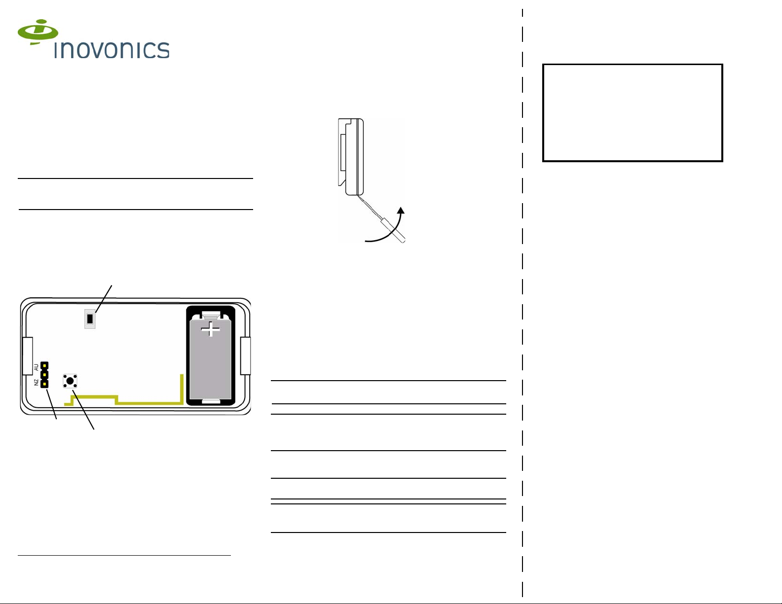
Lever Open
the Housing
EN1235DF Fixed Location Alarm
Transmitter
Installation Instructions
1 Overview
The Inovonics EN1235DF double button fixed location alarm
transmitter and EN1235SF single button fixed location alarm
transmitter feature a rugged design and housing and wall tamper
protection. The EN1235DF and EN1235SF are designed for fixed
position signaling.
Note: For UL installations, refer to the EN4216MR Installation and
Operation Manual, the EN4232MR Installation and Operation
Manual, or the EN7285 Installation Instructions.
1.1 Inovonics Wireless Contact Information
If you have any problems with this procedure, contact Inovonics
Wireless technical services:
• E-mail: support@inovonics.com
• Phone: (800) 782-2709
1.2 Transmitter Components
Figure 1 Transmitter components
A Reset button B Frequency band selection pins
C Tamper switch
1.3 What’s In The Carton
Individually-packaged products include the following it ems:
• One fixed location alarm transmitter
• One housing screws
• Two mounting screws
• Two selection jumpers
• One 3.0V lithium battery
2 Installation and Startup
2.1 Installation Notes
• These products are designed to be maintained by professional
security technicians.
• Products are intended for indoor use.
• Manually test all products weekly.
2.2 Install the Battery
1. Insert a small screwdriver into the notch on the bottom of the
transmitter, press the housing release tab, and, without twisting,
lever the housing apart..
Figure 2 Open the Housing
2. Install the battery.
3. Press the reset button to initialize the transmitter.
2.3 Select the Frequency Band
EchoStream products are able to use a range of radio frequencies, and must
be configured for your geographic area. This product ships with a default
frequency range of 902-928 MHz for use in North America. If you are using
the product in North America, skip to step 6. If you are using the product in
Australia or New Zealand, you will need to configure the transmitter.
To configure the transmitter:
4. Place a selection jumper on the appropriate frequency band
selection pins.
• Place the jumper on the top two pins, marked AU, to set the
frequency range to 915-928 MHz for Australia.
• Place the jumper on the bottom two pins, marked NZ, to set
the frequency range to 921-928 MHz for New Zealand.
Note: Only devices set for use in North America are configured for
UL installations.
5. Press the reset button to complete configuration.
Caution: When pressing the reset button, make sure you don’t also
touch the frequency band selection pins. Touching the frequency
band selection pins while pressing the Reset button can
inadvertently set the transmitter to the wrong frequency band.
2.4 Mount the Transmitter
To operate correctly, the transmitter must be mounted.
Caution: The transmitter must be mounted to operate correctly. If
not mounted, the transmitter will remain in a tamper state.
Caution: For UL installations, mount the EN1235DF/SF in a
concealed area, where its operation cannot be viewed from a public
space.
Printing Instructions
1. Print duplex
2. Align and orient back page to match front
page.
3. Cut on dashed line
4. Fold cutsheet in half along the 8.5" axis.
1/20/14 05834D © Inovonics, 2014 - www.inovonics.com

To mount the transmitter:
6. Use the included hardware to mount the back plate of the
transmitter housing to the mounting surface.
7. Hook the bottom of the transmitter into the back plate, then clip
the top into place.
Caution: The tamper spring must make contact with the mounting
surface through the slot in the back plate. Make sure to first hook
the bottom of the transmitter into the back plate and then clip the top
into place to ensure the tamper spring makes contact.
2.5 Register the Transmitter
The transmitter must be registered and supervised. When
supervised, the transmitter will send check-in message to the
receiver or gateway as follows:
• EN1235SF/EN1235DF: every three minutes.
• EN1235SF-15: every 15 minutes.
Each transmitter has a unique factory-programmed identification
number. Refer to the receiver’s installation instructions for details on
registering a transmitter.
8. When prompted by the receiver to reset transmitter, press the
reset button.
9. Replace the cover.
Caution: The transmitter should be tested after registration to
ensure operation. To test the transmitter, activate each of the
conditions and ensure an appropriate response.
2.6 Operate the Transmitter
To activate single button transmitters, press the button for at least
one second. To activate double button transmitters, press both
buttons simultaneously . Alarm signals are transmitted multiple times
and are indicated by the blinking transmission LED. When the
buttons are released, the transmitter sends an alarm restoral
signal.To test a transmitter, activate the alarm by pressing the
button(s).
3 Specifications
Typical battery life: 3-5 years
Battery type (BAT608): Panasonic CR2, Sanyo CR2
Operating environment: 0 to 60°C (32 to 140°F), 90% relative
humidity, noncondensing
Power requirement: 3 VDC, 60 mA
Note: Specifications and data are subject to change without notice.
EN1235DF/EN1235SF UL listings: UL 365, UL 636, UL 1076, UL
1610.
Compatible receiver: EN4216MR, EN4232MR, EN7285
4 Television and Radio Interference
This equipment has been tested and found to comply with the limits
for a Class B digital device, pursuant to Part 15 of the FCC Rules.
These limits are designed to provide reasonable protection against
harmful interference in a residential installation. This equipment
generates, uses and can radiate radio frequency energy and, if not
installed and used in accordance with the instructions, may cause
harmful interference to radio communications. However, there is no
guarantee that interference will not occur in a particular installation.
If this equipment does cause harmful interference to radio or
television reception, which can be determined by turning the
equipment off and on, the user is encouraged to try to correct the
interference by one or more of the following measures:
• Reorient or relocate the receiving antenna.
• Increase the separation between the equipment and receiver.
• Connect the equipment into an outlet on a circuit different from
that to which the receiver is connected.
• Consult the dealer or an experienced radio/TV technician for
help.
5 FCC Part 15 and Industry Canada
Compliance
This device complies with part 15 of the FCC Rules and Industry
Canada license-exempt RSS standard(s). Operation is subject to
the following two conditions: (1) this device may not cause
interference, and (2) this device must accept any interference,
including interference that may cause undesired operation of the
device.
Le présent appareil est conforme aux CNR d'Industrie Canada
applicables aux appareils radio exempts de licence. L'exploitation
est autorisée aux deux conditions suivantes : (1) l'appareil ne doit
pas produire de brouillage, et (2) l'utilisateur de l'appareil doit
accepter tout brouillage radioélectrique subi, même si le brouillage
est susceptible d'en compromettre le fonctionnement.
6 Warranty/Disclaimer
Caution: Changes or modifications not expressly approved by the
party responsible for compliance could void the user's authority to
operate the equipment.
Inovonics Wireless Corporation ("Inovonics") warrants its products
("Product" or "Products") to conform to its own specifications and to
be free of defects in materials and workmanship under normal use
for a period of thirty-six (36) months from the date of manufacture.
Within the warranty period, Inovonics will repair or replace, at its
option, all or any part of the warranted Product. Inovonics will not be
responsible for dismantling and/or reinstallation charges. To
exercise the warranty, the User ("User", "Installer" or "Consumer")
must work directly through their authorized distributor who will be
given a Return Material Authorization ("RMA") number by
Inovonics. Details of shipment will be arranged directly through the
authorized distributor.
This warranty is void in cases of improper installation, misuse,
failure to follow installation and operating instructions, alteration,
accident or tampering, and repair by anyone other than Inovonics.
This warranty is exclusive and expressly in lieu of all other
warranties, obligations or liabilities, whether written, oral, express,
or implied. There is no warranty by Inovonics that Inovonics product
will be merchantable or fit for any particular purpose, nor is there
any other warranty, expressed or implied, except as such is
expressly set forth herein. In no event shall Inovonics be liable for
an incidental, consequential, indirect, special, or exemplary
damages, including but not limited to loss of profit, revenue, or
contract, loss of use, cost of down time, or interruption of business,
nor any claim made by distributor's customers or any other person
or entity.
This warranty will not be modified or extended. Inovonics does not
authorize any person to act on its behalf to modify or extend this
warranty.
This warranty will apply only to Inovonics Products. Inovonics will
not be liable for any direct, incidental, or consequential damage or
loss whatsoever, caused by the malfunction of Product due to
products, accessories, or attachments of other manufacturers,
including batteries, used in conjunction with Inovonics Products.
Note: E-mail support@inovonics.com for a copy of the CE
Declaration of Conformity.
1/20/14 05834D © Inovonics, 2014 - www.inovonics.com
 Loading...