

EN1223S/EN1223S-60 EchoStream® Single-
C
A
B
A
B
C
Button Water-Resistant Pendant Transmitter
Installation and Operation Manual
1 Overview
The Inovonics single-button water-resistant pendant transmitter is our smallest,
lightest, and most versatile pendant.
Note: For UL 2560 installations, refer to the EN6080 Area Control Gateway
Installation Instructions.
1.1 Inovonics Wireless Contact Information
If you have any problems with this procedure, contact Inovonics Wireless technical
services:
• E-mail: support@inovonics.com
• Phone: 1.800.782.2709, option 2
1.2 Maximum Number of Repeaters for a UL 2560
Installation
To achieve the 99.99% alarm message reliability required for UL 2560 compliance,
system installations must operate within the following limits for end device and
repeater counts.
End Devices Maximum
150 397
250 386
350 375
500 360
1000 313
2000 238
3000 184
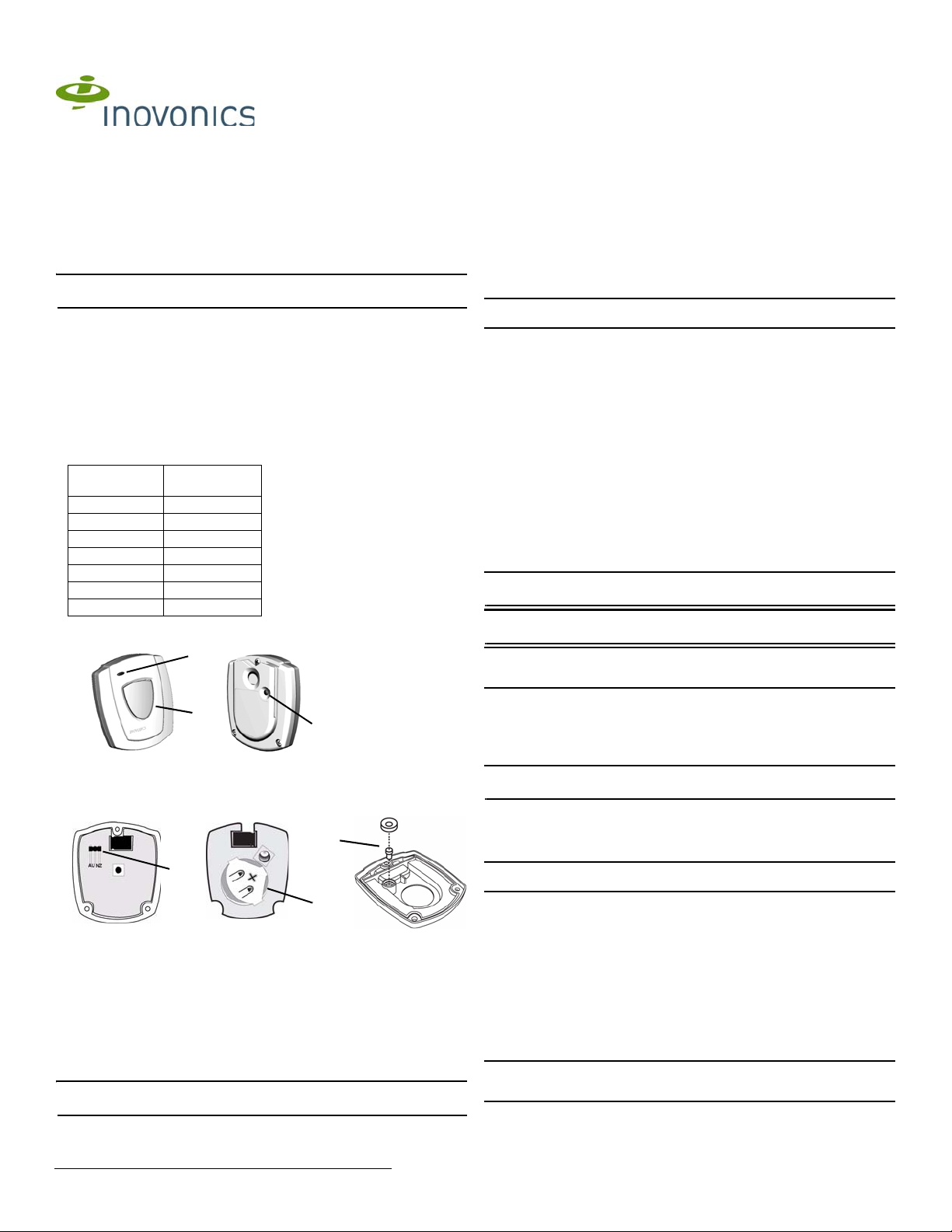
1.3 Transmitter External Components
Repeaters
2 Installation and Startup
2.1 Installation Notes
• These products are designed to be maintained by professional security
technicians
• Products are intended for indoor use
• All products should be manually tested weekly (see “Test the Transmitter” on
page 2)
2.2 Battery Installation
1. Remove the rear housing cover to expose the side of the board that holds the
battery.
Caution: Carefully separate the rear hou sing cover, ensuring the reset button pl unger
assembly does not fall out of the housing (Figure 2).
2. Slide the battery under the battery holder, ensuring t hat it is f ully inse rte d an d that
the positive terminal (+) faces up (Figure 2).
2.3 Select the Frequency Band
EchoStream products are able to use a range of radio frequencies, and must be
configured for your geographic area. This product ships with a de fault frequency range
of 902-928 MHz for use in North America. If you are using the product in North
America, skip to step 6; if you are using the product in Australia or New Zealand, you
will need to configure the transmitter.
To configure the transmitter:
3. Turn the board over to access the side with the frequency band selection pins
(Figure 2).
4. Place the frequency band selection jumper on the appropriate frequency band
selection pins.
• Place the jumper on the left two pins, marked AU, to set the frequency range to
915-928 MHz for Australia.
• Place the jumper on the right two pins, mar ked NZ, to set t he frequency range to
921-928 MHz for New Zealand.
5. Seat the board in the housing with the battery side facing the rear housing cover.
6. Replace the front housing cover.
7. Insert the three housing screws, tightening them to 1.25 inch-pounds torque.
Note: If you do not have a torque driver, tighten to a snug fit, being careful not to
overtighten.
Note: Tighten the housing screws evenly to help ensure a good seal and maintain
water-resistance.
Figure 1 Transmitter external components
A Transmit LED B Activation button C Reset button
1.4 Transmitter Internal Components
Figure 2 Transmitter internal components
A Frequency band selection pins B Battery C Reset button plunger
assembly
1.5 What’s In The Carton
Individually-packaged products include the following it ems:
• One EchoStream single-button water-resistant pendant transmitter
• One breakaway neck cord
• One beltclip attachment
• Three housing screws
• One frequency band selection jumper
• One CR2450 coin cell battery
Note: Bulk-packaged products are shi pped with mult iples of th e ab ove items, with th e
exception of batteries.
Caution: Over-tightening the housing screws can result in microcracks in the plastic,
gaps in the gasket material, and/or stripping of the bushing. Any of these condit ions
can compromise the water-resistance of the device.
2.4 Register the Transmitter
The transmitter must be registered and supervised. When supervised, the transmitter
will send check-in message to the receiver or gateway as follows:
• EN1223S: every three minutes.
• EN1223S-60: every 60 minutes.
Note: In UL 2560 installations, transmitters send a check-in message every 60
minutes.
Each transmitter has a unique factory-programmed identif ication nu mber. Refer to the
receiver or gateway's installation instructions for details on registering and setting up
supervision.
8. When prompted by the receiver or gateway to reset transmitter, press the reset
button (Figure 1).
Caution: The transmitter should be tested after registration to ensure operation. See
“Test the Transmitter” on page 2.
3 Operate the Transmitter
To send an alarm, press the activation button for at least one second. Alarm signals
are transmitted multiple times and are indicated by the blinking transmission LED.
When the button is released, the transmitter sends an alarm resto ral signal as
indicated by another short series of blinking transmission LED lights.
3.1 Wear the Transmitter
The pendant transmitter can be worn in three ways:
• Around the neck with neck chain attachment (included)
• On a belt with the beltclip attachment (included)
• On the arm with optional wristband accessory (ACC623S or ACC623L, sold
separately)
Caution: The neck chain included with the pendant transmitter is designed with a
breakaway feature for user safety. Substitution of a stronger cord or chain may result
in injury to the wearer.
1/23/14 05582F © Inovonics, 2014 - www.inovonics.com

3.2 Water Exposure
UL has evaluated the single-button pendant transmitter to meet the water spray test
required under UL 2560, section 38.1. Because the single-button pendant transmitter
was not designed for submersion in water, it was not subjected to submersion tests
under that standard.
All EchoStream water-resi stant pendants also meet IP54 certificatio n standards for
dust and water ingress protection, ensuring that:
• Ingress of dust particles does not interfere with the satisfactory opera tion of the
device
• There is no harmful effect to the device caused by:
- Vertically dripping water (when device is ti lted up to 15° from normal position)
- Spraying water (falling at angles up to 60° from vertical)
- Splashing water (from any direction)
Note: IP54 certification was performe d by an independent labo ratory not af filiated with
UL.
End User Recommendations
The pendant transmitter is water-resistant, but not waterproof. The product is not
designed for submersion in water . As such, we offe r the following recommenda tions to
the end user:
Usage Situation OK to Use? Cautions
Shower Yes Do not spray water directly on the
Bath Ye s Do not submerge the device
Rain Yes Avoid extended exposure; wear the
Water Exercise No Do not use the device during these
device at distances of less than 12
inches; avoid spraying water at high
pressure
device under a sleeve, shirt, or
jacket
activities
3.3 Battery Replacement
Replacement batteries can be purchased from Inovonics using the following part
numbers
• BAT609 for a single battery
• BAT609-25 for a 25-count bulk pack
To replace the batteries:
1. Remove the three housing screws on the back of the transmitter.
2. Remove the rear cover to expose the side of the board which holds the battery.
Caution: Carefully separate the rear housing cover, ensuring the reset button plunger
assembly does not fall out of the housing (Figure 2).
3. Remove the depleted battery.
4. Slide the new battery under the battery holder, ensuring that it is fully inserted and
that the positive terminal (+) faces up (Figure 2).
5. Replace the rear housing cover.
6. Replace the three housing screws, tightening them to 1.25 inch-pounds torque.
7. Once the unit has been sealed, press the reset button located on the rear hou sing
to complete the configuration (Figure 1).
Note: If you do not have a torque driver, tighten to a snug fit, being careful not to strip
the housing.
Note: Tighten the housing screws evenly to help ensure a good seal and maintain
water-resistance.
Caution: Over-tightening the housing screws can result in microcracks in the plastic,
gaps in the gasket material, and/or stripping of the bushing. Any of these conditions
can compromise the water-resistance of the device.
4 Test the Transmitter
The transmitter should be tested weekly and after registration to ensure operation.
To test the transmitter:
1. Press the activation button for at least one second and ensure the transmit LED
lights and the alarm is received by the receiver or gateway.
2. Press the reset button and ensure the transmit LED lights.
5 Specifications
Dimensions: 5.6 x 4.8 x 1.8 cm (2.2 x 1.9 0.72”)
Operating temperature: 0 to 60°C (32 to 140°F)
Operating environment: Water-resistant, non-submersible
Typical battery life: 1-2 years
Battery type: Panasonic CR2450
Power requirement: 3 VDC, 60 mA
UL certification for EN1223S-60: UL 2560 (see conditions below)
Note: For UL 2560 installations, Inovonics repeaters must have 20 minute check-in
times. Inovonics transmitters must have a minimum of 60 minute check-in times.
Note: In a UL 2560 installation, the EN1223S-60 single-button water-resistant
pendant transmitter may be used with completed emergency call systems for assisted
living and independent living facilities
For UL 2560 certified system installations, the following Inovonics EchoStream
devices are approved for installation within maximum system configuration limits
defined in section 1.2 of this document:
• EN6080 area control gateway
• EN5040-20T high power repeater
• End devices (transmitters) with a minimum 60-minute check-in interval, as
follows:
- Fundamental devices which are subject to UL2560 certification (pendant
transmitters and OEM products using the Inovonics RF module)
- Supplemental devices which are not subject to UL25 60 system certificat ion but
which may be used within a UL2560 certified system (e.g. universal
transmitters and activity sensors)
Note: Users that have achieved certification and will install UL 2560 certified systems
are responsible for labeling all fundamental devices with the UL 2560 system
certification mark.
Compatible receiver for UL 2560 installations with the EN1223S-60: EN6080
Compatible repeater for UL 2560 installations with the EN1223S-60: EN5040-20T
Note: Specifications and data are subject to change without notice.
6 Television and Radio Interference
This equipment has been tested and found to comply with the limits for a Class B
digital device, pursuant to Part 15 of the FCC Rules. These limits are designed to
provide reasonable protection against harmful interference in a residential installat ion.
This equipment generates, uses and can radiate radio frequency energy and, if not
installed and used in accordance with the instructions, may cause harmful
interference to radio communications. However, there is no guarantee that
interference will not occur in a particular installation. If this equipment does ca use
harmful interference to radio or television reception, which can be determined by
turning the equipment off and on, the user is encouraged to try to correct the
interference by one or more of the following measures:
• Reorient or relocate the receiving antenna.
• Increase the separation between the equipment and receiver.
• Connect the equipment into an outlet on a circuit different fro m that t o which the
receiver is connected.
• Consult the dealer or an experienced radio/TV technician for help.
7 FCC Part 15 and Industry Canada Compliance
This device complies with part 15 of the FCC Rules and Industry Canada licenseexempt RSS standard(s). Operation is subject to the following two conditions: (1) this
device may not cause interference, and (2) this device must accept any interference,
including interference that may cause undesired operation of the device. Changes or
modifications not expressly approved by the party responsible for compliance could
void the user's authority to operate the equipment.
Le présent appareil est conforme aux CNR d'Industrie Canada applicables aux
appareils radio exempts de lice n ce. L'exploitation est autori s é e a ux deu x co n di tions
suivantes : (1) l'appareil ne doit pas produire de brouillage, et (2) l'utilisateur de
l'appareil doit accepter tout brouillage radioélectrique subi, même si le brouillage est
susceptible d'en compromettre le fonctionnement.
8 US Patent Numbers
• 7,154,866
• 7,554,932
• 7,746,804
9 Warranty and Disclaimer
Inovonics Wireless Corporation ("Inovonics") warrants its products ("Product" or
"Products") to conform to its own specifications and to be free of defects in materials
and workmanship under normal use for a period of thirty-six (36) months from the date
of manufacture. Within the warranty period, Inovonics will repair or replace, at its
option, all or any part of the warranted Product. Inovonics will not be responsible for
dismantling and/or reinstallation charges. To exercise the warranty, the User ("User",
"Installer" or "Consumer") must work directly through their authorized distributor who
will be given a Return Material Authorization ("RMA") number by Inovonics. Details of
shipment will be arranged directly through the authorized distributor.
This warranty is void in cases of improper installation, misuse, failure to follow
installation and operating instructions, alteration, accident or tampering, and repair by
anyone other than Inovonics.
This warranty is exclusive and expressly in lieu of all other warranties, obligations or
liabilities, whether written, oral, express, or implied. There is no warranty by Inovonics
that Inovonics product will be merchantable or fit for any particular purpose, nor is
there any other warranty, expressed or implied, except as such is expressly set forth
herein. In no event shall Inovonics be liable for an incidental, consequential, indirect,
special, or exemplary damages, including but not limited to loss of profit, revenue, or
contract, loss of use, cost of down time, or interruption of business, nor any claim
made by distributor's customers or any other person or entity.
This warranty will not be modified or extended. Inovonics does not authorize any
person to act on its behalf to modify or extend this warranty.
This warranty will apply only to Inovonics Products. Inovonics will not be liable for any
direct, incidental, or consequential damage or loss whatsoever, caused by the
malfunction of Product due to products, accessories, or attachments of other
manufacturers, including batteries, used in conjunction with Inovonics Products.
1/23/14 05582F © Inovonics, 2014 - www.inovonics.com 2
 Loading...