

EN1215WEOL EchoStream® Universal
A
B
A
B
C
D
E
E
F
G
H
Transmitter with Wall Tamper
Installation Instructions
1 Overview
The Inovonics EN1215WEOL wide gap universal transmitter with an
included wall tamper switch has a built-in magnetic reed switch on the
side, with a magnet that supports a 5/8" inch gap. The magnetic reed
switch can be used with both ferrous and non-ferrous material. A 2.2K
ohm end of line resistor is included with the EN1215WEOL, and is
required for operation.
The EN1215WEOL includes a back tamper switch. The tamper condition
must be defined within the control panel as a trouble condion when the
system is disarmed, and as an alarm condition when the system is armed.
Note: For UL installations, refer to the EN4216MR Installation and
Operation Manual, the EN4232MR Installation and Operation Manual, or
the EN7285 Installation Instructions . The swi tch contact must also be
located in the same room as the EN1215WEOL, and the EN1215WEOL
must be installed in accordance with UL 681 and ULc S302.
Note: The cable length from the switch contact must not to exceed 10
feet.
Caution: The EN1215WEOL contains both a wired input and an input
activated by a reed switch and magnet. The reed switch and magnet
MUST be used unless the application (control panel) specifically supports
both inputs as separate devices. Use of the wired input is optional.
1.1 Inovonics Wireless Contact Information
If you have any problems with this procedure, contact Inovonics technical
services:
• E-mail: support@inovonics.com
• Phone: (800) 782-2709
1.2 EN1215WEOL External Components
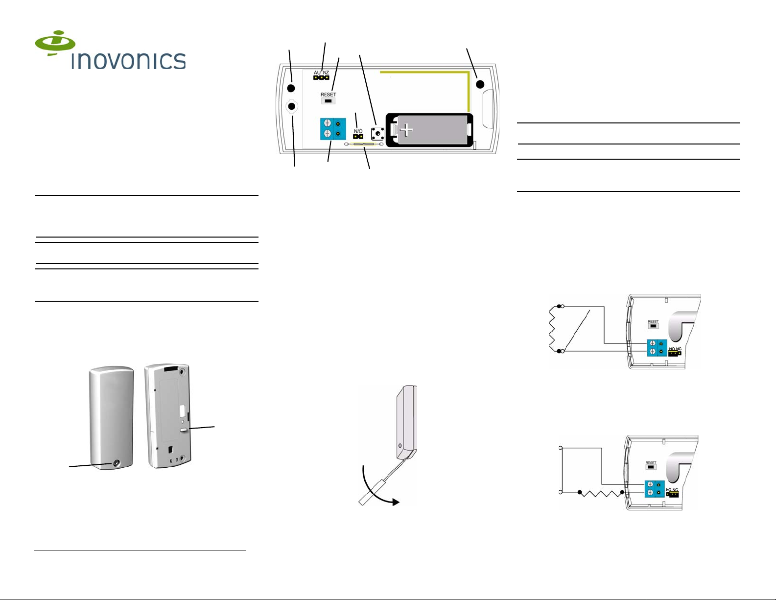
1.3 EN1215WEOL Internal Components
Figure 2 EN1215WEOL internal components
A Housing tamper button B N/O - N/C jumper
C Input terminal D Re se t bu tt o n
E Wall-mount screw holes F Housing closure screw hole
G Reed switch H Frequency band selection pins
1.4 What’s In The Carton
• Wall mount screws
• Wall mount anchors
• Selection jumpers
• 3.0V lithium battery
• Housing closure screw
• Magnet
• 2.2K ohm end of line resistor
2 Installation and Startup
2.1 Installation Notes
• These products are designed to be installed and maintained by
professional security technicians.
• Products are intended for indoor use.
• Manually test all products weekly.
2.2 Initial Setup
Battery Installation
1. Insert a small screwdriver to depress the housing release tab on the
bottom of the transmitter; pry the housing apart.
Select the Frequency Band
EchoStream products are able to use a range of radio frequencies, and
must be configured for your geographic area. This product ships with a
default frequency range of 902-928 MHz for use in North America. If you
are using the product in North America, skip to ste p 7; if you are using t he
product in Australia or New Zealand, you will need to configure the
transmitter.
5. Place a selection jumper on the appropriate frequency band selection
pins.
• Place the jumper on the right two pins, marked NZ, to set the
frequency range to 921-928 MHz for New Zealand.
• Place the jumper on the left two pins, marked AU, to set the
frequency range to 915-928 MHz for Australia.
Note: Only devices set for use in North America are configured for UL
installations.
6. Press the Reset button to complete configuration.
Caution: When pressing the Reset button, make sure you don’t also
touch the frequency band selection pins. Touching the frequency band
selection pins while pressing the Reset button can inadvertently set the
EN1215WEOL to the wrong frequency band.
Select Input Type and Wire Resistor
The N/O-N/C selection pins allow the choice of a normally open or
normally closed state for the contact circuit wired to the input terminal.
The transmitter is shipped set for normally open, with a selection jumper
on the N/O selections pins.
Set for normally open operation:
7. Place a selection jumper on the selection pins to select normally
open.
8. Use 22 AWG wire to wire the 2.2K ohm resistor in p arallel with t he N/0
contact per Figure 4. The distance from the external contact to the
EN1215WEOL must not exceed 10 feet (3 meters).
9. Press the Reset button to complete configuration.
Figure 4 Wired for N/O operation
Set for normally closed operation:
10. Remove the selection jumper from the selection pins.
11. Use 22 AWG wire to wire the 2 .2K ohm resistor in series with the N/C
contact per Figure 5. The distance from the external contact to the
EN1215WEOL must not exceed 10 feet (3 meters).
12. Press the Reset button.
Figure 1 EN1215WEOL external components
A Housing closure screw hole B Wall tamper switch
6/7/12 05043G © Inovonics, 2012 - www.inovonics.com
Figure 3 Open the EN1215WEOL Housing
2. Install the new battery.
3. Press the Reset button to initialize the transmitter.
4. Test the tran smitter and ensure appropriate response.
Figure 5 Wired for N/C operation

Register the EN1215WEOL
Wall Tamper
Switch
Transmitters must be registered with the system in order to be monitored
and supervised. When supervised, the transmitter will send a check-in
message to the receiver every three minutes. Each transmitter has a
unique factory-programmed identification number.
Refer to the system receiver’s documentation for details on regist ering the
transmitter.
13. When prompted by the receiver to reset transmitter, press the Reset
button (Figure 2).
14. Replace the cover.
15. Test the transmitter and ensure appropriate response.
Mount the EN1215WEOL
16. Choose a mounting location which will allow the magnet to be located
parallel to the transmitter such that there is no more than a 5/8” gap
between it and the internal contact magnetic reed switch (Figure 2).
17. Route the external wiring through the wall, as shown in Figure 6.
18. Mount the transmitter to the wall using the the wall-mount screw holes
(Figure 2), ensuring the housing is flush against the wall and the wall
tamper switch is firmly depressed.
Figure 6 Mount the Transmitter to the Wall
19. Close the housing.
20. Secure the housing through the enclosed housing screw hole (Figure
2). Accessing this screw on an active transmitter requires opening the
housing and removing the battery, causing a tamper condition.
Mount the Magnet
21. Mount the magnet so that it is parallel to the transmitter with no more
than a 5/8” inch gap between it and the int ernal cont act magneti c reed
switch.
3 Operate the Transmitter
3.1 Battery Replacement
1. Insert a small screwdriver to depress the housing release tab on the
bottom of the transmitter; pry the housing apart.
3. Install the new battery.
4. Press the Reset button to initialize the transmitter.
5. Test the tran smitter and ensure appropriate response.
4 Specifications
Note: A 2.2K ohm resistor is required to operate the EN1215WEOL.
Dimensions: 3.5x1.7x0.9" (89x43x23 mm)
Weight: 3 oz (85g)
External contacts: N/O or N/C
Distance, external contact to EN1215WEOL: 10 feet (3 meters) maximum
Distance, magnet to internal contact magnetic ree d switch: 5/8”
Power requirement: 3VDC, 60 mA
Typical battery life: 3-5 years
Battery type (BA T6 04): Panasonic CR123A
Operating environment: 0 to 60°C (32 to 140°F), 90% relative humidity,
noncondensing; 0 to 49°C (32 to 120°F) for UL installations
Note: Specifications and data are subje ct to change without notice.
UL listings: UL 365, UL 634, ULC/ORD-C634-86, UL 1023, ULC/ORD-
C1023-74, UL 1076, UL 1610.
Compatible receiver: EN4216MR, EN4232MR, EN7285
5 Television and Radio Interference
This equipment has been tested and found to comply with the limits for a
Class B digital device, pursuant to Part 15 of the FCC Rules. These limits
are designed to provide reasonable protection against harmful
interference in a residential installation. This equipment generates, uses
and can radiate radio frequency energy and, if not installed and used in
accordance with the instructions, may cause harmful interference to radio
communications. However, there is no guara ntee tha t interference will not
occur in a particular installation. If this equipment does cause harmful
interference to radio or television reception, which can be determined by
turning the equipment off and on, the user is encouraged to try to correct
the interference by one or more of the following measures:
• Reorient or relocate the receiving antenna.
• Increase the separation between the equipment and receiver.
• Connect the equipment into an outlet on a circuit different from that
to which the receiver is connected.
• Consult the dealer or an experienced radio/TV technician for help.
6 FCC Part 15 and Industry Canada Compliance
This device complies with part 15 of the FCC Rules and Industry Canada
license-exempt RSS standard(s). Operation is subject to the f ollowing t wo
conditions: (1) this device may not cause interference, and (2) this device
must accept any interference, including interference that may cause
undesired operation of the device.
Le présent appareil est conforme aux CNR d'Industri e Canada applicables
aux appareils radio exempts de licence. L'exploitation est autorisée aux
deux conditions suivantes : (1) l'appareil ne doit pas produire de
brouillage, et (2) l'utilisateur de l'appareil doit accepter tout brouillage
radioélectrique subi, même si le brouillage est susceptible d'en
compromettre le fonctionnement.
8 Warranty/Disclaimer
Caution: Changes or modifications not expressly approved by the party
responsible for compliance could void the user's authority to operate the
equipment.
Inovonics Wireless Corporation ("Inovonics") warrants its products
("Product" or "Products") to conform to its own specifications and to be
free of defects in materials and workmanship under normal use for a
period of thirty-six (36) months from the date of manufacture. Within the
warranty period, Inovonics will repair or replace, at its option, all or any
part of the warranted Product. Inovonics will not be responsible for
dismantling and/or reinstallation charges. To exercise the warranty, the
User ("User", "Installer" or "Consumer") must work directly through their
authorized distributor who will be given a Return Material Authorization
("RMA") number by Inovonics. Details of shipment will be arranged
directly through the authorized distributor.
This warranty is void in cases of improper installation, misuse, failure to
follow installation and operating instructions, alteration, accident or
tampering, and repair by anyone other than Inovonics.
This warranty is exclusive and expressly in lieu of all other warranties,
obligations or liabilities, whether written, oral, express, or implied. There is
no warranty by Inovonics that Inovonics product will be merchantable or fit
for any particular purpose, nor is there any other warranty, expressed or
implied, except as such is expressly set forth herein. In no event shall
Inovonics be liable for an incidental, consequential, indirect, special, or
exemplary damages, including but not limited to loss of prof it, revenue, or
contract, loss of use, cost of down time, or interruption of business, nor
any claim made by distributor's customers or any other person or entity.
This warranty will not be modified or extended. Inovonics does not
authorize any person to act on its behalf to modify or extend t his warranty.
This warranty will apply only to Inovonics Products. Inovonics will not be
liable for any direct, incidental, or consequential damage or loss
whatsoever, caused by the malfunction of Product due to products,
accessories, or attachments of other manufacturers, including batteries,
used in conjunction with Inovonics Products.
Figure 7 Open the EN1215WEOL Housing
2. Remove the old battery.
6/7/12 05043G © Inovonics, 2012 - www.inovonics.com
7 US Patent Numbers
• 7,154,866
• 7,554,932
• 7,746,804
 Loading...