

Inovonics EN1210W-60 User Manual
EN1210W/EN1210W-60 EchoStream® Door/
A
B
C
F
E
D
G
Mount the magnet
per the mounting
directions on the
inside of the bracket
Mounting
holes
Window Transmitter with Reed Switch
1 Overview
The EN1210W and EN1210W-60 are universal transmitters with one
internal contact magnetic reed switch. Inovonics mult-function add-o n
receivers will support both inputs as separate devices.
Note: The transmitter contains both a wired input and an input activated
by a reed switch and magnet. The reed switch and magnet must be used
unless the application (control panel) specifically supports both inputs as
separate devices. Use of the wired input is o ptional.
Note: For UL 2560 installations, refer to the EN6080 Area Control
Gateway Installation Instructions.
1.1 Maximum Number of Repeaters for a UL2560 Installation
To achieve the 99.99% alarm message reliability required for UL2560
compliance, system installations must operate within the following limits
for end device and repeater counts.
End Devices Maximum
150 397
250 386
350 375
500 360
1000 313
2000 238
3000 184
1.2 Inovonics Wireless Contact Information
If you have any problems with this procedure, contact Inovonics Wireless
technical services:
• E-mail: support@inovonics.com.
• Phone: (800) 782-2709.
Repeaters
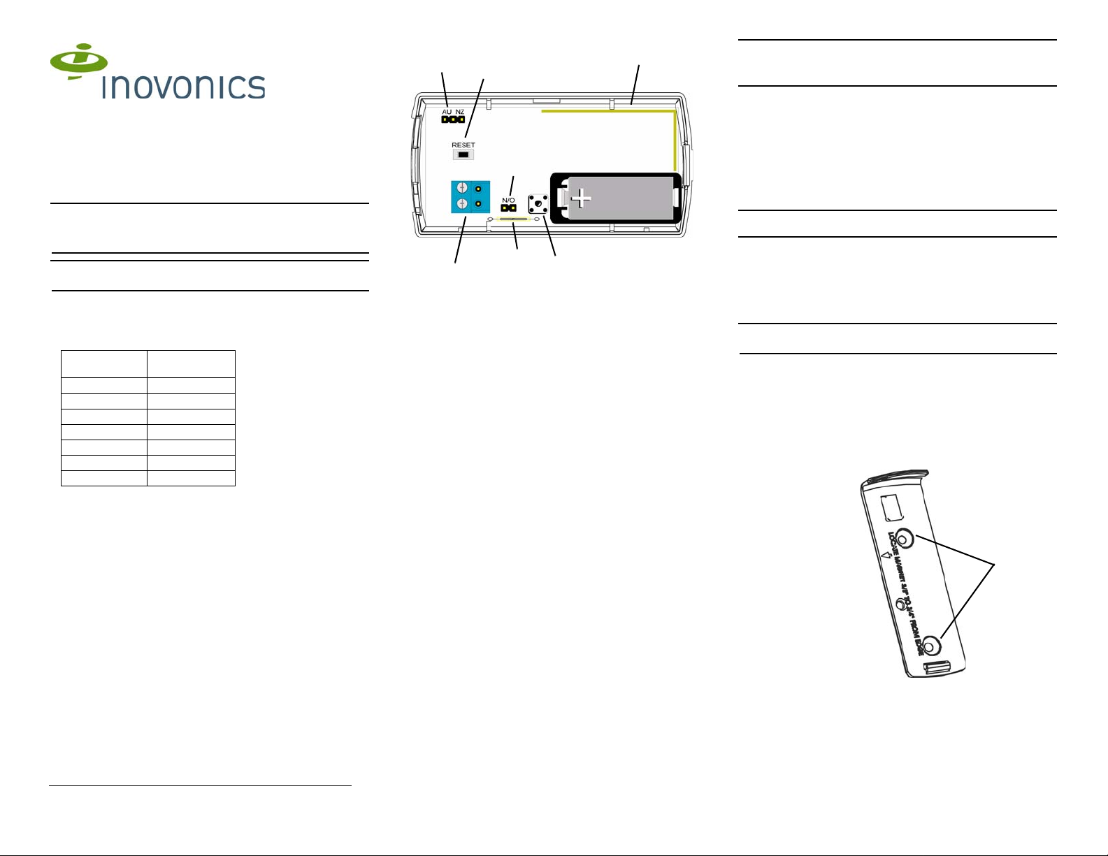
1.3 Internal Components
Figure 1 Components
A Frequency band selection
pins
C Antenna D Input terminal
E N/O - N/C selection pins F Tamper but ton and spring
G Reed switch
1.4 What’s In The Carton
• Three wall mount screws.
• Three wall mount anchors.
• Two selection jumpers.
• One 3.0V lithium battery.
• One magnet.
B Reset button
2 Installation and Startup
2.1 Installation Notes
• These products are designed to be installed and maintained by
professional security technicians.
• Products are intended for indoor use.
• Manually test all products weekly.
2.2 Install the Battery
1. Pry the top lip of the mounting bracket up, and lift the bracket of f of the
transmitter.
2. Use your thumb to depress the housing release tab on the bottom of
the transmitter; separate the housing.
3. Install the new battery.
4. Press the reset button to initialize the transmitter.
2.3 Select the Frequency Band
EchoStream products are able to use a range of radio frequencies, and
must be configured for your geographic area. This product ships with a
default frequency range of 902-928 MHz for use in North America. If you
are using the product in North America, skip to section 2.4, “Select Input
Type”; if you are using the product in Australia or New Zealand, you will
need to configure the transmitter.
5. Place a selection jumper on the appropriate frequency band selection
pins.
• Place the jumper on the right two pins, marked NZ, to set the
frequency range to 921-928 MHz for New Zealand.
• Place the jumper on the left two pins, marked AU, to set the
frequency range to 915-928 MHz for Australia.
6. Press the reset button to complete configuration.
Caution: When pressing the reset button, make sure you don’t also touch
the frequency band selection pins. Touching the frequency band selection
pins while pressing the reset button can inadvertently set th e transmitter to
the wrong frequency band.
2.4 Select Input Type
The N/O-N/C selection pins allow the choice of a normally open or
normally closed state for the contact ci rcuit wired to the input termi nal. The
transmitter is shipped set for normally open, with a selection jumper on the
N/O selections pins. If you are using the product in a normally open state,
skip to section 2.5, “Register the Transmit ter”; if you are using the pro duct
in a normally closed state, you will need to configure the transmitter:
7. Remove the selection jumper from the selection pins to select
normally closed.
8. Press the reset button to complete configuration.
Caution: If only the reed switch and magnet are to be used, normally
open should be selected.
2.5 Register the Transmitter
Transmitters must be registered with the system in orde r to be monitored
and supervised. The EN1210W sends a check-in message every thr ee
minutes; the EN1210W-60 sends a check-in message every 60 minutes.
Each transmitter has a unique factory-programmed identification number.
Refer to the receiver installation instructions for details on registering a
transmitter.
Note: For UL 2560 installations, transmitters must have a minimum
check-in time of 60 minutes.
9. When prompted by the receiver to reset transmitter, press the reset
button.
10. Replace the cover.
11. Test the transmitter by activating each of the conditions and ensuring
an appropriate response.
2.6 Mount the Transmitter
12. Mount the bracket on the wall with the screws provided, ensuring
room for the magnet where indicated by the mounting directions on
the inside of the bracket.
Figure 2 Mount the bracket
13. Mount the magnet where indicated by the mounting arrow on the
inside of the bracket,
14. Clip the transmitter onto the bracket. Hook the bott om catch fi rst, then
press the top into place.
15. As desired, use the third mounting screw to secure the housing
through the screw hole located beneath the battery.
5/21/14 04858I © Inovonics, 2014 - www.inovonics.com

Note: Accessing this screw on an active transmitter requires opening the
housing and removing the battery, causing a tamper condition.
16. Replace the housing lid.
3 Operate the Transmitter
The transmitter has one internal contact magnetic reed switch. The
magnet should be parallel with the reed switch. The maximum operating
gap between the magnet and the reed switch is 16mm (5/8”). The
transmitter can monitor internal and external contacts at the same time.
4 US Patent Numbers
• 7,154,866.
• 7,554,932.
• 7,746,804.
• Other patents pending.
5 Specifications
External contacts: N/O or N/C.
Distance, external contact to transmitter: 3 meters (10 feet) maximum.
Typical battery life: 3-5 years.
Battery type (BAT 604): Panasonic CR123A or equivalent.
Power requirement: 3VDC, 60 mA.
Operating environment: -20° to 60°C (-4° to 140°F), noncondensing.
Compatible receiver for UL 2560 installations with the EN1210W-60:
EN6080.
Compatible repeater for UL 2560 installations with the EN1210W-60:
EN5040-20T.
Note: The EN1210W-60 is a supplemental device that can be installed in
a UL 2560 certified system.Specifications and data are subject to change
without notice.
6 Television and Radio Interference
This equipment has been tested and found to comply with the limits for a
Class B digital device, pursuant to Part 15 of the FCC Rules. These limits
are designed to provide reasonable protection against harmful
interference in a residential installation. This equipment generates, uses
and can radiate radio frequency energy and, if not inst alled and used in
accordance with the instructions, may cause harmful interference to radio
communications. However, there is no guarant ee that interf erence will not
occur in a particular installation. If this equipment does cause harmful
interference to radio or television reception, which can be determined by
turning the equipment off and on, the user is encouraged to try to correct
the interference by one or more of the following measures:
• Reorient or relocate the receiving antenna.
• Increase the separation between the equipment and receiver.
• Connect the equipment into an outlet on a circuit different fro m that
to which the receiver is connected.
• Consult the dealer or an experienced radio/TV technician for help.
Note: Changes or modifications not expressly approved by the party
responsible for compliance could void the user's authority to operate the
equipment.
7 FCC Part 15 and Industry Canada Compliance
This device complies with part 15 of the FCC Rules and Industry Canada
license-exempt RSS standard(s). Operation i s subject to t he following t wo
conditions: (1) this device may not cause interference, and (2) this device
must accept any interference, including interference that may cause
undesired operation of the device. Changes or modifications no t expressly
approved by the party responsible for compliance could void the user's
authority to operate the equipment.
Le présent appareil est conforme aux CNR d'Ind ustrie Canada applicables
aux appareils radio exempts de licence. L'exploitation est autorisée aux
deux conditions suivantes : (1) l'appareil ne doit pas produire de
brouillage, et (2) l'utilisateur de l'appareil doit accepter tout brouillage
radioélectrique subi, même si le brouillage est susceptible d'en
compromettre le fonctionnement.
5/21/14 04858I © Inovonics, 2014 - www.inovonics.com
 Loading...