

EE4216MR EchoStream® Receiver
A
B
C
D
E
A
B
C
D
G
H
F
E
A
A
I
Installation and Operation Manual - 05395I
1 Overview
Inovonics EchoStream technology is designed to minimize dead spots in tran smission
areas using diversity reception and advanced signal processing. The EE4216MR
receiver allows you to add up to 16 transmitters and six outputs to any application.
The EE4216MR is compliant with:
• EN50131-1
• Security Grade 2
• Environmental Class II
1.1 Inovonics Wireless Contact Information
If you have any problems with this procedure, contact Inovonics Wireless technical
services:
• E-mail: support@inovonics.com
• Phone: (800) 782-2709; (303) 939-9336
1.2 EE4216MR Front Panel
Figure 1 Receiver front panel
A Up button B Down button C Back button D Enter button E LCD display
Up Button Scrolls the display up.
Down button: Scrolls the display down.
Back button: Returns display to the previous menu, or, when entering information in
the display, returns to the last character entered.
Enter button: Selects the currently displayed menu item. If in normal operating mode,
sets the unit to menu mode.
LCD Display: Shows status, event log and programming information.
Note: The EE4216MR LCD will only display information when an au thorized password
has been entered.
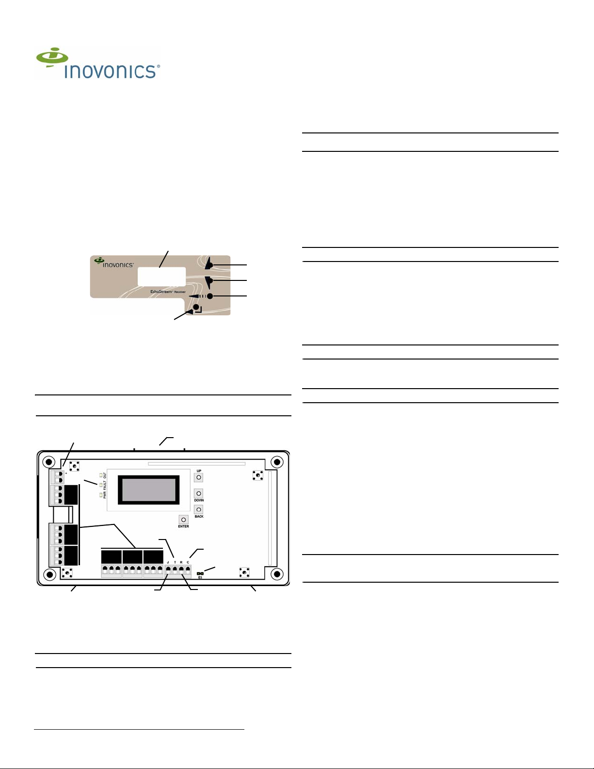
1.3 EE4216MR Internal Components
Figure 2 EE4216MR internal components
A Housing release tabs B Power connections C Operation LEDs
D Output terminals E Tamper output F Clear to set output
G Jam output H Reset input I EchoStream Select pins
1.4 EE4216MR LEDs
Note: The EE4216MR operation LEDs are only visible when the cover is removed.
Output LED: Lights when any output is active.
Fault LED: Lights when any transmitter is sending a fault condition.
Power LED: Lit when receiving power.
Decode LED: Flashes when any recognizable transmission is received. This LED is
only visible with the cover removed.
© Inovonics, 2011 - www.inovonics.com
2 Installation and Startup
2.1 Connect Power Cabling
Before beginning startup, you will need to connect power to the receiver. To connect
power to the receiver:
Caution: Graded application must use the cabling knockout on the back of the
housing.
1. Connect power cabling to the Vs and GND connections.
• Power source should be 11-14 VDC. Power supply must be unswitched,
uninterrupted, and regulated.
2.2 Enable EchoStream Select
To meet ETSI requirements, Inovonics has developed a new line of EE 868MHz-only
products. These new 868MHz-only products are compatible with older systems that
include EchoStream Select product s. If y ou are using any ES product s in your cu rrent
system, you will need to enable EchoStre am Select comp atibi lity on this new 868MHzonly product.
To enable/disable EchoStream Select compatibility:
1. To enable compatibility with ES products, place a selection jumper on the ES
selection pins.
Note: Selection jumpers are included in the EE4216MR hardware packet .
2. If no ES products are used in your system, remove the selection jumper from the
ES selection pins.
3. Reset the receiver or cycle power.
2.3 Enter Password
There are three levels of EE4216MR user. Only the level 2 author ized user and level 3
authorized installer are able to access the I
Level 2 authorized user access: A level 2 authorized user has the ability to view
system status indicators and enter system test mode in the I
A level 2 user does not have the ability to change receiver parameters or perform
receiver functions (signal strength, test, register points, etc.). For more information on
system test mode, see “System Test Mode” on page3.
Note: The default level 2 authorized user password is 3446.
Level 3 authorized installer access: A level 3 authorized installer has the ability to
access all I
receiver system status indicators as well as change receiver system parameters and
perform all receiver functions.
Note: The default level 3 authorized installer password is 1234.
During normal operation there is no visual indication of syst em statu s or activity on t he
front display of the EE4216MR receiver . Unless the level 2 aut horized user or the level
3 authorized installer enters a valid password, the LCD will remain completely blank.
To enter either the level 2 authorized user or the level 3 authorized inst aller password:
1. Press any button; P
2. Use the Up and Down buttons to scroll through the first numeral; press Enter to
3. Repeat step 2 for each numeral in the password.
4. When all numerals in the password have been entered, press Enter to submit the
2.4 Select Display Language
On initial startup you will need to select the display language . Once selected, the
language will be maintained unless changed using the C
the I
on page 3.
2.5 Navigate to the Install & Service Menu
There are three main menus: POINT STATUS, INSTALL & SERVICE and EVENT LOG. The
INSTALL & SERVICE menu is used to program outputs, select language, change
password, view the signal strength, delete points, register transmitters, and setup
points for any of the programmed points.
Note: If changing programming for a point that already has a transmitter registered to
it, there is no need to re-register the transmitter. Changes to point programming are
automatically assigned to the transmitter registered to that point.
To access the I
1. From the R
2. Use the Up and Down buttons to navigate to the the I
NSTALL & SERVICE menus. A level 3 authorized installer can also view
ASSWORD displays.
select.
password.
NSTALL & SERVICE menu. To select the display language, see “Select Language”
NSTALL & SERVICE menu:
main menus.
press the Enter button.
EADY prompt, press the Enter button to access the receiver’s three
2.6 Setup Point
1. From the INSTALL & SERVICE menu, press Enter at the SETUP POINT prompt.
2. Use the Up/Down buttons to scroll through the points; press the Enter button to
select a point.
•T
X REGISTR’D displays if a transmitter or repeater is currently registered to this
point; T
3. Press Enter to setup the point. The following setup options are available:
Supervision Time: Sets time limit on missing transmitter reporting.
• The valid range is 0 to 99 hours. The default is 30 minutes. Selecting 0 turns off
X NOT REGSTR’D displays if no transmitter is registered to this point.
supervision.
NSTALL & SERVICE menu.
NSTALL & SERVICE menu.
HANGE LANGUAGE option in
NSTALL & SERVICE menu;

Caution: Turning off supervision can j eopardize the i ntegrity of your system. In ovonics
does not recommend turning off supervision. For supervision to function correctly, the
supervision time must be set for an interval greater than the transmitter check-in time.
a. Use the Up and Down buttons to adjust the supervision time; press the Enter
button to select.
b. Use the Up and Down buttons to toggle between Hrs (hours) and Min (minutes);
press the Enter button to select.
Select Security/Repeater Configures point’s alarm an d aler t b it s as either a repe ater
or a security transmitter.
a. Use the Up and Down buttons to choose S
transmitter or SELECT REPEATER for a repeater; press the Enter button to select.
1-4 Alarm Inputs Allows security transmitters with multiple alarm conditions to be
assigned a separate alarm point and output type for each individual condition.
a. Use the Up and Down buttons to select the number of alarm inputs for the
transmitter; press the Enter to select.
Alarm Out: Maps the security transmitter’s alarm condition(s) to alarm outputs.
a. Use the Up/Down buttons to scroll through the outpu t numbers. Choosing - - will
disable alarm output.
b. Press Enter to select the output to use for the alarm condition.
Alarm Output Type Selects the output type for the alarm condition.
a. Use the Up/Down buttons to scroll through the following options:
• Follower: The output reflects the transmitter’s alarm status. Press the Enter
button to select.
• Latching: The output turns on when activated and remains on until the receiver
is reset. Press the Enter button to select.
• Toggle: The output changes state each time the device sends a new activation.
Press the Enter button to select.
I
NACTIVE displays when selected. Inactive time prevents output chatter. The
valid range is 2.0 to 99.5 seconds, in 0.5 second increments. Use the Up and
Down buttons to select; press the Enter button to select.
• Momentary: The output turns on for the progr ammed duration, then turns off,
regardless of the device status. Press the Enter button to select.
M
OMENT displays when selected. This sets the time that the output will stay
activated. The valid range 0.5 to 99.5 seconds, in 0.5 second increments. Use
the Up and Down buttons to select; press the Enter button to select.
Inactive Out: Maps transmitter/repeater inactivity fault output.
a. Use the Up/Down buttons to scroll through the outpu t numbers. Choosing - - will
disable inactivity reporting.
b. Press Enter to select the output to use for this transmitter/repeater's inactivity
transmission.
Inactive Output Type Selects the output type for the inactive condition.
a. Use the Up/Down buttons to scroll through the following options:
• Follower: The output reflects the transmitter’s inactive status. Press the Enter
button to select.
• Latching: The output turns on when a inactive condition is sent and remains on
until the receiver is reset. Press the Enter button to select.
• Toggle: The output changes state each time the device sends a new inactive
condition. A minimum of five seconds must elapse before the ou tpu t can send a
new inactive condition. Press the Enter button to select.
I
NACTIVE displays when selected. Inactive time prevents output chatter. The
valid range is 2.0 to 99.5 seconds, in 0.5 second increments. Use the Up and
Down buttons to select; press the Enter button to select.
• Momentary: The output turns on for the progr ammed duration, then turns off,
regardless of the device status. Press the Enter button to select.
M
OMENT displays when selected. This sets the time that the output will stay
activated. The valid range 0.5 to 99.5 seconds, in 0.5 second increments. Use
the Up and Down buttons to select; press the Enter button to select.
Tamper Out: Map s transmitter/repeater tamper fault output.
a. Use the Up/Down buttons to scroll through the outpu t numbers. Choosing - - will
disable tamper output.
b. Press Enter to select the output to use for this transmitter/repeater's tamper
transmission.
Tamper Output Type Selects the output type for the tamper condition.
a. Use the Up/Down buttons to scroll through the following options:
• Follower: The output reflects the transmitter’s tamper status. Press the Enter
button to select.
• Latching: The output turns on when a tamper condition is sent and remains on
until the receiver is reset. Press the Enter button to select.
• Toggle: The output changes state each time the device sends a new tamper
condition. A minimum of five seconds must elapse before the ou tpu t can send a
new tamper condition. Press the Enter button to select.
I
NACTIVE displays when selected. Inactive time prevents output chatter. The
valid range is 2.0 to 99.5 seconds, in 0.5 second increments. Use the Up and
Down buttons to select; press the Enter button to select.
• Momentary: The output turns on for the progr ammed duration, then turns off,
regardless of the device status. Press the Enter button to select.
M
OMENT displays when selected. This sets the time that the output will stay
activated. The valid range 0.5 to 99.5 seconds, in 0.5 second increments. Use
the Up and Down buttons to select; press the Enter button to select.
Low Batt Out: Maps transmitter/repeater low battery fault outpu t.
a. Use the Up/Down buttons to scroll through the outpu t numbers. Choosing - - will
disable low battery output.
b. Press Enter to select the output to use for this transmitter/repeater's low battery
transmission.
Low Battery Output Type Selects the output type for the low battery condition.
a. Use the Up/Down buttons to scroll through the following options:
• Follower: The output reflects the transmitter’s low battery status. Press the
Enter button to select.
• Latching: The output turns on when a low battery condition is sent and remains
on until the receiver is reset. Press the Enter button to select.
• Toggle: The output changes state ea ch ti me t he device sends a new low bat tery
condition. A minimum of five seconds must elapse before the ou tpu t can send a
new low battery condition. Press the Enter button to select.
I
NACTIVE displays when selected. Inactive time prevents output chatter. The
valid range is 2.0 to 99.5 seconds, in 0.5 second increments. Use the Up and
Down buttons to select; press the Enter button to select.
ELECT SECURITY for a security
• Momentary: The output turns on for the programmed duration, then turns off,
regardless of the device status. Press the Enter button to select.
M
OMENT displays when selected. This sets the time that the output will stay
activated. The valid range 0.5 to 99.5 seconds, in 0.5 second increments. Use
the Up and Down buttons to select; press the Enter button to select.
Line Power Loss Out: Maps repeater line power loss fault output .
a. Use the Up/Down buttons to scroll through the output numbers. Choosing - - will
disable line power loss output.
b. Press Enter to select the output to use for this repeater's line power loss
transmission.
Line Power Loss Output Type Selects the output type for the line power loss
condition.
a. Use the Up/Down buttons to scroll through the following options:
• Follower: The output reflects the repeater’s line power loss status. Press the
Enter button to select.
• Latching: The output turns on when a low battery condition is sent and remains
on until the receiver is reset. Press the Enter button to select.
• Toggle: The output changes state each time the device sends a new line power
loss condition. A minimum of five seconds must elapse before the output can
send a new line power loss condition. Press the Enter button to select.
I
NACTIVE displays when selected. Inactive time prevents output chatter. The
valid range is 2.0 to 99.5 seconds, in 0.5 second increments. Use the Up and
Down buttons to select; press the Enter button to select.
Momentary: The output turns on for the programmed duration, then turns off,
regardless of the device status. Press the Enter button to select.
M
OMENT displays when selected. This sets the time that the output will stay activated.
The valid range 0.5 to 99.5 seconds, in 0.5 second increments . Use the Up and Down
buttons to select; press the Enter button to select.
Text: Enter eight-character descriptive text for the transmitter/repeat er
a. Use Up/Down buttons to scroll through the alphanumeric characters; press
Enter to select and advance to the next character. To select a space, press Enter
without selecting a digit.
Note: If you do not use all eight characters, you must enter spaces to the end of the
line.
b. When finished, press Enter again to complete selection.
2.7 Register Transmitter
The REGISTER TRANSMITTER option allows you to register a transmitter or repeater.
a. Use the Up and Down buttons to toggle between N for no and Y for yes to
choose whether or not you wish to register a tr ansmitter/repeater to the point ; press
Enter to select.
Note: You can always register a transmitter/repeater to the point at a later time using
the REGISTER XMITTER prompt in the INSTALL & SERVICE menu.
b. If you chose to register a transmitter/repeater at this time, press the transmitter/
repeater’s Reset button at the R
2.8 Delete Point
The DELETE POINT option allows you to delete transmitter registration information from
all registered points, or a specific point. Programmed point information is not delet ed;
just the registration identification number associated with the transmitters or
repeaters. To delete points:
1. From the I
the DELETE POINT prompt; press the Enter button.
2. The D
no or Y for yes; press Enter to select.
3. If you selected no, the D
buttons to select a point to delete; press Enter to select.
4. Press the Enter button to return to the I
2.9 Monitor Signal Strength
The SIGNAL STRENGTH option is used to measure signal strength and troubleshoot
installation problems.
1. At the S
•P
Note: The point must have an active transmitter associated with it to display signal
strength.
2. Use the Up/Down buttons to scroll through the registered transmitters.
3. Press Enter again to view Level (LV) and Margin (MA).
• LV indicates the overall signal strength; MA indicates the signal strength minus
Note: Inovonics recommends an L V of four for most installations. For CENELEC,
Grade 2 installations, an LV of 10 or greater is required.
4. To reset signal data, use the Up/Down buttons to leave and return to the
transmitter you are monitoring.
2.10 CTS Type
The EE4216MR provides a signal to the control panel which ca n be used to ensure all
security devices in the system are active before allowing the system to be set. If used
by the control panel, the system cannot be set if the receiver has not heard from any
registered wireless devices within the last 20 minutes.
Note: The CTS signal can be used to block alarming conditions. This is useful when
performing system tests. For more information on this see “System Test Mode” on
page 3.
The CTS T
set the CTS type:
1. From the I
the CTS T
2. The CTS OP N/O, N/C prompt displays. Use the Up and Down buttons to choose
N/O or N/C; press Enter to select.
NSTALL & SERVICE menu, use the Up and Down buttons to navigate to
ELETE ALL? prompt displays. Use the Up and Down buttons to choose N for
IGNAL STRENGTH prompt, press Enter.
OINT 01 displays, along with a signal quality of GOOD, WEAK or NO SIG.
the background noise.
YPE option allows the clear to set signal to be set to either N/O or N/C. To
NSTALL & SERVICE menu, use the Up and Down buttons to navigate to
YPE prompt; press the Enter button.
ESET XMITTER prompt.
ELETE POINT prompt displays. Use the Up and Down
NSTALL & SERVICE menu.
© Inovonics, 2011 - www.inovonics.com 2

3. The CTS OP SAVED prompt displays; press the Enter button .
Vs
Jam output
Ground
Tamper output
Reset input
Clear to set
output
Caution:
Incorrect
connections
may cause
damage to the
unit
NC
COM
NO
NC
COM
NO
NC
COM
NO
NC
COMNONC
COMNONC
COM
NO
4. Use the Back button to return to the INSTALL & SERVICE menu.
2.11 Factory Config
The FACTORY CONFIG option is used to restore the EE4216MR to its factory defaults.
Caution: Choosing FACTORY CONFIG will erase all programmed point and output
information.
To restore the factory configuration defaults to the EE4216MR:
1. From the I
the F
2. The R
for yes; press Enter to select.
3. The C
I
The receiver can also be brought back to the factory default configuration through a
hardware initiated sequence.
1. Connect a wire between the reset terminal and the ground terminal
2. While pressing the Back button, cycle the power to the unit
3. Release the Back button and remove the wire between the reset terminal and
ground
4. R
NSTALL & SERVICE menu, use the Up and Down buttons to navigate to
ACTORY CONFIG prompt; press the Enter button.
ESET CONFIG prompt displays. Use the Up and Down buttons to choose Y
ONFIG RESET prompt displays; press the Enter button to return to the
NSTALL & SERVICE menu.
ESET CONFIG? displays; press the Enter button
2.12 Select Language
1. At the SELECT LANGUAGE prompt, press Enter.
2. Use the Up/Down buttons to scroll through the language options. The CLEAR
L
ANG option resets the language to the default and exits the INSTALL & SERVICE
menu.
3. Press Enter to select language.
4. When L
To reset the language selection:
1. Press the Up and Enter keys while cycling the power.
2. The S
ANGUAGE SELECTED displays, press Enter to return to the INSTALL &
S
ERVICE menu.
ELECT LANGUAGE prompt displays. Follow the steps above to choose a new
language.
2.13 Change Password
Note: The CHANGE PASSWORD option only displays when the level 3 authorized
installer is logged in. Level 2 authorized users do not have the ability to change
passwords.
Caution: Graded applications must have a password of at least four digits.
Passwords can be up to eight digits long. The default authorized user p assword is
3446; the default authorized installer password is 1234. To change the password:
1. From the I
prompt.
2. Use the Up/Down buttons to select either U
press Enter to select.
3. Use the Up/Down buttons to scroll through the digits; press Enter to select and
advance to the next digit.
Note: Choosing a null as the first digit of the password will disable the function,
allowing users to perform receiver functions and/or change parameters without a
password.
4. When finished, press Enter again to complete selection.
5. When P
S
Caution: Store the new password in a secure place. If the new password is lost, you
will not be able to access the receiver without restoring it to factory defaults as
described in section 2.11, “Factory Config” on page 3.
NSTALL & SERVICE menu, press Enter at the CHANGE PASSWORD
SER PASSWORD or INSTALL PASSWORD;
ASSWORD CHANGED displays, press Enter to return to the INSTALL &
ERVICE menu.
Note: The test mode will automatically terminate after 30 minutes.
4 Operation
The POINT STATUS and EVENT LOG options allow you to view system status
information.
4.1 Point Status
1. From the READY, ALARM or FAULT prompts, press Enter.
2. When P
3. Use the Up/Down buttons to scroll through the points; press Enter again to view
OINT STATUS displays, press Enter to display point status details.
the outputs the displayed conditions are mapped to.
• Point status flags are defined as follows: A = Alarm (transmitter only); T =
Tamper; B = Low Battery; L = AC loss (repeater only); I = Inactive.
Note: If - - displays, the displayed condition has been mapped to a null output.
4.2 Event Log
1. From the READY, ALARM or FAULT prompts, press Enter.
2. When POINT STATUS displays, press Up to advance to EVENT LOG, and press
Enter to select.
3. Use the Up/Down buttons to scroll through events.
4. When viewing transmitter events, press Enter to see the output the events map
to.
Note: No output will be displayed if the event is mapped to a null output.
4.3 Alarms and Faults
Points in alarm are immediately displayed as ALARM, with the point number. If more
than one point is in alarm, the display scrolls to each point. If a point has more than
one alarm, the displays will scroll to each alarm.
Fault conditions are indicated by the fault LED and by F
there is no A
or EVENT LOG can be used to determine exact fault data.
LARM already displayed; point numbers are not displayed. POINT STATUS
AULT in the LCD display if
5 Connect Input/Output Cabling
1. Connect cabling to the clear to set output.
• The optional clear to set output provides a clear to set signal to the control panel
which can be used to ensure all security devices in the system are active before
allowing the system to be set. If used by the control panel, the system cannot be
set if the receiver has not heard from any registered wireless devices within the
last 20 minutes. The clear to set output can be set to normally open (N/O) or
normally closed (N/C) using the CTS T
menu.
2. Connect cabling to the tamper output.
• The optional tamper output is a normally op en (N/O) outp ut that re ports rece iver
case tamper to an external device.
3. Connect cabling to the jam output.
• The optional jam output is a normally closed (N/C) output that opens for five
seconds when noise thresholds on all transmission channels remain above a
predetermined value for any 20 seconds in any 60 second window. The jam
output is set to the momentary output type.
4. Connect a momentary switch to the reset input and ground.
• The optional reset input circuit permits installation of a remot e momentary
normally open (N/O) switch to clear faults, unlatch outputs, and reset the
receiver to a normal state.
5. Connect cabling to the output terminals.
• The EE4216MR provides nine open collector circuits.
6. Close receiver housing.
YPE command in the INSTALL & SERVICE
3 System Test Mode
System test mode is used to perform a functional test of all of the transmitters
programmed into the system. Upon entry into test mode, the receiver outputs will be
cleared, and transmissions during the test interval will not generate the defined
outputs.
To perform a system test:
1. Enter system test mode.
2. Activate each of the transmitters in the system.
Note: An activation from any condition of a multiple condition transmitter will satisfy
the test requirement for the entire transmitter. For example, pressing any button on a n
EN1236 three-condition pendant will satisfy the test requirement for the ent i re
transmitter.
3. Use the Up and Down buttons to scroll through the transmitters.
• Transmitters which have not sent an activation signal will display only the point
number.
• Transmitters which have sent an activation signal will display the point number
followed by ****.
4. When all transmitters have been verified, press the Back button to cancel system
test mode.
Caution: During system test all alarm outputs are repressed and will have to be read
locally on the receiver’s display by the technician.
Note: During system test, CTS will be set (for more information about CTS, see “CTS
Type” on page2). The CTS output should be registered to an unmonitored point to
prevent central station reporting, and the point setup so that during system test alarms
alarming conditions are inhibited.
© Inovonics, 2011 - www.inovonics.com 3
Figure 3 EE4216MR Terminals

6 Mount the Receiver
Caution: Mount the receiver in a location removed from metal. Metal objects (duct
work, wire mesh screens, boxes) will reduce RF range.
Caution: Graded applications must secure the housing cover with the incl uded screw.
1. Use the provided anchors and screws to mount the receiver in a location
accessible for future maintenance.
2. Perform a walk test, activating each transmitter assigned to the receiver and
ensuring a good signal.
7 Specifications
Dimensions: 165 mm x 89 mm x 25 mm (6.5" x 3.5" x 1").
Weight: 280 g (.62 lb)
Operating environment: -10° to 60°C (14° to 140°F), 90% relative humidity, non-
condensing.
Power requirement: 11 - 14 VDC; 400 mA
Current consumption: Approx. 400 mA
Output specifications: Form C relay 1A @ 28 VDC, 0.5 @ 30 VAC resistive load
Input specifications: A low is less than .5 V; a high is greater than 2.5 V. Reset input:
Contact closure, momentary low.
Receiver type: Frequency hopping spread spectrum.
Operating frequency: 868-869 MHz
Tamper: Type B, fixed device.
Number of points/Transmitters: 16.
Number of outputs: Six Form C relay outputs
Event history log capacity: 50 events (first-in, first-out replacement).
7.1 Means of Conformity
Inovonics Wireless Corporation declares that the product listed above is in conformity
with the essential requirements and provisions of the following Council Directives:
• R&TTE Directive 1999/5/EC
• Low Voltage Directive 2006/95/EC
• EMC Directive 2004/108/EC
and conforms to the following standards:
• EN 300 220-1: 2006 Receiver Class 1, Temperature Category 1
• EN 301 489-1 V1.8.1: 2008
• EN 60950-1: 2006
• EN 50130-4: 1995 + A1:1998 + A2:2003
• EN 50130-5: 1998
• EN 50131-1: 2006 + A1:2009 Security Grade 2, Environmental Class II
• EN 50131-3: 2009
• EN 50131-5-3: 2005
Product certified by Telefication B.V.
8 Warranty/Disclaimer
Caution: Changes or modifications to this unit not expressly approved by Inovonics
Wireless Corporation may void the installer's authority to operate the equipment as
well as the product warranty.
Inovonics Wireless Corporation ("Inovonics") warrants its products ("Product" or
"Products") to conform to its own specifications and to be free of defects in materials
and workmanship under normal use for a period of thirty-six (36) months from the date
of manufacture. Within the warranty period, Inovonics will repair or replace, at its
option, all or any part of the warranted Prod uct. Inovonics will not be responsible for
dismantling and/or reinstallation charges. To exercise the warranty, the User ("User",
"Installer" or "Consumer") must work directly through their authorized distributor who
will be given a Return Material Authorization ("RMA") number by Inovonics. Details of
shipment will be arranged directly through the authorized distributor.
This warranty is void in cases of improper installation, misuse, failure to follow
installation and operating instructions, alteration, accident or tampering, and repair by
anyone other than Inovonics.
This warranty is exclusive and expressly in lieu of all other warranties, obligations or
liabilities, whether written, oral, express, or implied. There is no warranty by Inovonics
that Inovonics product will be merchantable or fit for any particular purpose, nor is
there any other warranty, expressed or implied, e xcep t as such is expressly set forth
herein. In no event shall Inovonics be liable for an incidental, consequential, indirect,
special, or exemplary damages, including but not limited to loss of profit, revenue, or
contract, loss of use, cost of down time, or interruption of bu siness, nor any claim
made by distributor's customers or any other person or entity.
This warranty will not be modified or extended. Inovonics does not authorize any
person to act on its behalf to modify or extend this warranty.
This warranty will apply only to Inovonics Products. Inovonics will not be liable for any
direct, incidental, or consequential damage or loss whatsoever, caused by the
malfunction of Product due to products, accessories, or attachments of other
manufacturers, including batteries, used in conjunction with Inovonics Products.
Note: E-mail support@inovonics.com for a copy of the CE Declaration of Conformity.
© Inovonics, 2011 - www.inovonics.com 4
 Loading...