

EE4204 EchoStream® Receiver
Installation Instructions - 05426F
1.3 EE4204 Internal Components
A
1 Overview
The EE4204 receiver allows you to add up to four transmitters to any
application. With diversity reception and advanced signal processing,
Inovonics Wireless EchoStream technology is designed to minimize dead
spots in transmission areas.
1.1 Inovonics Wireless Contact Information
If you have any problems with this procedure, contact Inovonics Wireless
technical services:
• E-mail: support@inovonics.com
• Phone: (800) 782-2709; (303) 939-9336
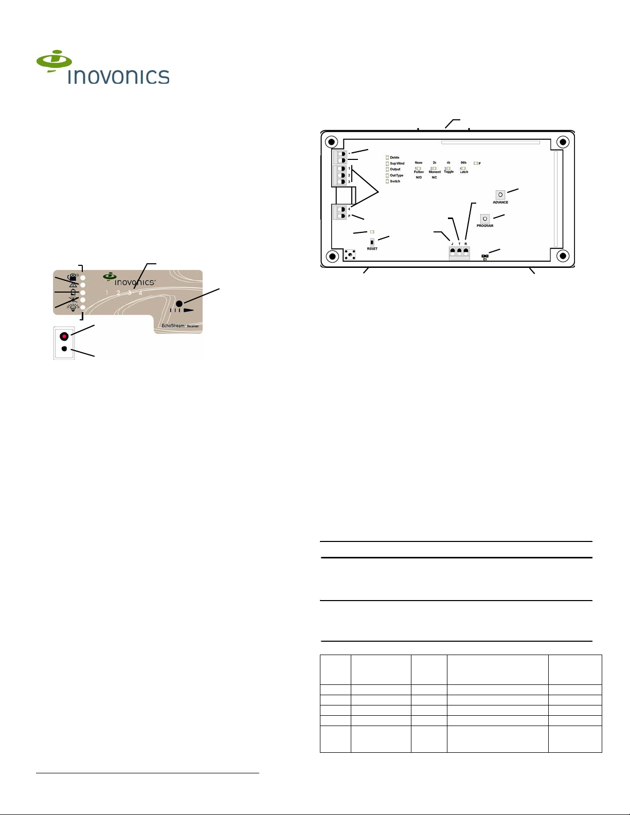
1.2 EE4204 LEDs and Buttons
A
B
C
D
E
H
I
Figure 1 Receiver LEDs and Buttons
A Alarm LED B Tamper Fault LED C Low Battery Fault LED
D Inactive Fault LED E Power LED F Transmitter Number LEDs
G Advance Button H Decode LED I Reset Button
Most of the LEDs and buttons perform different function depending on
which mode the EE4204 is in.
Normal Operation Mode
Alarm LED: Lights when any transmitter is sending an alarm transmission.
Tamper Fault LED: Lights when any transmitter is sending a tamper
transmission.
Low Battery Fault LED: Lit when any transmitter has a low battery.
Inactive Fault LED: Lit when any transmitter is inactive.
Power LED: Lit when receiving power.
Transmitter Number LEDs: Lit when the transmitter is in alarm.
Advance Button: Press the Advance button to enter status review mode.
Decode LED: Flashes when any recognizable transmission is received.
This LED is only visible when the pry-out door or cover is removed.
Reset Button: Clears the current status for all points and resets all outputs
and LEDs. Resets the supervision window timers. This button is only
accessible when the pry-out door or cover is removed.
Status Review Mode
Alarm LED: Lights when the selected transmitter is sending an alarm
transmission.
Tamper Fault LED: Lights when the selected transmitter is sending a
tamper transmission.
Low Battery Fault LED: Lit when the selected transmitter has a low
battery.
Inactive Fault LED: Lit when the selected transmitter is inactive.
Power LED: Lit when receiving power.
Transmitter Number LEDs: Shows status of the transmitter assigned to
that number when lit. Use the advance button to scroll through transmitters.
Advance Button: Scrolls through transmitters to display status.
Decode LED: Flashes when any recognizable transmission is received.
This LED is only visible when the pry-out door or cover is removed.
Reset Button: Clears the current status for all points and resets all outputs
and LEDs. Resets the supervision window timers. This button is only
accessible when the pry-out door or cover is removed.
F
G
B
C
D
F
H
E
M
G
J
I
K
L
A
Figure 2 EE4204 Components
A Housing release
tabs
D Output terminals E Fault output F Advance button
G Reset button H Reset input I Jam output
J Tamper output K Program button L EchoStream Select
M Decode LED
B Power (11-14
VDC)
C Ground connection
compatibility selection pins
A
2 Installation and Startup
2.1 Connect Power Cabling
Before beginning startup, you will have to connect power to the receiver. To
connect power to the receiver:
1. Connect power cabling to the Power and GND connections.
• Power source should be 11-14 VDC. Power supply must be
unswitched, uninterrupted, and regulated.
2.2 Enable EchoStream Select
To meet ETSI requirements, Inovonics has developed a new line of EE
868MHz-only products. These new 868MHz-only products are compatible
with older systems that include EchoStream Select (ES) products. If you
are using any ES products in your current system, you will need to enable
EchoStream Select compatibility on this new 868MHz-only product.
To enable/disable EchoStream Select compatibility:
1. To enable compatibility with ES products, place a selection jumper on
the ES selection pins.
Note: Selection jumpers are included in the EE4204 hardware packet.
2. If no ES products are used in your system, remove the selection jumper
from the ES selection pins.
3. Cycle power.
2.3 Program the Receiver
Note: If changing programming for a point that already has a transmitter
registered to it, there is no need to re-register the transmitter. Changes to
point programming are automatically assigned to the transmitter registered
to that point.
The default settings are:
Point Supervision
Window
1 4 hours 1 Follow N/O
2 4 hours 2 Follow N/O
3 4 hours 3 Follow N/O
4 4 hours 4 Follow N/O
F N/A Fault Inactive is set to follow; low
Output Type Switch
(EE4204
Only)
battery and tamper are set
to latching.
N/O
© Inovonics, 2011 - www.inovonics.com
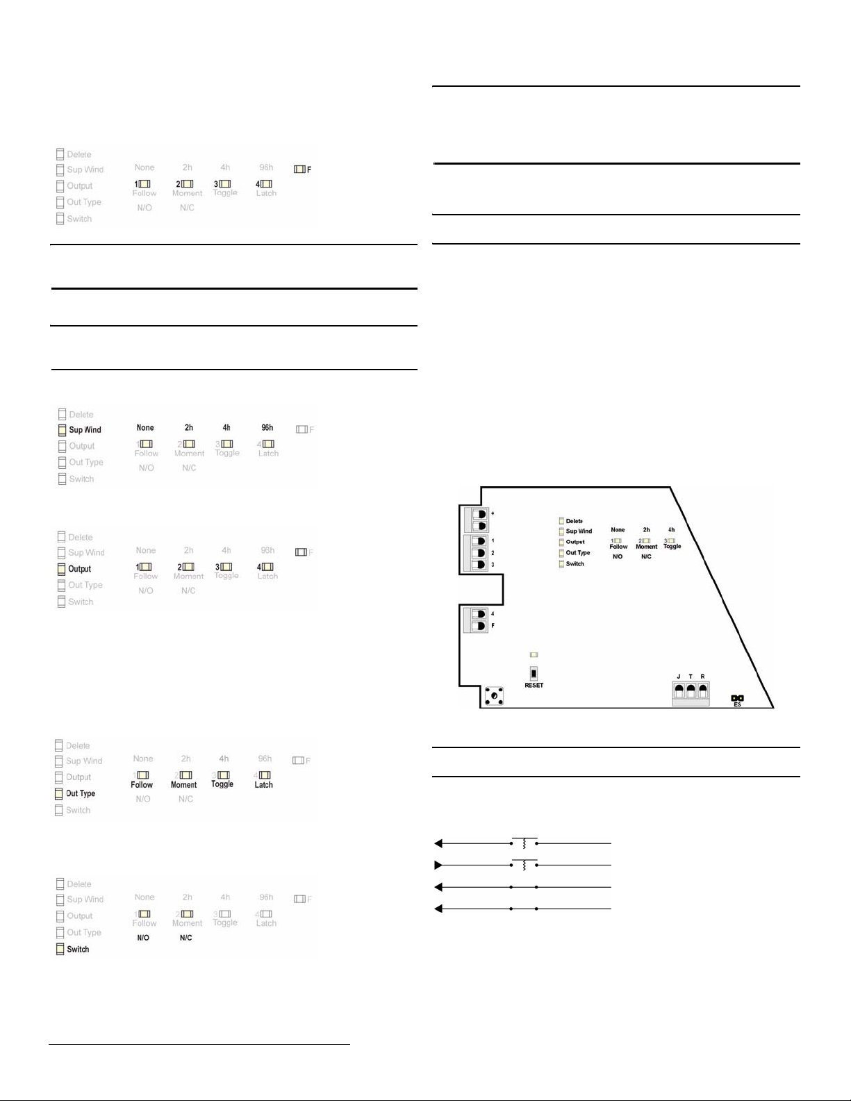
To program any of the four transmitter points or the fault output:
1. Use a small screwdriver to press the housing release tab on either side
of the receiver; separate the housing.
2. Use the Advance button to select any of the four transmitter points or
the fault output (Fig. 3).:
Figure 3 Select the Output to Program
Note: The only programmable parameter on the fault output is whether the
output is normally open or normally closed. If F is selected, the EE4204
automatically advances to the switch option.
3. Press the Program button to begin programming the point. If no
transmitter has been registered to the chosen point, the receiver
advances to the supervision window option.
Note: If a transmitter has already been registered to the chosen point, the
Delete LED lights. Press Advance to delete the point and return to normal
operation; press Program to advance to the supervision window option.
4. Use the Advance button to choose a supervision window of None, 2h,
4h and 96h. Press Program to complete and advance to the output
option (Fig. 4).
Figure 4 Select the Supervision Window
5. Use the Advance button to select the output number (Fig. 5). Press
Program to complete and advance to output type option.
Figure 5 Select the Output Number
6. Use the Advance button to select the output type (Fig. 6). There are
four output types:
Follower: The output reflects the transmitter’s alarm status.
Momentary: The output turns on for seven seconds, then turns off,
regardless of the device status.
Toggle: The output changes state each time the device sends a new
activation. A minimum of four seconds must elapse before the output can
send a new activation.
Latching: The output turns on when activated and remains on until the
receiver is reset.
Figure 6 Select the Output Type
Press Program to complete and advance to the switch type option.
7. Use the Advance button to choose between N/O and N/C (Fig. 7).
Press Program to complete..
Note: All of the alert LEDs will turn off when the receiver has received the
transmitter’s registration message, and the point number LED will light for
two seconds. The registration is not complete until all LEDs turn off and the
point number lights, indicating the receiver has received the transmitter’s
registration message. If this does not occur, press Reset on the transmitter
again.
2.4 Factory Config
The factory config option is used to restore the EE4204 to it factory
defaults.
Caution: The factory config will erase all programmed point, output, and
language information.
To restore the factory configuration defaults to the EE4204:
1. Hold down the Reset and Advance buttons.
2. With the buttons held down, cycle EE4204 power.
3 Connect Input/Output Cabling
1. Connect cabling to the tamper output.
• The optional tamper output is a normally open (N/O) output that
reports receiver case tamper to an external device.
2. Connect cabling to the jam output.
• The optional jam output is a normally closed (N/C) output that opens
when noise thresholds on all transmission channels remain above a
predetermined value for any 30 seconds in any 60 second window.
The jam output is set to the follow output type.
3. Connect cabling to the reset input.
• The optional reset input circuit permits installation of a remote
momentary normally open (N/O) switch to clear faults, unlatch outputs
and reset the receiver to a normal state.
4. Connect cabling to the output terminals.
5. Close receiver housing.
Vs
Ground
Output 1
Output 2
Output 3
Caution: Incorrect
connections may
cause damage to the
Output 4
Fault
Figure 8 EE4204 Terminals
3.1 Mount the Receiver
Caution: Mount the receiver in a location removed from metal. Metal
objects (duct work, wire mesh screens, boxes) will reduce RF range.
1. Use the provided anchors and screws to mount the receiver in a
location accessible for future maintenance.
2. Perform a walk test, activating each transmitter assigned to the receiver
and ensuring an appopriate response.
unit
Jam output
Tamper output
Reset input
Figure 9 Tamper, Reset, and Jam Circuits
Figure 7 Select the Switch Type
8. All the option LEDs will light and the point you’ve just programmed will
flash. If you wish to register a transmitter to the point you’ve just
programmed, press the transmitter’s Reset button; otherwise, press
Program to save programming changes without registering a
transmitter.
© Inovonics, 2011 - www.inovonics.com 2
 Loading...