

EE1702 Dual Analog Sensor Transmitter
Installation Instructions - 05313B
1 Overview
The EE1702 transmits analog data from one or two external sensors.
1.1 Inovonics Wireless Contact Information
If you have any problems with this procedure, contact Inovonics Wireless technical
services:
• E-mail: support@inovonics.com
• Phone: (800) 782-2709; (303) 939-9336
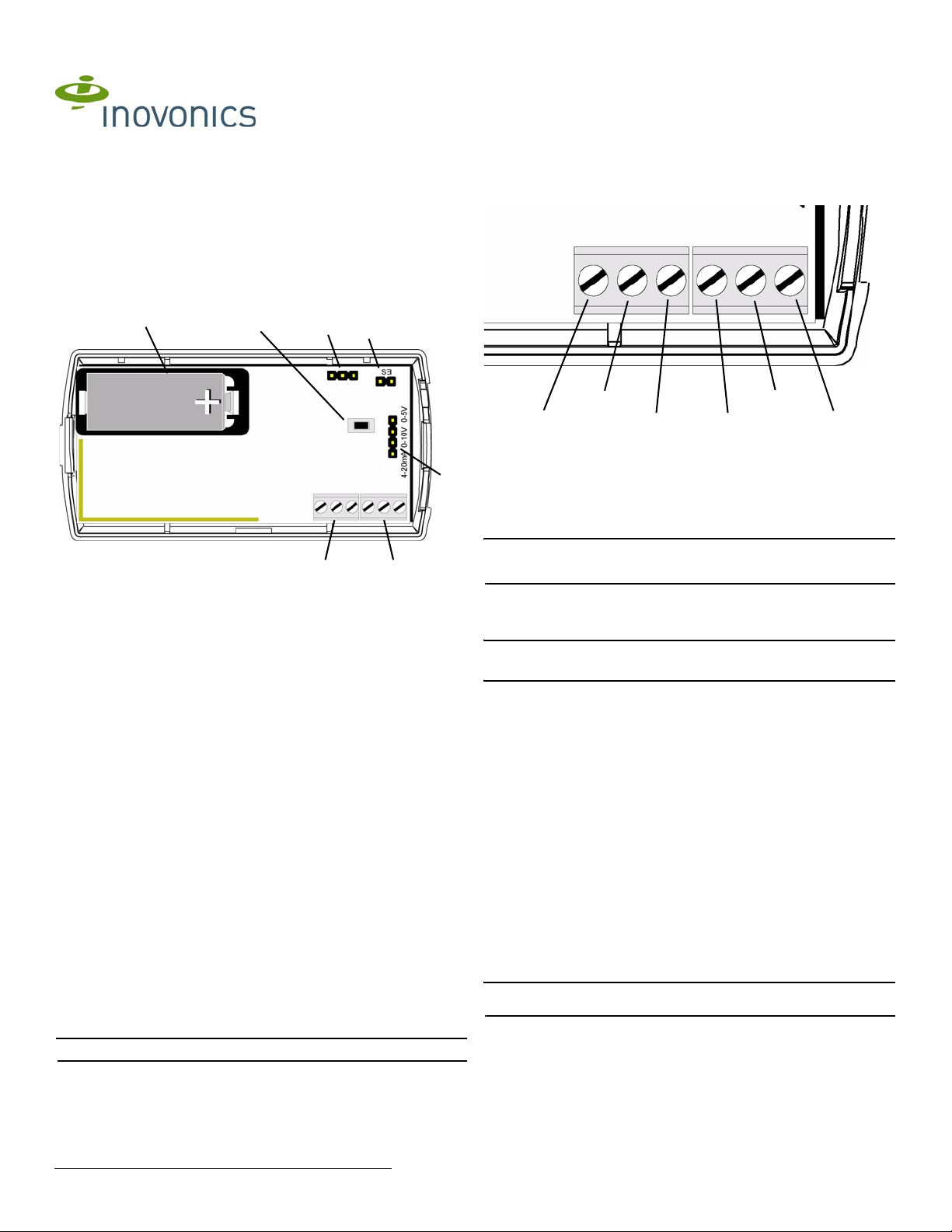
1.2 EE1702 Components
F
E
G
D
3 Program the Transmitter
EE1702 transmitters are programmed at the factory. It is not usually necessary to
reprogram EE1702 series transmitters. If you want to reprogram the transmitter,
parameters can be changed using the programming header.
C
A
Figure 1 EE1702 Components
A First external sensor
terminal block
D ES selection pins E Reset button F Battery
G Programming header
B Second external sensor
terminal block
C Sensor output selection
B
pins
2 Installation and Startup
2.1 Install/Replace the Battery
1. Pry the top lip of the mounting bracket up, and lift the bracket off of the t ransmitter.
2. Use your thumb to depress the housing release tab on the bottom of the
transmitter; separate the housing.
3. If replacing a battery, use the hol e i n the back of the housing to push the old
battery out of the battery holder.
4. Install the new battery.
5. Press the Reset button to initialize the transmitter. If replacing a battery, the
transmitter’s most recent programming will be restored upon initialization.
2.2 Enable EchoStream Select
To meet ETSI requirements, Inovonics has developed a new line of EE 868MHz-only
products. These new 868MHz-only products are compat ible with older systems that
include EchoStream select product s. If you ar e using any ES product s in your current
system, you will need to enable EchoStream select compatibility on this new 868MHzonly product.
To enable/disable EchoStream select compatibility:
1. To enable compatibility with ES products, place a selection jumper on the ES
selection pins.
2. If no ES products are used in your system, remove the selection jumper from the
ES selection pins.
2.3 Attach the Analog Sensors and Select Output
To use the EE1702, you must connect the analog sensor(s) to one or both of the
terminal blocks. To connect the analog sensors:
1. Place a selection jumper on the appropriate sensor output selection pins (Fig.
1C).
• Place the jumper on the bottom two pins, to select a sensor output of 4-20mA.
• Place the jumper on the middle two pins, to select a sensor range of 0-10V.
• Place the jumper on the top two pins to select a sensor range of 0-5V.
2. Referring to Figure 2, use a small screwdriver to attach the external sensor(s)
wiring leads to the appropriate terminal blocks.
The analog sensor cable length must not exceed one meter.
3. If the battery has been installed, press the Reset button to complete the
procedure.
GND
4-20 mA
0-10V
0-5V
GND
4-20 mA
0-10V
0-5V
First Sensor Second Sensor
Figure 2 EE1702 External Sensor Wiring
4 Mount the Transmitter
1. Attach the mounting bracket to the wall, using either screws or double-sided tape.
There are two mounting holes for standard installation. An optional third mounting hole
is located under the battery. Use the third mounting hole to secure the housing to the
bracket.
2. Hook the bottom of the transmitter into the bracket’s bottom catch, and press the
transmitter into the bracket so that the bracket’s top lip snaps into place.
5 Warranty/Disclaimer
Caution: Changes or modifications to this unit not expressly approved by Inovonics
Wireless Corporation may void the installer's authority to operate the equipment as
well as the product warranty.
Inovonics Wireless Corporation ("Inovonics") warrants its EchoStream products
("Product" or "Products") to conform to its own specifications and to be free of defects
in materials and workmanship under normal use for a period of thirty-six (36) months
from the date of manufacture. Within the warranty period, Inovonics will repair or
replace, at its option, all or any part of the warranted Product. Inovonics will not be
responsible for dismantling and/or reinstallation charges. To exercise the warranty, the
User ("User", "Installer" or "Consumer") must work directly through their authorized
distributor who will be given a Return Material Authorization ("RMA") number by
Inovonics. Details of shipment will be arranged directly through the authorized
distributor.
This warranty is void in cases of improper installation, misuse, failure to follow
installation and operating instructions, alteration, accident or tampering, and repair by
anyone other than Inovonics.
This warranty is exclusive and expressly in lieu of all other warranties, obligations or
liabilities, whether written, oral, express, or implied. There is no warranty by Inovonics
that Inovonics product will be merchantable or fit for any particular purpose, nor is
there any other warranty, expressed or implied, except as such is expressly set forth
herein. In no event shall Inovonics be liable for an incidental, consequential, indirect,
special, or exemplary damages, including but not limited to loss of profit, revenue, or
contract, loss of use, cost of down time, or interruption of business, nor any claim
made by distributor's customers or any other person or entity.
This warranty will not be modified or extended. Inovonics does not authorize any
person to act on its behalf to modify or extend this warranty.
This warranty will apply only to Inovonics Products. Inovonics will not be liable for any
direct, incidental, or consequential damage or loss whatsoever, caused by the
malfunction of Product due to products, accessories, or attachments of other
manufacturers, including batteries, used in conjunction with Inovonics Products.
The CE Declaration of Conformity can be found here: www.inovonics.com//euro/pdf/
declaration_conformity.pdf
© Inovonics, 2009 - www.inovonics.com
 Loading...