

Inovonics EE1243 User Manual
EE1243 EchoStream® Smoke Detector
B
A
A
B
C
Battery
Compartment
Cover
Transmitter
Installation Instructions
1 Overview
The EE1243 smoke detector is a wireless, battery powered photoelectric
smoke sensor. The sensor includes a built-in sounder for alarm alerts, a
visual status LED, a back tamper , and an Inovonics transmitter. The sensor
works as part of a security/fire alarm system and communicates with the
system control panel. Under normal (non-alarm) conditions, the LED
flashes once every eight seconds while the sensor monitors the
surrounding conditions. When the sensor detects smoke, the LED lights,
the built-in sounder beeps loudly, and an alarm signal is transmitted. The
smoke sensor is powered by the two included three-volt lithium batteries.
When the EE1243 detects an inactive smoke sensor a tamper message will
be transmitted.
1.1 Inovonics Wireless Contact Information
If you have any problems with this procedure, contact Inovonics Wireless
technical services:
• E-mail: support@inovonics.com
• Phone: (800) 782-2709; (303) 939-9336
1.2 EE1243 External Components
Figure 1 EE1243 external components
A LED B Test/silence button
Status LED: The LED indicates the status of the sensor as follows:
• LED flashes every 8 seconds to indicate normal operation.
• LED stays on when the sensor detects smoke, and is sending an
alarm.
• LED stays off when maintenance is required.
Test/silence button: Test/silence is pressed to perform the sensitivity test,
as well as to silence the low battery chirp. The low battery chirp will resume
after 24 hours if the condition is not corrected.
1.3 EE1243 Internal Components
1.4 What’s In The Carton
• Two BAT604 Duracell DL123A lithium batteries
• Two drywall anchors
• Two mounting screws
• Two frequency band selection jumpers
2 Installation and Startup
2.1 Installation Notes
• These products are designed to be maintained by professional
security technicians
• Products are tested for indoor use
• All products should be manually tested weekly
2.2 Install Batteries
1. Turn the sensor housing counterclockwise fifteen degrees and detach it
from the mounting base.
2. Remove the battery compartment cover.
Figure 3 Remove the EE1243 battery compartment cover
3. Install the two three-volt batteries.
4. Replace the battery compartment cover
Note: A tamper message will transmit for approximately ten seconds while
the unit powers up after the installation of both batteries. If only one battery
is installed, the tamper message will transmit continuously.
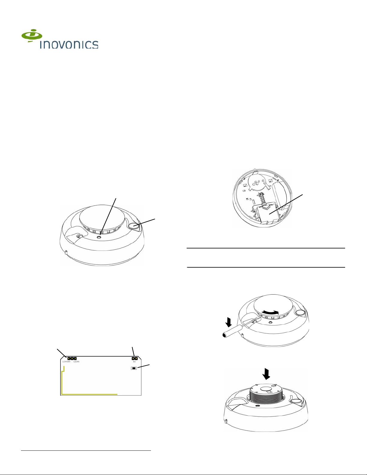
2.3 Open the Housing
5. Using a small screwdriver to press the sensor cap release tab, apply
downward pressure and turn the cap about one inch counter-clockwise
to remove the cap..
Figure 2 EE1243 internal components
A Low battery/CleanMe
selection pins
5.21.14 06598A © Inovonics, 2014 - www.inovonics.com
B EchoStream select
compatibility selection
pins
C Reset button
Figure 4 Remove the sensor cap
6. Place both thumbs on either side of the optical chamber and push down
to detach the sensor housing.
Figure 5 Push down on the optical chamber

2.4 Enable EchoStream Select
To meet ETSI requirements, Inovonics has developed a new line of EE
868MHz-only products. These new 868MHz-only products are compatible
with older systems that include EchoStream select products. If you are
using any ES products in your current system, you will need to enable
EchoStream select compatibility on this new 868MHz-only product; if you
are not using any EchoStream select products, skip to section 2.5, “Set
CleanMe®/Low Battery Reporting”.
To enable compatibility with ES products:
7. Place a selection jumper on the enable EchoStream selection pins.
2.5 Set CleanMe®/Low Battery Reporting
Set as the factory default, the EE1243 combines the low battery signal with
a signal indicating the detector needs cleaning. If you want to use this
multiple condition indication, skip to 2.6, “Register the EE1243”. If multiplecondition indication is not desired, you can disable wireless reporting of the
CleanMe status.
8. To disable CleanMe reporting, move the jumper on the low battery/
CleanMe selection pins to Low Bat.
Note: Low battery/CleanMe messages are suppressed when an alarm is
being transmitted.
Note: Even if CleanMe notification is disabled, the sensitivity test will still
indicate sensor condition.
2.6 Register the EE1243
The EE1243 must be registered to function in your EchoStream system.
Refer to your receiver, network coordinator or control panel manual for
registration instructions. Inovonics Wireless recommends all EchoStream
transmitters be supervised.
9. When prompted, press the EE1243 reset button to complete
registration.
2.7 Mount the EE1243
10. Use the provided anchors and screws to mount the EE1243, paying
careful consideration to the following best practices:
Caution: Regulations pertaining to smoke sensor installations vary. For
more information, contact your local fire department or local authority
having jurisdiction.
• Install a minimum of two smoke sensors in any household.
• Put a smoke sensor in the hallway outside of every bedroom area.
• Put a smoke sensor on every level of a multi-level residence.
• In rooms with sloped ceilings, install smoke sensors 0.9m (3 feet)
measured down from the highest point of the ceiling.
• Install basement sensors on the ceiling as close to the center of the
room as possible. If this is not practical, install on the ceiling no closer
than 10cm (4 inches) from any wall or corner.
• If ceiling mounting is not practical, install on an inside wall between 10
an 15cm (4 and 6 inches) from the ceiling.
• Put smoke sensors at both ends of a bedroom hallway if the hallway is
more than 9m (30 feet) long. Large rooms over 84 square meters (900
square feet) require more than a single sensor.
• Areas with rough ceilings or short, transom-type walls coming down
from the ceiling require additional smoke sensors.
• Install second-floor smoke sensors on the ceiling at the top of the firstto-second floor stairwell. Be sure that no door or other obstruction
blocks the path of smoke to the sensor.
Do not locate sensors:
• To a drop ceiling tile; mount it to a metal runner.
• In or near areas such as kitchens or garages, where smoke or vehicle
exhausts normally occur (protect these areas with heat-detection
devices, not with smoke sensors); near furnaces, hot water heaters,
or gas space heaters.
• In damp or very humid areas, or next to bathrooms with showers.
Install sensors at least 1.5m (5 feet) away from bathrooms.
• In very cold or very hot areas.
• In dusty, dirty, or insect infested areas.
• Near fresh air inlets or returns or excessively drafty areas. Air
conditioners, heater, fans, and fresh air intakes and returns can drive
smoke away from smoke sensors.
• In dead air spaces at the top of a peaked ceiling or wall/ ceiling
intersect. Dead air may prevent smoke from reaching a smoke sensor.
• Near fluorescent light fixtures. Install smoke sensors at least 3m (10
feet) away from fluorescent light fixtures.
• Between protruding ceiling structures such as beams or walls which
can create dead air spaces and may prohibit smoke from reaching the
detector.
Caution: All sensors are subject to possible compromise or failure-to-warn
for a variety of reasons. For example: Smoke sensors cannot detect smoke
in chimneys, walls, roofs, or smoke blocked by a closed door; sensors may
not detect smoke on other levels of the building; sensors may not warn in
time when fires are caused by smoking in bed, explosions, improper
storage of flammables, overloaded electrical circuits, or other hazardous
conditions.
3 Test the EE1243
Caution: To avoid a fire department dispatch, contact the central
monitoring station or, if possible, put the system into sensor test mode.
There are two ways to test the EE1243 smoke detector sensor. The
sensitivity test should be performed every week; the smoke test should be
performed at least once a year. Both tests activate the alarm sounder and
send alarm signals.
The EE1243 should also be tested after initial registration, as well as each
time the smoke chamber is changed or the batteries are replaced.
3.1 Smoke Test
1. Use aerosol simulated smoke, such as ESL Smoke! In a Can® (ESL
Part No. SM-200) to perform the smoke test.
The LED will remain on while the built-in transmitter sends an alarm signal,
and the sensor will produce a three-beep pattern.
2. Press the test/silence button to end the test.
The sensor automatically resets when smoke is no longer present. A
sensor that fails to activate may require cleaning. If a sensor still fails to
activate after cleaning, return the unit for service.
3.2 Sensitivity Test
1. Press and hold the test button for four seconds, then release it. The
LED will flash corresponding to the sensor’s sensitivity.
Flashes Sensor Condition/Action
1 Self-diagnostics failure. Return sensor for service/
2-3 Sensor is becoming insensitive. Clean the sensor (see
4-7 Sensor is within normal sensitivity range.
8-9 Sensor is becoming too sensitive. Verify that the smoke
During this test, the control panel, serial receiver or network coordinator
should receive an alarm and a low battery signal, if low battery is selected,
followed a few seconds later by a restoral.
If the control device fails to respond, it is possible the EE1243 failed to
reset properly when the batteries were installed. To force a reset, remove
the batteries from the EE1243 for a least 30 seconds, reinstall them, press
the reset button, then retest as described above.
replacement.
“Clean the EE1243”) and retest. If error persists, replace
sensor.
chamber is snapped down securely. Clean the sensor and
retest.
4 Clean the EE1243
Clean the sensor cover with a dry or damp cloth as needed to keep it free
from dust and dirt. Clean the sensor interior and replace the optical
chamber at least once each year. Use only ESL model 211 optical
chambers for replacement. To clean the sensor chamber:
1. Remove the sensor body from the mounting base.
2. Remove the batteries.
3. Slide a flat-blade screwdriver in the slot on the sensor cap and gently
push the handle down to pry the cap off.
4. Squeeze the optical chamber where indicated and pull it up and away
from the sensor. Discard.
5. Use a soft-bristled brush to remove dust and dirt from the smoke
chamber base.
6. Align the new optical chamber with the base and snap it down into
place.
7. Replace the sensor cap.
8. Reinstall the batteries.
9. Replace the battery cover.
5.21.14 06598A © Inovonics, 2014 - www.inovonics.com 2
 Loading...