


Data Concentrator and Communicator
Installation Guide
Introduction
The Data Concentrator and Communicator (DCC) is installed at the submetering site’s head-end
location to collect data from the transmitters using either the FA403 or the EN6540 receiver. It
can communicate with the billing service using a modem, or with an onsite technician’s computer
using a serial port. This allows the service technician to easily make changes to the site
information in the DCC, as well as to perform site data entry, data retrieval and trouble-shooting.
Inovonics Contact Information
If you have any problems with this installation, contact Inovonics techical support:
• E-mail: support@inovonics.com
• Phone: (800) 782-2709
DCC Installation Instructions
Note: Use the DCC Installation Diagram on page 3 with these instructions to install the Data
Concentrator and Communicator.
1. Using the anchors and screws provided, mount the receiver in a building where the
temperature will remain within 32° to 140°F (0° to 60°C), non-condensing.
• Typically, the higher the receiver is mounted, the better the RF reception. The receiver is
generally mounted at a height of six to seven feet.
• Mount the receiver in a location removed from metal. Metal objects (duct work, wire mesh
screens, boxes) will reduce RF range.
• Mount the receiver in a location where it will be accessible for future maintenance.
Caution: Neither the receiver or the DCC should ever be installed at floor level.
2. Using the anchors and screws provided, mount the DCC within 100 feet of the receiver, in a
location near phone lines and a standard 120 VAC wall outlet.
3. Connect the receiver to the DCC using 4-conductor, 22 gauge, unshielded wire with a
maximum length of 100 feet.
© 2005 Inovonics Wireless - Document #02962D
DCC Installation Instructions
4. Connect the phone line from the screw terminals on a hardwired wall bracket to the terminal
blocks on the DCC.
• The phone line should be connected to the telephone wall outlet using the screw terminals.
The RJ11 plug-in phone connector is provided for easy access to the phone line during
future on-site maintenance.
5. Use 18 or 20-guage wire to connect 14 VAC power to the DCC with the provided transformer.
• Circuit protection is built into the DCC.
6. Use the provided screw to secure the transformer to the outlet.
Note: Telephone and power connections should be as mechanically robust as possible, and protected
from accidental disconnection.
Caution: Wiring should exit through the back of the DCC, be cut to length, and stapled neatly to the wall
to reduce the possibility of personal injury or equipment damage.
7. The FA403 requires no additional setup. If you are using an FA403, the installation is
complete. If you are using the EN6540, advance to the next section.
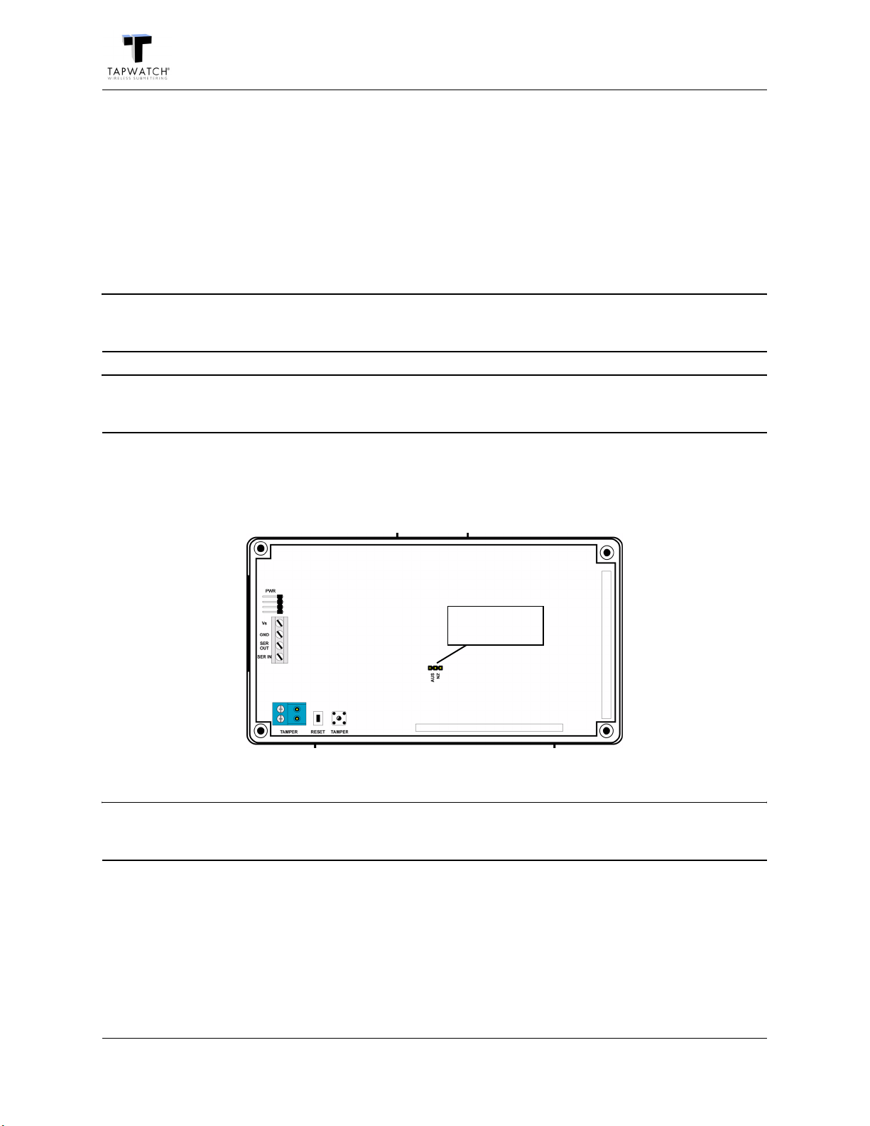
EN6540 Installation Instructions
Frequency band
selection pins
Figure 1 EN6540 Components
Note: Connecting an external tamper switch on the EN6540 is not necessary. The external tamper switch
connector is not functional.
Select Frequency Band
EchoStream products are able to use a range of radio frequencies, and must be configured for
your geographic area. If you are using the EN6540 anywhere except North America, you will need
to select the frequency band appropriate to your geographic area. All EchoStream receivers are set
for North America by default. If you are using the EN6540 in North America, there is no need to
select the frequency band.
1. Use a small screwdriver to press the housing release tab; open the housing.
2 © 2005 Inovonics Wireless- Document #02962D
 Loading...