


INSTRUCTION
MANUAL
MODEL
375
TAPE
RECORDING
ELECTRONICS
August,
1975
0-
INOVONICS
1630
DELL
AVE
.,
CAMPBELL,
CALIF
95008
INCORPORATEO
(408)
374·8300

TABLE
OF
CONTENTS
SECTION
1.0
2.0
3.0
4.0
GENERAL
INSTALLATION
OPERATIJN
ALIGNMENT
PARTS
SCHEMATICS.
INFORMATION
AND
USE
AND
FUNCTIONAL
AND
MAINTENANCE
LIST.
........
. . . . . . . .
DESCRIPTION
PAGE
.
2
7
9
·
17
·
23
•
28

SECTION
1.0
GENERAL
INFORMATION
The
lnovonics
375
is
a compact, up-to-date magnetic recording
elec-
tronicspackage, completely self-contained with
integral
power
supply.
Available in several versions, the
375
is
equally well suited to
new
installations,
or to
improve
the performance
and
reliability
of
older
professional tape recorders.
The
375
is
delivered with proper interconnect cabling for whatever
tape
transport
is
specified
for
use
with
it.
When
no
specification
is
made,
the unit
is
supplied with cabling for
Ampex
350/351
series
mqchines.
Among
the features incorporated are:
Calibrated positions
on
Record
and
Reproduce
gain
controls.
Provision for remote switching
of
all
monitor
and
equalization
functions,
and
solid-state
switching to eliminate contact noise
problems.
3-speed equalization to
accommodate
any
combination of
NAB
and
IEC
characteristics.
Harmonic
and
phase
distortion
nulling
circuits.
Able
to
accommodate a wide
variety
of
original-equipment
and
replacement heads.
Optional
SYNC
Reproduce
Amplifier with independent equalization
and
automatic
SYNC-INPUT
monitor
transfer
switching (-03 version
only).
-2-

1.1
SPECIFICATIONS
NOTE:
by
for upgrading older recorders in broadcast
as well
cations are given, each with respect to the heads, tape
generally in use in each
tains
1.1.1 Specifications derived using
replacement
Frequency
Signal-to-Noise
Performance
the
heads
as
those
of
and
tape employed. ihe Inovonics
for
new
studio
specifications
head
Response
3.75
assembly
;
ps
15
ips
7.5
ips
Ratio (in
(in
a magnetic recording system
375
and
similar
installations.
installation
which
on
an
Ampex
Hz)
+2dB
+2dB
+3dB
dB,
referred
are not
3M
Hence
situation.
application
206
tape
351
t , ansport.
a "peak"
to
two
and
20
20
20
is
limited in
is
sets
A
third
oriented.
a Taber
20k
15k
8k
-
record 1evel
part
intended both
applications,
of
specifi-
and
standards
group con-
full
track
6dB
above
3.75 ips
Erase/Bias Frequency
100kHz
Erasure
70dB
saturation.
200nW/m,
15
ips
7.5 ips
erasure
or
approx.
OVERALL
u'wtd.
-67 -76 -76
-69 -77
-66 -74
of
500Hz
3dB
below
NAB
wtd.
signal recorded
3%
THO;
STANDBY
u'wtd.
-76
-72 -83
3dB
below
20Hz -20kHz)
NAB
wtd.
-87
-86
tape
--
-3-

Recorded
Distortion
(at
15-mil
wavelength bias
LIN
out
peak -typical)
LIN
in
1.1.2
of
320nW/m
duce)
Operating
6dB
above
8dB
above
10dB
above
Specifications derived using
and
heads
- 70-mil
Level
Op
Level
Op
Level
Op
Level
Nortronics
track
cations.
Frequency
Response
30
ips
ips
15
(i n
Hz)
7.5 ips
Signal-to-Noise Ratio (in
20Hz -20kHz)
u 'wtd. wtd. u 'wtd. wtd.
.45%
2%
3%
5.5%
3M
250
tape,
9227
(erase),
9203
(record)
width format, typical
+2dB
+2dB
+2dB
dB,
referred
OVERALL
60 -22k
30 -22k
20 ~ 16k
to approx.
SYNC
.02%
.015%
.02%
2.2%
an
Operatinq
and
of
multi-track
(SYNC
640nW/m
Level
9213
(repro-
appli-
reproduce
response essentially
to
or
identical
normal
3%
THO;
overall)
STANDBY
u'wtd. wtd.
30
ips
15
ips
7.5 ips
Erase/Bias Frequency
250kHz
Erasure
lOdB
level,
erasure
or approximately
-71
-67
-67 -76
of
500Hz
-78 -71 -80 -80 -87
-77
signal recorded
3dB
-4-
-67
-67 -77
below
-77
12dB
tape
above
saturation.
-75 -86
-74 -85
Operating

Recorded
Distortion
(at
IS-mil wavelenth bias
LIN
out
peak -typical)
LIN
,in
Operating
3dB
above
6dB·above
Level
Op
Level
Op
Level
.5%
1%
2.5%
1.1.3 Specifications Independent of Application
Equalization
3 speed with pushbutton
tween
modates
30
INTER
and
NAB,
LOW
lEe
ips operation.
(or
when
mixed)
selection,
transport
characteristics
automatic switching beprovides closure.
Amplifier Distortion
Record:
~.1%
<:.25%
THO
THO
at
Op
25dB
Level
above
Op
Level
.15%
.3%
.8%
for
Accom-
3.75 through
Input '
Outputs
Reproduce:
<:.1%
~.5%
THO
THD
Sensitivity:
Impedance:
Line
Out~ut:
Headphones:
at
Op
Level
at
+24dBm
-20 to
Line Output (clipping level
+8dBm
input transformer)
10K
bridging
feeds
terminated
600
line,
or
Front panel jack
(-8
to ,-f:8dBm
balanced
not,
at
+4
with
or
or
-01
unbalanced,
+8dBm
+25dBm)
option
for
Zero-VU.
-5-

Panel
Controls
RECORD
GAIN
(with
pre-set
CAL
position)
REPRO
LEVEL
(with
pre-set
CAL
position)
MONITOR:
selects
between
INPUT,
REPRO
and
SYNC
(-03 versions)
SAFE/READY
RECORD
EQUALIZATION:
manual
selection of
HIGH,
INTER
or
LOW.
POWER
Power
Requirement
105-130
VAC
(230V
available)
SO/60Hz,
.3A
(plus transport)
Size
and
Shipping
Weight
x
19
11
3~1I
X
10"
15 1bs
-6-

SECTION
2.0
INSTALLATION
AND
USE
2.1
Upon
receipt
of
the equipment, inspect for shipping
damage.
Should
any
be
observed, notify the
carrier
immediately;
if
not,
proceed
as
outlined
below.
It
is
suggested
that
the
original
ship-
ping carton
and
materials
be
saved for possible future reshipment.
2.2
The
375
is
packaged to
mount
in a standard 19-inch equipment
rack, requiring
3~-inches
of
panel space.
When
replacing
original
electronics
in
an
overbridge
above
the
transport,
it
may
be
necess-
ary to
drill
and
tap
an
additional
two
holes to
accommodate
the
375
panel.
2.3
The
signal,
head
and
transport
connectors are
directly
compati-
b'~
with
Ampex
350,
351
and
354
equipment. Units ordered
for
use
with
other
transports-
or for use in
stereo
pairs are supplied with
appropriate interconnect cabling.
2.4 Unless supplied otherwise to special order,
units
intended for
mono
or
stereo
installations
are delivered properly aligned for
use
with
3M
206
tape
at
an
operating level
of
200nW/m,
with
Ampex
351-
type
heads
(1.
5mHy
erase,
5-10mHy
record
,and
·lHy reprod'lce)
and
100kHz
bias. Units for
multi-track
use
normally operate with lower
inductance
heads
(O.5mHy
erase,
4-5mHy
record,
and
400mHy
reproduce),
utilize
250kHz
bias,
and
incorporate the optional
SYNC
reproduce
amp-
lifier:
Heads
with inductances other than those suggested
above
can
be
accommodated.
Section
4.1.4.2
outlines
the necessary changes.
2.5
As
delivered, the
375
is
calibrated
to operate
at a +4dBm
signal
level.
Should
operation
at
+8dBm
be
necessary,
clip
the jumper
shun-
tingthe
4.7K
resistor
near the
line
output connector
and
recalibrate
as described in paragraph
4.1.2.8.
2.6
The
low
source
impedance
of
the
375
line
output
results
in only
about
~dB
level
change
from
an
unloaded to
600
ohm
loaded condition .
._.
-7-

The
375
should,
nevertheless,
be
connected to
its
intended load
prior
to final
calibration.
2.7
Even
with the optional input
isolation
transformer option sup-
plied (-01 version
only),
the
375
input impedance
is
10K
ohms
or
greater.
Should the equipment feeding the
375
require
a terminating
load, a
600-ohm
resistor
should
be
placed in
parallel
with the
375
input.
2.8
No
provision for meter
indication
of
bias
or
erase
current
is
made,
as
the inherent
stability
of
the
circuitry
is
greater
than
that
of
the
heads
and
meter
at
bias frequencies.
2.9
When
two
Ot'
more
375's are
employed
in dual
or
multi-track
ap-
plications,
the interconnecting cablinq supplied
delivers
AC
power
to
all
units
and
to the
transport,
if
it
derives
power
from
the
elect-
ronics.
The
cabling also "slaves"
all
erase/bias
amplifiers
to a
single
oscillator,
thereby avoid-ing bias "beats"
or
the
necessity
of
synchronizing
two
or
more
oscillators.
-8-

SECTION
3.0
OPERATION
AND
FUNCTIONAL
DESCRIPTION
3.1
OPERATION
3.1.1
The
RECORD
GAIN
and
REPRO
LEVEL
controls are provided with a
detented
CAL
position
at
full
CCW
rotation.
They
are normally
left
in these positions except for temporary correction
for
an
improperly
recorded tape
or
abnormal
line
level.
Range
is
adequate to record
from a -20dBm
line
level
(-8dBm
with optional input transformer)
and
to produce
normal
line
output
from
a tape under-recorded
by
10dB.
3.1.2
The
MONITOR
buttons determine whether the
line
amplifier will
derive
its
si9~al
from
the incoming
program
(INPUT),
the reproduce
head
(REPRO),
or in versions with
-03
option, the record
head
(SYNC).
When
any
button
is
only
slightly
depressed to
release
all
three to
their
"out"
position,
the monitor
selection
is
transferred
to the
rear
panel
REMOTE
connector.
On
versions with the -03 option,
mon-
itor
is
automatically switched
from
SYNC
to
INPUT
when
entering the
record
mode.
3.1.3
The
alternate-action
SAFE/READY
switch,
when
depressed, per-
mits the
375
to
enter
the record
mode
when
the
transport
is
in "record".
When
this
button
is
"out", the
375
will not
enter
the
recoY'd
mode,
thereby preventing accidental
erasure
of a tape or
that
track
of a dual
or
mult-track recording.
3.1.4
The
RECORD
button places the
transport
in the record
mode.
The
button will not illuminate, though,
nor
will
~he
375
go
into "record"
unless the
SAFE/READY
button
is
depressed.
In
dual
or
multi-track
in-
stallations,
depressing
any
RECORD
button will place the
transport
in
the record
mode;
only those
375 1 s in "ready" wi.l record,
however.
3.1.5
The
EQUALIZATION
buttons
select
record
and
reproduce equal-
lizationappropriate
to the
transport
speed
employed.
Three independ-
ent
sets
of
equalizers are provided, although
most
transports
are only
-9-

dual
a
European
speed
units.
or
other non-standard curve.
In
these cases the
third
In
position
may
be
used for
the event of use with a
transport providing
an
switch, the equalization
matically
wired)
between
by
depressing
INTER
an
three buttons are "out".
3.1.6
375
3.1.7
through a
or
3.1.8
and
as
The
alternate
to the
The
470
an
unbalanced, uncalibrated
The
transport,
PHONES
ohm
recessed
action
jack
resistor.
slide
enables or defeats the
equalization-switching pole
selection
and
LOW
EQUALIZATION
POWER
if
it
is
connected
It
can
be
transferred
(if
the
transport
button
slightly
switch controls
is
powered
ahead
is
suitable
line
by
of
for
output for servicing.
the
the output transformer
on
the speed
to change auto-
is
appropriately
so
that
AC
power
electronics.
headphone
monitoring
switch behind the adjustment cover panel
linearization
circuit,
(see paragraph
all
to the
4.2.1).
-10-

3.2
CIRCUIT
DESCRIPTIONS
3.2.1 General
Electronic
circuitry
for the Recording, Reproducing
and
Erasing
Amplifiers
iS
,contained
on a single
"piggy-backed" plug-in assembly.
The
lower board (Reproduce)
carries
the Reproduce, optional
SYNC
and
Line Amplifiers; the upper board (Record), the Erase/Bias
and
Record
Amplifiers. Another
single
PC
assembly within the chassis contains
the
power
supply
and
bias
oscillator
circuits.
3.2.2
Reproduce
Amplifier
(sche~atic
129000).
Signals
from
the reproduce
head
enter
on
pins
13
and
14.
An
option-
al
head
input transformer (-04 version only)
can
be
strapped in to
permit
use
of
low
(4-5mHy)
inductance heads. Resistor
Rl
is
selected
to
dampen
head
resonance
and
yield
smoothest playback response (see
paragraph
4.1.2.4).
Transistors
Ql
and
Q2
form
a complementary feedback-pair input stage,
Q3
serving primarily as
an
emitter-follower buffer.
DC
feedback
is
maintained through
RIg
and
Rll, bypassed
at
audio frequencies
by
C2.
AC
feedback .
is
routed througli
an
appropri
ate
equa
1i
zat ion
network
by
FET
switches
Q4,
Q5
or
Q6.
A secondary function
of
Q3
is
to provide
a phase-inverted reproduce signal
(at
the
collector)
for the repro-
duce
phase compensation
circuit.
This
signal,
coupled through
C7,
'
interacts
with the in-phase
emitter
signal fed through
R25
to provide
an
adjustment
of
reproduce phase
shift
to
complement
and
cancel the
phase
shift
which
normally occurs during the recording process.
FET
switch
Q7,
normally on, defeats
this
compensation, except
at
the
one
speed for
which
the adjustment
is
made
(see paragraph
4.2.2.2).
IC2
imparts voltage gain to the reproduce
signal,
with
R28,
the
REPRO
CAL
adjustment, providing a controi over the gain
and a means
of
obtain-
ing a given signal level for a
variety
of
head
outputs. This amplified
signal
is
fed through
R29,
bridged
by
the front panel
REPRO
LEVEL
con-
-11-

trol,
to the L ineAmpl
ifier.
3.2.3
The
tially
that
R53
gain. This
has
3.2.4
FET's
SYNC
Amplifier
optional
identi~al
the
is
increased over
head
SYNC
input transformer
is
greater
output than a
Line Amplifier
Q8,
Q9
and
required
Q28
Amplifier, passing
and
SYNC
Amplifier,
sistors
circuit
ground
are normally held
between
potential
the source
either
reproduce
to the
Reproduce
that
as
perform
signals
respectively.
at
by
amplifier
Amplifier
is
always used,
of
its
counterpart
the record
true
from
reproduce
an
input switching function for the Line
the
The
-20
volts,
and
drain.
the
front
(-03 version only)
head
used
head
Reproduce
just
discussed, except
and
the value
R3
to reduce overall
as
a reproduce
of
similar
Amplifier, input source,
gates of these switching
introducing
When
panel
MONITOR
the gate
an
effective
is
brought to
switch or through
is
essen-
of
head
inductance.
tran-
open
REMOTE
the
selected
Transistor
option (-03 version
INPUT
R34,
monitor
36,
beginning
might appear
IC1
performs the vcltage gain function
gain
Ql1
established
and
driving
short
circuits
connector, the source-drain
signal.
Q29
and
associated
when
C10
and
12
at
about
at
the
by
associated
low
impedance
is
only),
the
are
30kHz.
line
feedback
components
afforded
switching the
375
enters
part
This aids in reducing whatever bias signal
output, primarily in the
loads
and
by
resistance
circuitry
the record
of
an
resistors
is
active
of
R35
part
of
line
amplifier
mode.
low-pass
the Line Amplifier, with
and
37.
provide the output
long cables. Protection
diodes
CR3
and
4.
drops, passing the
the
SYNC
filter
SYNC
reproduce
Transistors
current
reproduce
from
SYNC
with
cutoff
mode.
Q10,
required for
from
output
to
-12-

3.2.5
Reproduce Line Amplifier
Although not
available
included in the
dedicated
option
3.2.6
Input
attenuated
R2
and
active
removes
mi
ght otherwi se cause
portion
ier
through
C4
imparts a 6dB/octave
to
is
relegated
Record
signals
by
R3,
capacitors
low-pass
RF
and
of
the mplified input signal
the reproduce function.
Amplifier (Schematic 129100)
from
the
other
RECORD
as a factory-installed
PC
artwork to incorporate a second Line Amplifier
Use
to
the
RECORD
filter
spurious
CAL
special
front
LEVEL
Cl
and 2 and
with
hi
gh
control
rising
applications
panel
RECORD-GAIN
calibration
first
cutoff
signals
beginning about
outside
frequency ollerl
is
R7
for
spurce monitoring.
characteristic
gain
directed
option,
of
this
or
user-installed
effects
control are
control,
stage
Rl. Resistors
ICI
30kHz.
the audible range
oad-j
ng
duri
ng
to the Line Amplif-
to
the
imput signal as
provision
generation.
form
recordi
is
further
an
The
filter
which
ng.
A
for
required
and
equalization
recording pre-emphasis. Depending
high frequencies
ted
in the feedback path
falling
zation
loop
falling
point
network
Rll
characteristic
trimmers
when
the
appropriate
characterisitc.
of
the
effective
characteristics.
and
C5
modify the pre-emphasis curve
characterisitc
or
no
increase
of
which
R34,
35
and
FET
This
pre-emprasis curve provided
used, however, only a
at
all
may
be
IC2,
therefore
cancels the
36
are introduced
switch
affords
is
control over
provides a complementary
effect
activated,
slightly,
upon
required.
of
C4.
into
the
and
the
by
causing a droop
in the 5kHz-and-above region. These component values
for
smoothest overall response, but
promise
for
heads typical
of
the
are
supplied as
application
for
the version
ed.
the tape speed
rise
at
very
C7,
connec-
Record
lC2
"shelf"
equali-
feedback
the
inflection
the
combined
can
be
changed
the
best
comorder-
-13-
0
---

A
3dB
boost
at
50Hz
(required
for
the
NAB
record
characteristic)
is
effected
by
shunting
C4
by
RIO.
FET
Q5
is
normally
off,
but
can
be
turned
on
for
one
or
more
equalization
positions
if
IEC
or
other
IIflat-low-end
ll
record curves are desired. This
is
accomplished
on
the
Power
Supply
PCB
(see paragraph
3.2.9).
CR3
and
4,
IC3,
and
associated
circuitry
forms
the
IIlinearizer
ll
net-
work.
When
Q9
is
turned
on
by
activating
the
LINEARITY
switch under
the adjustment cover panel, a
variable
non-linear
characteristic
can
be
imparted to the record signal
that
when
properly adjusted cancels
a major portion
of
the
tape-gener~ted
third
harmonic
distortion
(see
section
4.2.1).
1C4
and
associated
components
form
the
constant-current
head
driver
stage.
Relay
Kl
connects the record
head
to the output
of
IC4
in '
the record
mode,
and
to the input
of
the
SYNC
amplifier
for
SYNC
re-
produce (-03 version only). A bias
trap
composed
of
L2/C22,
C24
and
L3/C23
keeps bias
from
disturbing
the
head
driver
stage
or
overloading
the
SYNC
amplifier.
FET
switch
QI0
opens
the input to
IC4,
except
when
the
375
is
in the record
mode.
3.2.7
Erase/Bias Amplifier
The
bias signal generated
on
the
Power
Supply
PC
assembly
is
raised
to the required
power
level
for
erasure
and
bias
by
Ql, 2, 3
and
4.
Q1
arid 2 raise
the
1Vrms
signal to a proper level
to
just
saturate
the
class
lie'
output
stages,
Q3
and
4. · R23
and
25
control drive
and
symmetry,
respectively,
and
are
factory-adjusted.
Transformer
T1
raises
the
amplifier
output
vol~age
to
approximately
the
150
volts
P-P
required
for
erase
head
driving requirements.
Capacitor
C16
resonates the erase
head
at
the operating frequency.
C25
and
BIAS
ADJUST
control
R50
couple the required bias signal to the
record head.
In
the case
of
erase heads
of
lower than
nominal
induct-
ance,
an
inductor,
L4,
is
inserted
in
series
to
bring erase
head
-14-

inductance
up
to the
nominal
value (see paragraph
4.1.4.2).
3.2.8
In
375
IC5,
ramp
the
(-03 version only).
head
duced
stage concurrent with the relay closure.
and
Record
Logic
Timing
order to insure inaudible "punch-inls"
must
C26
when
Line
enter
and
the
Amplifier
the record
R58
form
unit
goes
is
mode
a Miller
-into
first
Next
K1
with the proper sequence of events.
Integrator
"record.
switched
is
energized,
II
At
from
to the output of the record amplifier. A
by
R45
and
C19
applies the input signal to the
erase
field
begins to build.
UpOh
leaving the record
and
which
SYNC
transferring
At
opposite chain of events occurs. "Punch-in"
is
symmetrical
3.2.9
Power
at
about
100
milliseconds.
Supply (Schematic
129200)
"punch-outls", the
generates a
the
start
to
of
INPUT
the
monitor
the record
short
delay
head
this
and
point the bias
"Punch-out" time
linear
ramp,
intro-
driver
mode,
the
Triac
Y1
operates in conjunction with the front-panel
to control primary
if
deriving
heavy
The
ifier,
surge currents
chassis-mounted
diodes CRl-4. A bipolar
appears across
IC1
is
the
up
to
250mA,
ternal to
short-circuit
the regulated
ial input
power
filter
positive
at
+2~
IC1
limit
protection.
positive
pair
driving the
AC
power
from
and
power
capacitors
supply
volts
the
supply,
the
to the
unit.
375
and
associated tape
This saves the switch contacts
inductive loads.
transforme~~pplies
"raw"
C1
regulator,
supply
and
with
C2.
AC
of
Q1
connected to provide
(nominal). Resistor
available
The
compound
current
negative
and
utilizes
output stage
to
power
Q3
this
source
POWER
to the bridge
about
R3
and
Q5/Q6.
and
value
is
Q4
+30
circuitry
and
referenced to
a
as
CR6,
switch
transport,
from
re~t
volts
in-
establish
di
fferent-
7,
and
-15-

8
and
RI
provide
current
limiting
and .short-circuit
protection.
Transistors
vibrator
established
QI2
amplifies the
QIO
and
II
configuration,
by
the value
oscillator
are connected in
oscillating
of
C7
and
signal
at
trimmed
and
an
emitter-coupled
the
erase/bias
by
applies
resonant network LI/C8, transforming the square
form.
low
Transistor
ization
command
or a
Transistor
versions) phase compensation network, except
the network
tion
Transistor
output
impedance
Q7
and
Q9,
an
for
its
associated
emitter-follower
the
switching system, placing the
is
received,
transport
Q8,
is
speed switch closure.
normally
optimized
either
off,
and
from
4.2.2).
IV
rms
bias
components
the
front
disables
for
which a strap
buffer
oscillator
form
375
i
~
INTER
panel
the reproduce
at
multi-
frequency
FREQ
adjustment
it
to
the
wave
into
stage,
parallelsine
provides a
signal.
part
EQ
of
the equal-
when
no
EQUALIZATION
(and
the
one
is
connected (see sec-
SYNC,
speed
R33.
wave
other
switch,
on
for
which
-03
Similarly,
low
a
be
shown
frequency boost,
defeated
on
the record
at
the schematic.
SCRI, a silicon
the
Q2
signal
relay
The
front
isolate
from
"record"
transports.
when
the
transport
sistor
logic
amplifier
as
required for
one
or
more
controlled
speeds
rectifier,
usually required
SCR
is
triggered
panel
leaves the
RECORD
button
PLAY
mode.
the ground-referenced
the
transport
pre-emphasis
NAB
by
the
characteristic
equalization,
installation
of
replaces the electro-mechanical
by
Ampex
"on"
is
300-,350-,
in the
depressed,
An
optical
Record
and
transport
and
latches
coupler
and
Erase/Bias Amplifier
PLAY
Al
control function voltages.
includes
which
can
diodes as
440-
series
mode
until
and
tran-
-16-

SECTION
4.0
ALIGNMENT
AND
MAINTENANCE
4.1
4.1.1
4.1.
2
4.1.2.1
4.1.2.2
Routine Calibration
Equipment
Head
Required:
Demagnetizer
Appropriate Reproducer Alignment
Audio
AC
Oscillator
Voltmeter
REPRODUCE
Depress
heads,
heads,
before unplugging
Depress
INPUT
moving
and
withdrawing
REPRO
monitor button. Clean
very slowly while the demagnetizer
it.
monitor button
appropriate for the
switched.
it
about a yard
and
equalization
Tapes
and
thread
to
which
demagnetize
from
the
head
an
alignment tape
the
electronics
all
is
near the
assembly
is
4.1.2.3
4.1.2.4
4.1.2.5
While
reproduce
If
the top
signal-to-noise
served
lifier
whether
H.F.
reference frequency tone
at
reproducing the highest frequency
head
the resonance
of
azimuth
of
for
the reproduce
the passband (as
maximum
performance), a
at
the highest frequencies.
card
control
its
is
provided to
value
so
is
that
damp
correct
5kHz
playback
on
the highest frequencies,
crease, or lower to decrease,
Set
H.F.
control for smoothest response
quency to highest frequency.
on
the tape,
output.
head
with
is
usually the case
peak
this
for the
in response will
R1
on
resonance.
head
is
flat
its
the Reproduce
used,
with
the alignment tape.
and
raise
this
the value
level.
from
reference
adjust
cable
for
best
To
determine
set
High
respect
Note
of
R1
is
near
be
ob-
Amp-
Speed
to the
response
to in-
fre-
-17-

4.1.2.6
If
alignment tape track width
is
the
same
as reproducer
track width,
set
L.F. control for smoothest response
from
reference frequency to lowest frequency.
If
not, as with
full-track
tapes
and
half-track
reproduce heads, wait until
step
4.1.5.4
to trim the
control.
4.1.2.7
Repeat the preceding
two
steps
for
the
other
speeds.
It
is
advisable to
make
final azimuth
setting
at
the lowest speed
to
be
used.
4.1.2.8
Turn
front
panel
REPRO
LEVEL
control
fully
ccw
to
CAL
posi-
tion und
adjust
R34
REPRO
CAL
on
Reproduce
card
for
an
indi-
cation
of
Zero-VU
while reproducing a reference tone recorded
to the desired operating
level.
If
it
is
wished to operate
into a
+8dBm
line,
remove
the jumper across the
4.7K
resistor
near the output connector before
making
this
adjustment.
4.1.3
SYNC
REPRODUCE
(-03 version only)
The
SYNC
reproduce function,
on
375 1 s
so
equipped,
is
aligned
in the
same
manner
as the
normal
reproduce section described
in
4.1.2.1
through
4.1.2.7.
Playback
is
from
the record
head
in
this
case,
and
there
is
no
front
panel level adjustment.
4.1.4
ERASE/BIAS
4.1.4.1
The
Model
375
is
available
with the option
of
100kHz
(-00
version)
or
250kHz
(-02 version)
era~e/bias
frequencies.
The
lower frequency
is
intended
for
operation with
older
metal
heads, as are
found
on
the
earlier
Amrex
vacuum-tube recorders.
Heads
for operation
at
250kHz
must
be
of
lower inductance
and
greater
efficiency.
4.1.4.2
For
100kHz
operation the
375
is
designed to drive
an
erase
head
in the 1.2 to
1.8mHy
range.
At
250kHz,
the requirement
-18-

is
0.4 to 0.
ied
is
ing
strap
6mHy.
intended for
in place
If a head
use
at
of
L4
on
of
either
the
lower inductance than
frequency,
Record
PCB
remove
and
the
install
specif-
short-
a
choke
4.1.4.3
coil,
ductance, will equal
or
version only)
be
the inductance
0.5mH
(for
strapped as
250kHz
head
input transformer
shown
of
which
1.5mH
(in the case
units).
on
the board to
when
added
Similarly,
on
accqmmodate
to the
of
the
erase
100kHz
operation),
optional (-04
the Reproduce
low-Z
head
PCB
{4-5mHy
reproduce heads.
NOTE:
require a biasing procedure
itonal 15-mil wavelength "peak"
Present-day tapes with higher
slight~y
method
coercivity
modified
oxides
from
the
described below. Follow
tape manufacturer's recommendation for best performance.
Depress the
to the
of
record
ating
INPUT
the type
mode
level;
REPRO
of
at
monitor button, connect
connector,
tape to
15
ips
adjust
and
R13
and
be
BIAS
thread
used
adjust
control for
an
audio
transport
with a
subsequently. Place
input to
1kHz
at
maximum
about oper-
reproduced
oscillator
good
machine
in-
can
may
trad-
sample
in
signal.
at
15
4.1.
5
RECORD
4.1.5.1 ' With
cord
+4dBm
duce
not operate
4.1.5.2
Raise the frequency
for
record
be
repeated.
(Use
ips.)
conditions
mode
at
(+8dBm
level
by
at
maximum
head
output.
azimuth
500Hz
as
at
for
7
~
4.1.4.3
highest speed
if
reproduce
about
15
10dB
ips.
to
15kHz
Note:
was
made
ips
on
units
above, place recorder in
and
set
input signal to
was
calibrated
in the case
and
adjust
on
-03
versions,
in
SYNC
which
of
transports
for
do
this
the record
the adjustment
calibration
not operate
re-
700Hz
at
level).
which
head
and
need
do
azimuth
not
Re-
of
-19-
'-

4.1.5.3
Set record pre-emphasis
for
smoothest response
by
adjusting
from
R34
on
the
reference frequency
Record
up.
PCB
4.1.5.4
4.1.5.5
4.1.5.6
4.1.5.7
If
incompatibility
ducer
track
in paragraph
for
flattest
width prevented
4.1.2.6,
over-all
of
alignment tape track width to repro-
adjust
setting
R14
reproduce L.F. controls
on
the Reproduce
response.
Set equalization for lower speeds using
and
LOW
duced
Switch
ccw
to
the
same
used,
speeds,
by
10dB
front
CAL
position.
frequency
set
R1
respectively.
for alignment
panel
RECORD
With
as
the reference tone
on
Record
PCB
of
GAIN
input
for
The
input level should
7~
ips
and
REPRO
of
normal
an
indication
meter.
Depress
for
INPUT
an
indication
monitor button
of
Zero-VU
and
adjust
on
the meter.
R34
and
and
lower speeds.
LEVEL
line
on
the alignment
of
R7
on
PCB
now
R36
for
be
controls
level
and
Zero-VU
the record
INTER
re-
fully
of
t~pe
on
the
PCB
-20-
.'Hol
(

4.2
SPECIALIZED
ADJUSTMENTS
4.2.1
Linearizer
4.2.1.1
The
375
is
equipped with a
"linearizer"
circuit
which,
when
properly adjusted,
can
cause a
significant
reduction in tape-
generated
odd
harmonic
distortion.
This
circuit
is
enabled
or
defeated
by a slide
switch located under the adjustment
cover panel.
4.2.1.2
Precise
calibration
of the
linearizer
requires a low
distor-
tion
sine
wave
oscillator
and a wave
analyzer type
of
dis-
tortion
meter.
The
procedure, in
this
case,
is
to record a
1kHz
tone
at
6dB
above
operating level
and
adjust
R39
on
the
~ecord
PCB
for
the
minimum
3kHz
distortion
component
repro-
duced
from
the tape.
4.2.1.3
An
alternate
method
of adjustment requires only a typical
studio
program
equalizer
which
can
be
peaked
at
3kHz
and
give
at
least
15dB
rejection
at
1kHz.
With
this
method, the out-
put of the
375
is
routed through the
equalizer
to the monitor
speaker system,
and
R39
adjusted
for
minimum
perceived
dis-
tortion.
4.2.2
Phase Compensation
4.2.2.1
The
375
is
equipped with a phase
correction
network in both
. .
the
normal
Reproduce
and
SYNC
reprod~ce
(-03 version only)
Amplifiers.
The
networks,
operative
at
one
selected
speed
only, are adjusted for best reproducerl square
wave
response.
4.2.2.2
The
phase
corrector
is
enabled
at
the
selected
speed
by
strapping a jumper
between
PH
COMP
and
either
H(HIGH),
I(INTER)
or
L(LOW)
on
the
Power
Supply
PCB.
The
only
way
to
adjust
the network(s)
is
to record a
3kHz
square
wave
at
-21-
j

the selected speed,
and
adjust
R25
(and
R75
on
-03 versions)
for
a best-looking square
wave
on
playback as monitored
on
an
oscilloscope.
4.3
SERVICE
NOTES
4.3.1
Meter
Lamps -The
meter
is
iliuminated
by
two
long
life
#388
lamps
which
are considerably under-voltaged.
In
the event
it
eventually
becomes
necessary to replace one,
remove
the
top cover
and
remove
the 3/16"
hex
threaded spacer
retaining
the socket
of
the burned out
lamp.
4.3.2
All
illuminated switch buttons - Squeeze the button
from
top
and
bottom
and
pull
straight
off.
The
#387
lamp
can
be
re-
moved
carefully
with a
pair
of
long-nosed
pliers.
-22-

- -
1
..
(
PART
SCHEMATIC
NUMBER
DESCRIPTION
MFG.
:
REF.
NO.
C1
C2,
22
C3~
14,
23,
34
C4,
5,
6,
24,
25,
26
C7,
27
C8,
13,
28
C9,
11,
29
C10
C12
CR1-
6
reI,
2,
3
Q1,
3,\21,
23
Q2,
11,
22,
29
Q4-9,24-28
:
Q10
R5,
55
R6,
7,
28, .56,
57,
78
R12,
13,
14,
62,
63,
64
R25,
75
T1,
2
I
N
W
I
,
0.28200/
~28201A
0904
0906
0810
0862
0820
D80l
0901
0811
0832
1100
1300
f210
1205
1211
1204
0511
0510
0519
0514
1500
REPRODUCE
PCB
ASSY
(SCHEHATIC
129000)
Capacitor,
25uF,
25V
"
100uF,
3V
"
100pF
"
O.OluF,
100V
'
..
to
680pF
10pF
"
5uF,
25V
"
120pF
"
62pF
Diode,
Silicon
IN4009
Integrated
Cct.
Type
748-C
Transistor,
SE4010
"
2N3645
to
}-IPF111
"
2N3567
~
Resistor,
adjustable20K
"
10K
"
It
"
2meg
" "
lOOK
Transformer,
head
matching
Sprague
"
Elmenco
Sprague
Elmenco
II
Sprague
Elmenco
"
FSC/GE
Signetics
FSC/NSC
"
NSC/Notor.
NSC/FSC
Spectrol
"
. .
"
"
Beyer
MANUFACTURER
PART
NUMBER
TE1207
TE1059.5
mnS-lOlJ
225Pl0391
m-n9-681J
milS-100J
TE1202
mn5-121J
D~H
5-620J
.
43P-203
43P-103
43P-205
43P-I04
145/BV
35704

-----
PART
REF.
NO.
SCHEY.Ii-\TIC
}";1.JMBER
128300/
128301A
0827
C2
C1,
25
0814
C3,
6,
18,
21,
0801
27
C4
0850
C5
0854
C7,
8,
9,
10,
0862
11,
12
C13,
14
1053
C23
(-00)
0834
0828
(-01
)
C16
(-00
)
"
0825
..
0821
C17,
28
(-01)
0901
C19,
26
0867
C20
0810
C22
(-00)
0829
0828
(-01)
C24
(-00)
"
0829
0828
(-01)
"
1100
CRl-
6
1300
ICl-
5
1904
K1
L2,
3 . .
(-00)
·
1403
1401
LS,
6
L2,
3
(-01
)
1409
I
N
.,::,.
I
DESCRIPTION
RECORD
PCB
ASSY
(SCHEMATIC
129100)
Capacitor,
300pF
..
220pF
"
1CpF
..
O.
001uP,
100V
"
0.0022uF,
100V
II
O.
OluF,
100V
..
2.
2uF,
20V
..
2700pF
..
750pF
..
II
1800pF
820pF
5uF,
25V
..
"
..
O.
luF
,100V
.
100pF
..
3000pF
..
7S0pF
..
1000pF
470pF
"
Diode,
Silicon
1N4009
Integrated
Cct.
Type
Relay,
SPDT
Inductor,
1rnHy
748-C
560uHy
shielded
"
to
220uHy
MFG.
Elmenco
..
"
Sprague
..
"
Hatsuo
Elmenco
"
"
"
Sprague
"
Elrnenco
II
"
"
"
FSC/GE
Signetics
Sigma
Delevan
Kytronics
Delevan
MANUFACTuRER
PART
NUMBER
DM15-301J
DH15-221J
DH15-100J
225P1C291
.
225P22291
225Pl0391
DTSAl-2002-225H
DN
19-272J
D~'n
9-751J
DH19-182J
DH19-821J
TE1202
225F10491
mr15-101J
DH19-302J
DN19-751J
DH19-102J
D~·r
19-4
71J
191TEIC1-12G
2500-28
SWD
560
1537-92

.
..
!
~
..
SCHEMATIC
REF.
NO.
Ql
Q2~
11
Q3
Q4
Q5 -10
Q12,
13
'
R1,
7,
34,
35,
37
~
38,
39
R23
R25
R36
R50
T1
Al
Cl,
2
C3~
4
C5
C6
f":
·
C7
(-00
)
(-01)
"
C8
(-00
)
to
(-01)
C9
I
N
U1
I
PART
NUMBER
1210
1205
1212
1200
1211
1204
0510
0557
0556
0511
0513
127000
129400,.
129401
1307
0910
1053
0850
0827
0857
0852
08
34
0828
08
67
(
DESCRIPTION
Trans
istor
~
SE4010
"
2N3645
"
40319
"
2N2102
"
HPF111
tt
2r\3567
Resistor~
adjustable
10K
It
It
2K
"
"
1K
"
"
20K
"
"
50I-<:
Transformer,
Bias
Amplifier
PO
HER SUPPLY
1:92
~
(SCHEY~TIC
129200)
Optical
coupler
Capacitor,
500uF,
50V
"
2.2uF,
20V
O.OOluF,
100V
"
..
300pF
0.0039uF,
IOOV
"
O.OO15:;,
F,
100V
"
"
2700
pF
7S0pF
"
It
O.luF,
lOOV
MFG.
FSC/NSC
"
RCi\
RCi\/NSC
N
SC/Hoto
FSC/
NSC
Spectrol
Helipot
"
Spectrol
..
(
Inovonics
Fairchile
Sprague
}1
atsuo
Sprague
Elmenco
Sprague
"
Elme nco
"
SpragtIe
MANUFACTURE]
PART
NUMBEJ
43p-103
91AR2K
91A...-q1K
43P-203
43P-503
FeD
820
TVA1315
DT
SAl-2002-
225!-'!
225P10291
DN15-301J
225P39291
225P15291
D:.fl 9-2 7
2J
Dlv1l9-751J
225P10491

----
-
;
SCHEMATIC
REF.
NO.
CR1 ~ 4
CR6 -
12
IC1
L1
(-OO)
II
(-01)
Q1,
6
02,
5,
9,
10,
11
Q3,
4,
7,
8,
12
R32
R33
Sc"~l
Y1
Cl,
2
F1 .
F2
11-
9 .
R1,
2
I
N
0'1
I
/'
PART
NUMBER
1125
1100
1301
1403
1400
·
1213
1204
1205
0556
0564
1151
1152
0872
2706
2702
2012
0601
DESCRIPTION
Diode,
Silicon
Rectifier
1N4005
..
Silicon
1N4009
Integrated
Cct.
Type
723-C
Induct·or,
ImHy
II
560uHy
Transistor,
2N5294
2N3567
"
..
2N3645
,
Resistor,
adjustable
lK
..
..
200K
Silicon'Controlled
Rectifier,
C1033
Triac,
T2500B
CH.1\SSIS-MOUNTED ELECTRONIC
COXPONENTS
. .
Capacitor,
O.OluF,
600V
Fuse,
3A
..
!zA
Indicator
Lamp,
Type
387
Potentiometer,
lOOK
w/
SPST
Switch
MANUFACTUREl
MFG.
PART
NID'~El
ITT
FSC/GE
NSC/Tldyn.
Delevan
..
RCA
FSC/NSC
..
Helipot
..
GE
RCA
Sprague
CN/Norelco
Allen/Brad.
2500-28
2500-16
91A.R1K
91AH200K
.
6PS-S10
..
70K4l\040S
lO4UA
(
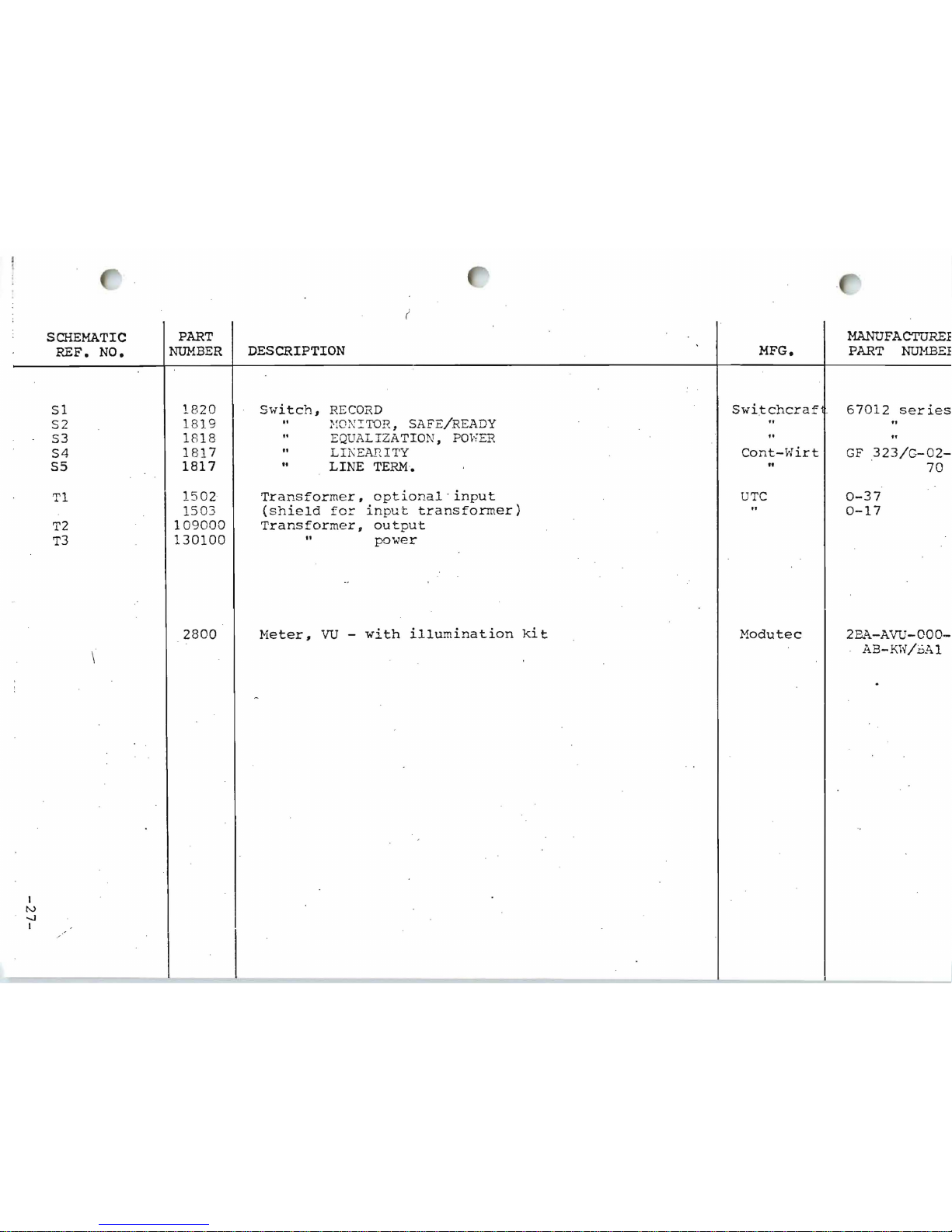
SCHEMATIC
REF.
NO.
Sl
S2
S3
PART
NUMBER
1820
18
19
1818
DESCRIPTION
Sidtch,
RECORD
"
}fON
!TOR,
SAFE/READY
..
EQUALI
ZATION,
pm";ER
MFG.
Switchcraf
..
..
MANUFACTUREE
PART
NUMBE:F
67012
series
..
"
S4
55
1
81
7
1817
to
LII\EAnITY
..
LINE
TERM
, •
Cont-Hirt
"
GF
323/G-02-
70
Tl
1502
Transformer,
optional ' input
UTC
0-37
1503
(shield
for
input
transformer)
"
0-17
T2
109000
Transforme r,
output
T3
130100
..
power
\
2800
Meter,
VU -with
illumination
kit
Modutec
2B2\-A "ifU-OOO-
AB-KH/vA1
I
N
-..J
I
--------

nT'
~ ~i'O
I
I
LJ:~
L_
l 0
~
, V
,«
C
Q.
I
IV
CD
I
c' I
-\ -
"'
+
."
1
3~
l' I)I-~--~'"
q~~
<
R:l
o
""D
~"~.
""
r
L
'T
:~
i
----,
Flel.
ZlOk
)
17
.5
YNC.
M(N.
-./VVV'
~..
.
L"
I
L~~
en
- -
.....
-...jl~
R:~?,
,,>1(
D
~!
B
!""PlJ1~
.
./
.
'II
en ,
~
D
~7I.)1ot[
MP'l
J'T
S
Vfit
AMPl,n(q
E
<)---)0
e .
:.o.;:
';'
rt
'
:oc:r,-
~"t
K
~
!S~
....
.f.
~
Q
OU
...
T
N
<Q-----')
2 0
eoA'. ...."
p
<)----")
2 '
.::'(,!
~
u..
..... '(.
i=!
-:J---------!o.
22
f:=-
~
...
~
utr.
t.
S
~
2~
:
Co..
i."
;.
0<." !),.-
T
"}--')
2 4
1
U
~2
SJ
°i/.OR.O
~\~
I.SIt
~191..
''''-S
C',;-"'r
~
4 L
.c-
.....
:~~
:.
'(
;)
.n
_ _ ,
~
,:
-~
,
.
'
:~
'
:
:
~
-
,
~.
,,
~
B
~,
]
"F
?
",,,,,,
~
- '
~
...
C.(.h , ~-:t..
----=:--
S
1 '
')
-~Y
1
'>
F
REPROOu:£. LINt
AMP
"q----
~
,
12
p ""."",
(US(~·'NsT"'L.L
rO O
PTIO~
I
[
.
"~~ I ~
:
I',
L[ f [
1-"
1
'"
_~,
N01ES:
U
!l.
l~"
1)
,lIn
l'l' '''
',(, It€I!'
FlT
( O
L
"1'
( 0
~t·
·f".H~·J.w~TT
I~.,
II o\H': N
t"~'J
z.rr
,r,.,.;lI""Il,(--"JlI"
"a.! ~'(~
t"j,
~ llU~"'
~
IIR
(
'-
"lit "
(1'0
~ l~. \)i.%'
\.\
A. 1( .. /IP (
p/""
~
5. R:S ,',
5.
(;,.
1(
w,'t
l,l
'), "'(
I'f..
'P
UHr"'''V,lll)
C 1-14,22
-34,
"
11'
2
." Y;~'IIol
IO
..
4()-4J
1.
11
M
~!)
Tl
I\I~r
PI N
1")0(1
CR 1-10
a.
nT-~
fl.f\ ( '
'I
N 12
11
IC
;-4
1 ""- 1I(1).
/'J
.-"IIt "
,.
\\.\l(.llO
ro
t:
q
(,~
l'
S:U.";,PONU ....
11""
1010\,0
\1)(,0
Q
1-11,21 -29
,
J.\.J.
"f. -:L'. 7"{
"' "0
I
4
(HI
-.
~
;3
So(.
\4[,
W\""TI
C.
R 1- 43,
n
o~
51
-69
,
RtPP
.o()1.)~
(.
2IOCIr.M.D
71-63.
. I . 1
:9
000
90-
97
E
T
1.
2

li~INIII'\jT
7 D
'Ok
1 '
= t
r--
-
E8
~
OEr
....T
Iti,C.CRO
cL""
....
1
;
'S'f~1.I",o@ IJrt".PV'T
~vj,
~u~
;.
~"<,;..,,,.,
I I
~'l"'At.~":t
I '«'UlRO "
EAIl
N
(D
21.
t.
......
c.,E.
~!..AD
tn.L'"
\..tIl,oII(.
or
.,."
""""
R!.(.090 \,V....-:
..
zo
V
NCT
ES:
3.
~
-ZO~
4':
,
5.
F[7\
~
J.O¢(O
1
~0._ :,~
"
W."
,.,
,"
--=~
e,:..a..~o
-~2"OO
U
......
t~')
(1I'"l..~'iE.
'P{t~
L
;"'l~
1:I5.~"S'
;'\~ ~
..
W, \0
1..
""lJ..IJ~
IN
CWMS
l.(~~
lJ!:!:..~
~I(
~~
:(.'!I
~L
0 /
"4
I
~
At<t
0 /
10( 1100
:..
..
( PI N
111
\
o."J
,
.,j((f~A.Q,'"
To
e.~",,,
lAA~
M£JiIO
t.I~1T
' NOuC.TANC.!.
T~
~'S_'"
lz~"t.t,)
OR
L
5"""IOllI
POI()
U.)
r
_-----i'"
-:t
I
ro,~
I
.'
~f'"';
<>T
lJ
--J:
I
Mi'"
~~
S2'3
P
II
of'
HOI
I -
r"
_"
.:'
"I
- r "
~~
--
RE' C Cl.O
.-
;-::,
1
'

.c
c,~
.
4~o,
T~~"&
"""<R
5w
6----.l
C-J
'S
...
r:":'v~;.'
p.,c
5~'------
o
c"""-"" 8
<-.
--------j-------1
n
"U
t'"
T
~
~'-R
_
~
";':
\."'R:
I I
N.:rA
(1l 4 1"
l
~
:>
~;
-
ES .
..,
....c·.· :....
...
.....
-:.
i:
"l~'t('~'~D
= ,"
O'(,
l ....
~
·:O:::~
'I
........ ',
'7
., \ l\
l '.I(
t~
:.Io4M":.
1
:.:.~;,
..
~...: ~ "'
~l"t ';) t~ M~(r.r~
rP...:::..~O'i.
!.
'C
: :
t~
0.
,,::
, ~ ..
"
1106
• R
1:
") .~
......
'.
r=-.t
110
\.0(.
'T
o;:;..
',,!~
P<j
~T
L
:',#l ':..
.! ... '
_\'>1
rc~;
..
~
:> ~ TQ.\I';,~.·.)
...
'f
~r
!,o'
1.
r
__
.
I..
i
..
e\A~
\..O. I1I.I,Q
[f)UA.'-llA"T
ION
PIoI.c.o-.·,.D
')A
..
t/Qrx~
.",-",,'
• ZOV'
OVT -2010'
o£r(~'
L"""
INT
WI(, W
£ ....... G:..i
~""'rTllol
cov.
7
21
9
19
17
IS
20
II
1
<:
l2
R..E
~O
...
18
~'"
ot.,,::>t,
11«
0,,"
1
,.~;,.
.~'
.)
.
...
I r
10
~~.lf
I~~
1))7
' ''-
t
~,;c
"
r
'00
~,,,
<".:.~:
c; I':.~.\'
l
~
",..-~
'-
'-'
Coo
" ! '
,..
1 I
.:vf\h
I:;::
,
10<
S
-;-
J I
IZIt
\'a.
-'.7
It
~~"
?"
1;
SOl
II
I
I
01
~
i
r
I
/ I
C,:
l!
l
0.,
I
"'':''''!"
~~"'
I
.
~~'5<.
'
'n,
"~
'
.i,L
~
S"~
"
D . !
".
q.
~.
2N!SLl
S2.]f-
I
'I
.n
NO"!'
~
~
'","
~
"
'0<
OO~
C2
:~Sb~
"t1
..
3 ,
')1(
~
""
I
e::.::
r~
p
<c
I
I
t"
}.
......
A I
C
II
CR
14
Ie:
I
I
o
12
R 3
J
-
l~'--
SCR
I
""
I
.~.o,(;
Y I
Jr.
..
I,_. 7 :'
!,-- i.
"'--"'Ic..
~
,:, ,,.r.
::, ~I.~_"
P.tC'
.~7';
,2J,C J
2NS2<;14.
,.----t--1C--
1:.'''''
'g,
OJ)J
l
RT
I
O~
0-;0.
R4
12. .111:
"
R'
12.10:.
'.
RO
Il.'K
10.'
11.
R'
;.'J'
"

~~~
0 £
-~~
E
a
l
:~;:~::
~
INPUT
~
. '7
Jl
l
JI
-
I
0J
T I
~TEZr-
__________
~__~
1.4
o
N
I
T
o
R
~"'N~
1
1~
-=
~---I-------
I
R~
3.6K
5"L
SS
4.7K
~
"H'"
0
(y
u
R6
.I\
I\
/\/,-
410
f>\.\ON£~
[J"
RE.MOTE
J8 1
1
12131 4 15161
7
18\
IIII!
11
1"4"
II
~
HI
1111
__
I
II
~
~
b I U I I I I I I I I I I
~II
~
CAL
BLU
- 7
8
,~
'
:::
J4
T?>
w..u.o..
rg
'Cc
"''"
'
co
":
",.,,
"
I I I I I I l O
ON
..
C I
'1'(\
..
-
I
[
E.R"''>E
".0.0
J5 ""'Y....
~-----124
RE
CORO 2S
J1
-L
~
~
11
JH I I I
~
~ ~
1m
t~
\.I.EA.t)
Av
,PI.IF't
[J\
C.c)'RC
A.,)<;.'y
NOTES:
UNL"::'':I
OT~i..R"w\U
<,:,PEtlrlEQ
I.
5='1)(£0
RP"I~TOR!Io
l£
IN
1011 vA\.UE
'N
OlolM\
2..
RI
uHD
~L"
WfT
....
O"'TION"l.
INPUT
OA.~~~O
\.INt.~
~""0'wV
Co..,NUTfat,l
WIo(£'-'I "
NOT
u~~o
l.
~lMOV[
JVM'P£"
A<"RO!l.~
R4I
F'o~
..
~e_
Llt.le.
CAuG.R",.\o
....
lRAN~~
J9
NtVTRAL
A.c.
LU
..
IL
2
PLo.."
4
.3
RECORD
\.II
EO
5
\.0
EQ
6
P/~
c.:'\A
7
SIA."
IN
8
'3
el.l).~
C).;T
C,R..C~ND
~
J
10
POWER
Tft.A"~'ORt.J\EA.lTll
~
>«(01>.0
POwm
315
c
..•
( otO
-i
~c?YR~
}E~
"-O~tOI I~~II)oOo_ c-c...~
~
S(kEMA"[I(-
375
CHASSIS
l"'I.'
O,
lI'1.:CIO!I
_ ciu !,"
i
,':',
I ·-'''~
2 9 3
00
I'
s'

INOVON
ICS
WARRANTY
Inovonics, Inc.
workman
will
days and one year
installatio
return
purcha
the user's loca
T
his war
1. Warr nty
2. Warran
3. Warr
ship.
be repa
n billed
equipment for warranty
sed
ran
to
the fact
made,
an
prod
Any disc
ired free of charge.
unless
tion
ty
is
subje
card supplied
ory
ty
is void
or
if
serial iden
ty does
ucts are
repanc
from
at normal
prior
arrangement
.
ct
to
within
if
unauthoriz
not
apply
warranted
ies
noted
Additionally
the date
the follo
10 day s
tification
of
purchase
rates.
with
to damage caused
It
service
is
wing
the
of
purch
ed
has been defaced, removed,
to
be
with
in
, parts
will
will
be
the
to
the
made
with
conditions
equipment
ase.
attempts
free
from
90
days
for
repairs required between
be
supplied free
responsibility
dealer
at repair
by
from
the
dealer
:
must
be
misuse, abuse,
defects in
of
the
of
whom
to
inspect
completed
or
modification
or
material
date
of
purchase
of
charge,
the purchaser
it
was
originally
or
repair
and
returned
have been
altered.
or
accident.
and
90
with
to
at
4. Warranty
valid
only to
original purcha ser.
 Loading...