

Page 1

User Guide
NICE900 Series
Integrated Door Operator Controller
Data code 19010269
User Guide
A02
Page 2

Preface
Preface
Thank you for purchasing the NICE900 series integrated door machine controller.
The NICE900 series integrated door machine controller (shorted as "the NICE900" or "the
controller" hereinafter) is a variable frequency controller specialized for driving the door
machine system such as elevator door, cold storage door, and subway door.
It integrates door open/close logic control and motor drive, and implements control on the
entire door system with door open/close commands from the external system. The NICE900
can drive the AC asynchronous motor and permanent synchronous motor (PMSM), and
supports two control modes, speed control and distance control. Applicable to various
applications, it can meet drive and control requirements of most door systems.
This manual describes correct use of the NICE900, including product features, safety
information and precautions, installation, parameter setting, commissioning, and
troubleshooting. Read and understand the manual before using the product, and keep it
carefully for reference to future maintenance.
Notes
•The drawings in the manual are sometimes shown without cover or protective guard. Remember
to install the cover or protective guard as specied rst, and then perform operations in
accordance with the instructions.
•The drawings in the manual are shown for description only and may not match the product that
you have purchased.
•The instructions are subject to change due to product upgrade, specication modication, as
well as the efforts to increase the accuracy and convenience of the manual.
•Contact our regional agent or customer service center if the manual delivered is lost or
damaged.
•Contact our customer service center if you have problems during the use.
•Email: UM@inovance.com
- 1 -
Page 3

Preface
Note
Approvals
Certication marks on the product nameplate indicate compliance with the corresponding certicates and
standards.
Certication Mark Directives Standard
EMC directives 2014/30/EU
CE
TUV - EN 61800-5-1
LVD directives 2014/35/EU EN 61800-5-1
RoHS directives 2011/65/EU EN 50581
EN 12015
EN 12016
UL
- UL61800-5-1
C22.2 No.14-13
● The above EMC directives are complied with only when the EMC electric installation
requirements are strictly observed.
● Machines and devices used in combination with this drive must also be CE certied and
marked. The integrator who integrates the drive with the CE mark into other devices has
the responsibility of ensuring compliance with CE standards and verifying that conditions
meet European standards.
● The installer of the drive is responsible for complying with all relevant regulations for
wiring, circuit fuse protection, earthing, accident prevention and electromagnetic (EMC
regulations). In particular fault discrimination for preventing re risk and solid earthing
practices must be adhered to for electrical safety (also for good EMC practice).
● For more information on certication, consult our distributor or sales representative.
- 2 -
Page 4

Preface
Contents
Preface ...................................................................................................................1
Chapter 1 Safety Information and Precautions.......................................................6
1.1 Safety Information ....................................................................................................... 6
1.2 Precautions ................................................................................................................. 9
Chapter 2 Product Information .............................................................................12
2.1 Designation Rules and Nameplate ............................................................................ 12
2.2 Structure .................................................................................................................... 12
2.3 NICE900 Models ....................................................................................................... 13
2.4 General Specications .............................................................................................. 13
Chapter 3 Mechanical and Electrical Installation .................................................. 16
3.1 Mechanical Installation .............................................................................................. 16
3.2 Electrical Installation .................................................................................................. 18
3.3 Peripheral Electrical Devices ..................................................................................... 20
Chapter 4 Operation and Trial Running ................................................................24
4.1 Operation Panel ........................................................................................................ 24
4.2 Basic Operations ....................................................................................................... 25
4.3 Command Source and Motor Auto-tuning ................................................................. 28
4.4 Door Open/Close Control Mode ................................................................................ 31
Chapter 5 Function Code Table ............................................................................ 42
5.1 Description of Function Codes .................................................................................. 42
5.2 Function Code Table ................................................................................................. 42
Chapter 6 Description of Function Codes.............................................................54
Group F0: Basic Parameters ........................................................................................... 54
Group F1: Motor Parameters .......................................................................................... 56
Group F2: Performance Control Parameters .................................................................. 59
Group F3: Door Open Running Curve Parameters ......................................................... 62
Group F4: Door Close Running Curve Parameters ......................................................... 65
Group F5: Door Open/Close Auxiliary Parameters ......................................................... 69
Group F6: Distance Control Parameters ......................................................................... 72
Group F7: Demonstration Function Parameters ............................................................. 76
- 3 -
Page 5

Preface
Group F8: Auxiliary Parameters ...................................................................................... 77
Group F9: Input and Output Function Parameters .......................................................... 79
Group FA: Display and Fault Parameters ........................................................................ 81
Group FP: User Parameters ............................................................................................ 87
Chapter 7 Maintenance and Troubleshooting.......................................................90
7.1 Maintenance .............................................................................................................. 90
7.2 Fault Information and Troubleshooting ...................................................................... 91
Revision History....................................................................................................96
Warranty Agreement .............................................................................................97
- 4 -
Page 6

1
Safety Information and Precautions
Page 7

Chapter 1 Safety Information and Precautions
DANGER
CAUTION
DANGER
CAUTION
DANGER
CAUTION
Chapter 1 Safety Information and Precautions
In this manual, the notices are graded based on the degree of danger:
•
indicates that severe personal injury or even death may result due to improper
operation.
•
indicates that personal injury or equipment damage may result due to improper
operation.
Read the following safety notices carefully so that you understand how to install, commission,
operate and maintain the equipment. Inovance assumes no liability or responsibility for any
injury or loss caused by improper operation of the equipment described in the manual.
1.1 Safety Information
■Before Installation
•Do not install the equipment if you nd the controller damaged upon unpacking.
•Do not install the equipment if the packing list does not conform to the product you receive.
•Handle the equipment with care during transportation. Otherwise, the equipment may be
damaged.
•Do not touch the components with your hands. Failure to comply will result in static electricity
damage.
■During Installation
•Mount the controller on incombustible surface such as metal. Keep it far away from ammable
materials. Failure to comply may result in a re.
•Do not loosen the xed screws of the components, especially the screws with red mark.
•Do not drop wire end or screw into the controller. Otherwise, the controller may be damaged.
•Install the controller in places free of vibration and direct sunlight.
- 6 -
Page 8

Chapter 1 Safety Information and Precautions
DANGER
DANGER
DANGER
DANGER
■At Wiring
•Wiring must be performed only by qualied personnel under instructions described in this
manual. Failure to comply may result in unexpected accidents.
•A circuit breaker must be used to isolate the power supply and the controller. Failure to comply
may result in a re.
•Tie the controller to ground properly according to the standard. Failure to comply may result in
electric shock.
•Never connect the power cables to the output terminals (U, V, W) of the controller. Pay attention
to the marks of the wiring terminals and ensure correct wiring. Failure to comply will result in
damage to the controller.
•Ensure that the cabling satises the EMC requirements and the local codes. Use wire sizes
recommended in the manual. Failure to comply may result in accidents.
•Use the shielded cable for the encoder, and ensure that the shield is reliably grounded at one
end.
•Use a twisted cable with twisted distance of 20−30 mm as the communication cable, and ensure
that the shield is reliably grounded.
■Before Power-On
•Check that the following requirements are met:
The voltage class of the power supply is consistent with the rated voltage class of the controller.
The input terminals (L, N) and output terminals (U, V, W) are correctly connected.
No short circuit exists in the peripheral circuit.
The wiring is secured.
Failure to comply will result in damage to the controller.
•For the PMSM, ensure that motor auto-tuning is performed before running for the rst time.
Failure to comply may result in motor runaway.
•Do not perform the voltage resistance test on any part of the controller because such test has
been done in the factory. Failure to comply will result in accidents.
•Cover the controller properly before power-on to prevent electric shock.
•All peripheral parts must be connected correctly under the instructions described in this manual.
Failure to comply may result in accidents.
- 7 -
Page 9

Chapter 1 Safety Information and Precautions
DANGER
DANGER
DANGER
CAUTION
DANGER
■After Power-On
•Do not open the cover of the controller after power-on. Failure to comply may result in electric
shock.
•Do not touch any input or output terminal of the controller with hands. Failure to comply may
result in electric shock.
•Do not touch the rotating part of the motor during the motor auto-tuning or running. Failure to
comply may result in personal injury.
•Do not change the factory parameters. Otherwise, the equipment may be damaged.
■During Running
•Do not touch the fan or the discharging resistor to check the temperature. Otherwise, you may
get burnt.
•Signal detection must be performed only by qualied personnel during operation. Failure to
comply will result in personal injury or damage to the controller.
•Avoid objects falling into the controller when it is running. Failure to comply will result in damage
to the controller.
•Do not start/stop the controller by opening or closing the contactor. Failure to comply will result
in damage to the controller.
■During Maintenance
•Do not repair or maintain the controller at power-on. Failure to comply will result in electric
shock.
•Repair or maintenance of the controller must be performed only by qualied personnel.
Otherwise, personal injury or equipment damage may result.
•Set the parameters again after the controller is replaced. All the pluggable components must
be plugged or removed only after power-off.
- 8 -
Page 10

Chapter 1 Safety Information and Precautions
Note
1.2 Precautions
1. Motor Insulation Test
Perform an insulation test on the motor under the following conditions:
- Before the motor is used for the rst time
- When the motor is reused after being stored for a long time
- During periodic inspection
This is to prevent the poor insulation of motor windings from damaging the controller.
The motor must be disconnected from the controller during the insulation test. A 500-volt
megameter is recommended for this test, and the insulation resistance must not be less
than 5 MΩ.
2. Motor Heat and Noise
The output of the controller is pulse width modulation (PWM) wave with certain harmonic
wave, and therefore, the motor temperature rise, noise, and vibration are slightly greater
than those at running with the mains frequency.
3. Voltage-sensitive device or capacitor on the output side of the controller
The controller outputs PWM waves, and therefore, do not install the capacitor for improving
power factor or lightning protection voltage-sensitive resistor on the output side of the
controller. Otherwise, the controller may suffer transient overcurrent or even be damaged.
4. Use outside the rated voltage
The controller must not be used outside the allowable voltage range specified in this
manual. Otherwise, components inside the controller may be damaged. If required, use
a corresponding voltage step-up or step-down device to match the power voltage to the
rated voltage range for the controller.
5. Surge Suppressor
The controller has a built-in varistor for suppressing the surge voltage generated when
the inductive loads (electromagnetic contactor, electromagnetic relay, solenoid valve,
electromagnetic coil and electromagnetic brake) around the controller are switched on or
off. If the inductive loads generate very high surge voltage, use a surge suppressor for the
inductive load or use a surge suppressor together with a diode.
Do not connect the surge suppressor to the output side of the controller.
6. Altitude and De-rating
In places where the altitude is above 1000 m and the cooling effect reduces due to thin air,
it is necessary to de-rate the controller. Contact Inovance for technical support.
- 9 -
Page 11

Chapter 1 Safety Information and Precautions
7. Disposal
The electrolytic capacitors in the main circuit and PCB board may explode when they are
burnt. Poisonous gas is generated when the plastic parts are burnt. Treat them as ordinary
industrial waste.
8. Adaptable Motor
- The standard adaptable motor is an adaptable four-pole squirrelcage asynchronous
induction motor and AC PMSM. Select the proper controller model according to the motor
ratings.
- To reach better control result, perform motor auto-tuning based on actual conditions. For a
PMSM, motor auto-tuning is mandatory.
- The controller might alarm or be damaged when a short circuit exists on cables or
inside the motor. Therefore, perform the insulation short circuit test when the motor and
cables are newly installed or during routine maintenance. During the test, disconnect the
controller from the tested parts
- 10 -
Page 12

2
Product Information
Page 13

Chapter 2 Product Information
NICE
A
D
S
0P2
NICE series
A
Controller
Mark Type
D
Elevator door
machine products
Mark Type
S Single-phase 220 V
Mark Voltage Class
0P2 200 W
Mark Power Rating
0P4 400 W
0P7 750 W
MODEL: NICE-D-A-S0P2-INT
INPUT: 1PH AC220-230V 2.7A 50Hz/60Hz
OUTPUT: 3PH AC0-230V 1.3A 0-99Hz 200W
Suzhou Inovance Technology Co.,Ltd.
Serial No.: 010150144C700061
Nameplate
Model
Rated input
Rated output
Serial No.
-INT
Version
Mark
-(a)
Other variants
-INT
International
Note (a): The model number may include a suffix
"XXXXXXXXXX", Where "XXXXXXXXXX" can be blank or
combination of any alphanumeric and/or symbols that
represents customer identity.
PRODUCT: Integrated Door Controller AC Drive
Product name
Certi-
ficates
Made in China
Manufacturer
Operation panel
Fan
Power switch
Reserved
Logo
Controller output terminal
Reserved
Door state
output terminal
Encoder and control
signal input terminal
Single-phase power
input terminal
Chapter 2 Product Information
2.1 Designation Rules and Nameplate
Figure 2-1 Designation rules and nameplate of the NICE900
2.2 Structure
Figure 2-2 Structure of the NICE900
- 12 -
Page 14

2.3 NICE900 Models
Table 2-1 NICE900 models
Chapter 2 Product Information
Model Input Voltage
NICE-D-A-S0P2
NICE-D-A-S0P4 1.0 5.4 2.3 400
NICE-D-A-S0P7 1.5 8.2 4.0 750
Single-phase 220 V
(-15% to 20%)
Power
Capacity
(kVA)
0.5 2.7 1.3 200
Input Current
(A)
Output
Current
(A)
2.4 General Specications
Item Specications
Maximum
output
frequency
Speed range
Basic
specications
Major functions
Protection functions
Speed stability
Startup torque
Frequency
resolution
Current
resolution
Carrier
frequency
99.00 Hz
1:50 (SVC)
1:1000 (CLVC)
SVC: sensorless vector control
CLVC: closed-loop vector control
±0.5% (SVC)
±0.05% (CLVC)
1 Hz/150% (SVC)
0 Hz/180% (CLVC)
0.01 Hz
0.01 A
2–16 kHz
Two auto-tuning modes are supported, with-load auto-tuning and
no-load auto-tuning.
For CLVC on the AC PMSM using a common ABZ encoder, opencollector output or push-pull output is supported.
For SVC, functions such as xed torque boost, customized torque
boost and over-excitation are supported.
Door width auto-tuning is supported.
Automatic demonstration is supported.
Automatic identication upon hindering is supported.
Controller overload protection (1 minute for 150% of rated current
, 1 second for 180% of rated current) is supported.
Protections on overvoltage, undervoltage, overcurrent, output
phase loss and inter-phase short circuit are supported.
Adaptable
Motor
(W)
- 13 -
Page 15

Chapter 2 Product Information
Item Specications
Indoors
Free from direct sunlight, dust, corrosive gas, combustible gas, oil
mist, vapor, drip and salt
Lower than 1000 m
Deratedif the altitude is above 1000 m
-10°C to +40°C
Derated if ambient temperature is within 45–50°C
-20°C to +60°C
Natural cooling for 0.2 kW
Forced air cooling for 0.4 kW and 0.75 kW
IP20
Indoors, clean and dry
Packed in standard box and transported by coach, train, aircraft
or ship.
15 m/s2 (1.5 g) when SIN vibration is 9–200 Hz
Environment
Installation
location
Altitude
Ambient
temperature
Humidity Less than 95% RH, non-condensing
Vibration < 5.9 m/s2 (0.6 g)
Storage
temperature
Cooling method
Ingress
protection
Storage
location
Transportation
Vibration during
transportation
- 14 -
Page 16

3
Mechanical and Electrical Installation
Page 17

Chapter 3 Mechanical and Electrical Installation
204.7
213.7
5
φ
4
-
66
Unit: mm
129
147
Hot air
Cold air
≥ 100
≥ 100
50≥
50≥
Chapter 3 Mechanical and Electrical Installation
3.1 Mechanical Installation
3.1.1 Installation Environment
Item Requirement
Ambient temperature -10°C to 50°C
Mount the controller on the surface of incombustible objects with
Heat dissipation
Mounting location
3.1.2 Physical Dimensions
Figure 3-1 Physical Dimensions of the NICE900
sufcient room for heat dissipation.
Install the controller on the base with screws vertically.
Free from direct sunlight, high humidity and condensation
Free from corrosive, explosive and combustible gas
Free from oil dirt, dust and metal powder
3.1.3 Mounting Clearance
The clearance that needs to be reserved varies with the power rating of the NICE900. The
following gure shows the clearance that needs to be reserved for mounting.
Figure 3-2 Clearance around the NICE900 for mounting
- 16 -
Page 18
Chapter 3 Mechanical and Electrical Installation
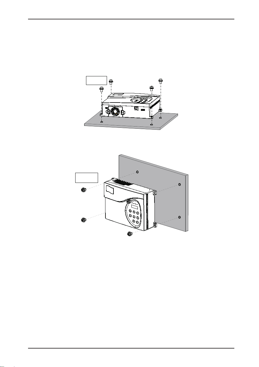
Fix the four
screws
Fix the four
screws
3.1.4 Mounting Orientation
Use 4 M4x15 screws (with elastic at washer) with the tightening torque of 1.2 N.m during
installation.
a) Horizontal installation
Figure 3-3 Horizontal installation diagram
b) Vertical installation
Figure 3-4 Vertical installation diagram
- 17 -
Page 19

Chapter 3 Mechanical and Electrical Installation
Single-phase
power input terminals
Reserved
Controller
output terminals
U
V
W
N/A
L
N
220 VAC
L N
Ground
P
PB
U
V W
L N
NICE900
Regen. resistor
(Terminal reserved)
3.2 Electrical Installation
3.2.1 Wiring and Description of Main Circuit Terminals
Figure 3-5 Main circuit terminal arrangement
Table 3-1 Main circuit terminal description
Terminal Name Description
Single-phase power input
L, N
terminals
P, PB Reserved
U, V, W Controller output terminals Connect the three-phase motor.
Grounding terminal Must be grounded.
Provide single-phase 220 VAC power supply.
These terminal are generally reserved, but they can be
connected with the external regen. resistor if required.
Figure 3-6 Main circuit wiring example
In the applications with large inertia such as the cold storage door, a regen. resistor is required.
Select a proper one according to the recommended models listed in the following table.
- 18 -
Page 20

Chapter 3 Mechanical and Electrical Installation
Reserved
Encoder and control
signal input terminal
TA
1
TC1
TB1
TA2
TB2
TC
2
TA3
TC3
TB
3
Door state
output terminal
+24V
PGA
PGB
PGZ
COM
DI1
DI
2
DI3
DI4
DI5
DI6
DI7
DI8
COM
+24V
COM
Table 3-2 Recommended regen. resistor models
Controller Model Power of Regen. Resistor (W) Resistance of Regen. Resistor (Ω)
NICE-D-A-S0P2 80 W ≥ 250 Ω
NICE-D-A-SOP4 80 W ≥ 200 Ω
NICE-D-A-SOP7 80 W ≥ 150 Ω
3.2.2 Wiring and Description of Control Circuit Terminals
Figure 3-7 Control circuit terminal arrangement
Table 3-3 Control circuit terminal description
Name Type Mark
Door state
output terminal
Relay output
and grounding
TA1/TB1/TC1
TA2/TB2/TC2
TA3/TB3/TC3
Relay output
- 19 -
Function
Description
Remarks
1. TA-TB: normally closed (NC)
TA-TC: normally open (NO)
Contact capacity:
250 ACV, 3A; 30 VDC, 1 A
2. Insulation voltage class
between contact and control
circuit: 2.5 kVAC
Page 21

Chapter 3 Mechanical and Electrical Installation
Name Type Mark
Internal 24 V
power supply
Encoder and
control signal
input terminal
Encoder input
Digital input DI1 to DI8 Digital signal input
Reserved
Software
burning
interface
+24V
COM
PGA Encoder phase A
PGB Encoder phase B
PGZ Encoder phase Z
RJ45
Function
Description
24 VDC power
supply
24 V power
common
Software burning
interface
Remarks
Used as the non-contact
switch or power supply for the
encoder.
Maximum output current: 200
mA
Isolated with the internal 24 V
power common terminal of the
controller
Open-collector output or pushpull output
Optocoupler isolation, low level
active
Input voltage range: 0–30 VDC
Input impedance: 3.3 kΩ
-
Check the peripheral wiring before power-on to ensure device and personal safety:
1. The wiring is performed according to the instructions.
2. All switches act reliably.
3. Check the inter-phase resistance of the main circuit to ensure that there is no short circuit
to ground.
4. The mechanical installation is proper.
5. Check that the resistance between the following points and the ground is close to innity.
- L, N and PE
- U, V, W and PE
- Encoder 24V, PGA, PGB, PGZ, COM and PE
3.3 Peripheral Electrical Devices
3.3.1 Selection of Peripheral Electrical Devices
Controller Model Air Switch (A) Contactor (A) Main Circuit Conducting Cable (mm2)
NICE-D-A-S0P2 10 10 2.5
NICE-D-A-S0P4 16 10 2.5
NICE-D-A-S0P7 16 10 2.5
- 20 -
Page 22

Chapter 3 Mechanical and Electrical Installation
3.3.2 Description of Peripheral Electrical Devices
Electrical Device Mounting Location Function Description
Air switch Power input side
AC input reactor Controller input side
AC output
reactor
Between the controller
output side and the motor,
close to the controller
It is used to cut off the controller’s power supply
and provide short circuit protection.
•Improve the power factor of the input side.
•Eliminate the higher harmonics of the input side
effectively,
•Protect the rectier bridge effectively.
•Eliminate the input current unbalance caused by
inter-phase unbalance.
If the controller is more than 100 m far away from
the motor, install the AC output reactor.
- 21 -
Page 23

Chapter 3 Mechanical and Electrical Installation
- 22 -
Page 24

4
Operation and Trial Running
Page 25

Chapter 4 Operation and Trial Running
CLOSE
STOP
RES
PRG ENTER
OPEN
D1 D2 D3 D4
Data display
Function indicator
Programming key
UP key
Down key
Confirm key
Shift key
Door open key Door close key
Stop/Reset key
PRG
ENTER
STOP
RES
Chapter 4 Operation and Trial Running
4.1 Operation Panel
You can modify the parameters, monitor the working status and run or stop the controller by
operating the operation panel shown as below:
Figure 4-1 Operation panel diagram
1. Indicator Descriptions
Table 4-1 Indicator descriptions
Indicator
Speed Control Distance Control
Meaning of ON at Stop
D1 DI1 signal active DI1 signal active External door close command
D2 DI2 signal active Phase A and B signal correct During door close
D3 DI3 signal active Phase Z signal active During door open
D4 DI4 signal active DI4 signal active External door open command
2. Description of Keys on the Operation Panel
Table 4-2 Description of keys on the operation panel
Key Name Function
Programming Enter or exit Level I menu.
Conrm
Stop/Reset
Enter the menu interfaces level by level, and conrm the parameter
setting.
Stop the running in the running state and reset the operation in the
fault state.
Meaning of ON During Running
- 24 -
Page 26

Chapter 4 Operation and Trial Running
OPEN
CLOSE
F0
F003
24.00
(Select the function
code group)
(Select the
function code)
(Set the value of
the function code)
Level-I menu
Level-II menu
Level-III menu
PRG
PRG
Not to save
the setting
ENTER
To save
the setting
ENTER
15.00
ENTER
Status parameter
PRG
F004
ENTER
PRG
Next function
code
(default display)
If there is a blinking digit, press
/ / to modify the digit.
PRG
ENTER
ENTER
PRG
Key Name Function
Shift
Select the displayed parameters in turn in the stop or running state,
and select the digit to be modied when modifying parameters.
Up Increase data or function code.
Down Decrease data or function code.
Door open Open the door in the operation panel operation mode.
Door close Close the door in the operation panel operation mode.
4.2 Basic Operations
4.2.1 Operation Procedure of the Operation Panel
The operation panel of the NICE900 adopts three-level menu, convenient for quick querying
and modication of parameters.
The three-level menu consists of function code group (Level I), function code (Level II), and
function code setting value (level III), as shown in the following gure.
Figure 4-2 Operation procedure on the operation panel
You can return to Level II from Level III by pressing
•After you press
, the system saves parameter setting first, and then goes back to
or
Level II and shifts to the next function code.
•After you press
Level II and remains at the current function code.
Here is an example of changing the value of F0-04 to 15.00 Hz.
, the system does not save parameter setting, but directly returns to
- 25 -
.
Page 27

Chapter 4 Operation and Trial Running
F015.00
PRG
F000
00.00
PRG
PRG
ENTER
ENTER
ENTER
PRG
F005
15.00
F004
Status parameter
(default display)
To save the
setting
If there is a blinking digit,
press / / to modify the digit.
F0
15.00
PRG
FA00
00.00
PRG
PRG
ENTER
ENTER
ENTER
PRG
FA03
FA02
FA
Status parameter
(default display)
If there is a blinking digit,
press / / to modify the digit.
Figure 4-3 Example of editing function code
In Level III menu, if the parameter has no blinking digit, it means that the parameter cannot be
modied. This may be because:
•Such a function code is only readable, such as actually detected parameter and running
record parameter.
•Such a function code cannot be modied in the running state and can only be changed at
stop.
4.2.2 Viewing Fault Information
When a fault occurs on the controller, the operation panel displays the fault code, based on
which, you can nd the cause of the fault and rectify the fault quickly.
The controller saves the last four fault codes, and details of the frequency, current, bus voltage
and DI/DO status at the latest fault are recorded.
Figure 4-4 Viewing fault information
- 26 -
Page 28

Chapter 4 Operation and Trial Running
Shift between parameters
displayed in running state
Running frequency
Bus voltage
Output voltage
Output current
Output torque
Door position pulse
Output terminal state
Frequency reference
Input terminal state
Shift between parameters
displayed in stop state
Door position pulse
Output terminal state
Frequency reference
for door open
Input terminal state
Frequency reference
for door close
F015.00
PRG
FP
PRG
FP00
0000
PRG
PRG
ENTER
ENTER
ENTER
PRG
FP01
1234
Status parameter
(default display)
If there is a blinking digit,
press / / to modify the digit.
4.2.3 Viewing Display at Running or Stop
In the stop/running state without fault, you can view the parameters circularly by pressing .
The parameters to be displayed are set in by setting FA-00 and FA-01.
Figure 4-5 Shift between parameters displayed in the running/stop state
4.2.4 Setting the Password
To protect the parameters more effectively, the NICE900 provides the user password
protection function. To cancel the password protection function, enter the password and set
FP-00 to 0.
The following gure shows an example of changing the password to 1234.
Figure 4-6 Changing the password
- 27 -
Page 29

Chapter 4 Operation and Trial Running
OPEN
CLOSE
STOP
RES
OPEN
CLOSE
STOP
RES
4.3 Command Source and Motor Auto-tuning
4.3.1 Command Source
The NICE900 supports four command sources, as described in the following table.
Function
Code
F0-02
Value Description
Operation panel control
It is mainly used in motor auto-tuning. The door machine runs at the
frequency set in F0-04.
0
(Default)
You can control door open or close by pressing
door machine by pressing
on the operation panel.
Door machine terminal control
1
Door open and close commands are input via DI terminal.
It is used in normal running state.
Door machine manual control
It is used in door width auto-tuning, during which the door machine
2
accelerates and decelerates.
The running and stop of the door machine are controlled by using the
operation panel.
Door machine auto demonstration
It is used in the door machine demonstration and trial running in the factory.
After door width auto-tuning is completed in distance control or peripheral
signals are connected properly in speed control, set the door machine auto
demonstration mode to start automatic running of the door machine.
3
Start demonstration by pressing
pressing
on the operation panel.
or
The demonstration time interval and times are set in group F7 parameters.
or
, and stop the
, and stop demonstration by
- 28 -
Page 30

Chapter 4 Operation and Trial Running
F905
.
1
2
.
.
RUN
command
Terminal
Function
Code
Value
Terminal
control
DI5
DI6
DI7
DI8
COM
Door open
Command
source
Door open
command
Door close
F906
F907
F908
F0-02 = 1
Control
system
Door close
command
■Door machine manual control (F0-02 = 1)
In this mode, the door open/close commands are given by DI terminal.
You can allocate the DI terminals with relevant signals in F9-01 to F9-08.
For example, connect the door open and close signals respectively to DI5 and DI6, as shown
in the following gure.
Figure 4-7 Door open/close control by DI terminal
4.3.2 Motor Auto-tuning
The following part takes the PMSM as an example to describe motor auto-tuning.
Follow the precautions for motor auto-tuning:
•The magnetic pole position must be identified before first-time running of the PMSM.
Otherwise, the PMSM cannot be used properly.
•After you change motor wiring or encoder wiring, or replace the encoder, the encoder
position angle must be identied again. Ensure that the magnetic position is consistent
with motor wiring during normal running.
•The motor rotates during auto-tuning. Ensure safety before starting motor auto-tuning.
- 29 -
Page 31

Chapter 4 Operation and Trial Running
F0-02 = 0 (Operation panel control)
F1-00 = 1 (PMSM)
Set F1-01
, F1
-02, F1-
03, F1-04,
and F1-05 according to motor
nameplate,
and set F2-14
Press ENTER. After "TUNE" is displayed,
press "OPEN" to start motor auto-tuning.
Perform trial running:
F0-04 = 5.00 Hz.
Press
"OPEN"
or "CLOSE" to
start trial running.
Restore the terminal control mode
(F0-02 = 1).
Connect the load.
F1-16 = 3
Disconnect the load
F1-16 = 4
Close the door properly
No-load
auto-tuning
Select
auto-tuning mode
Whether
Motor running and controller
output current are
normal?
End
Yes
No
With-load
auto-tuning
Check the mechanical part and
encoder signals
OPEN
CLOSE
Figure 4-8 Motor auto-tuning owchart (PMSM)
More descriptions about motor auto-tuning are as follows:
1. Before starting motor auto-tuning, ensure that the encoder signals are normal. If the door
closes and motor locked-rotor occurs after you start auto-tuning, it indicates that the motor
running direction is abnormal. You need to change the motor wiring or encoder wiring.
2. During no-load auto-tuning, the controller executes the forward or reverse running
command, and runs in the opposite direction after a period of time.
After several cycles of forward and reverse running, the controller calculates all parameters
and completes no-load auto-tuning. If Er20 is reported during auto-tuning, replace any two
of UVW phases and perform motor auto-tuning again.
3. During with-load auto-tuning, ensure that the door is fully closed. Press
motor slowly open the door at 25% of the rated speed and press
close the door after the door opens to a certain distance.
After three times of such operations, the controller calculates all parameters and completes
with-load auto-tuning.
4. During with-load auto-tuning, if the motor does not run or the running direction is
inconsistent with the actual door open/close command, it indicates that motor wiring is
- 30 -
to make the
to make the motor
Page 32

Chapter 4 Operation and Trial Running
Door open Door open
Door open limit
Door open slow-down
Door close limit
Door close slow-down
incorrect. You need to replace any two of UVW phases and perform motor auto-tuning
again.
5. The identied encoder zero position angle is viewed or modied in F1-14. This parameter
must not be modified after motor auto-tuning; otherwise, the controller may not run
properly.
This parameter obtained through with-load auto-tuning is not so accurate as that obtained
through no-load auto-tuning. Perform no-load auto-tuning if conditions are allowed.
6. If Er19 is reported during identication of the encoder zero position angle, check whether
encoder wiring is correct.
4.4 Door Open/Close Control Mode
The NICE900 supports two door open/close control modes, speed control and distance
control.
In speed control, the controller instructs deceleration at slow-down point and judge door open/
close limit based on the door open/close limit signal.
In distance control, the controller needs to identify the door width pulses correctly, and instructs
deceleration and judge door open/close limit based on the door open/close curve.
4.4.1 Speed Control Mode
1. Four travel switches need to be installed on the door for this mode. The controller
decelerates at the slow-down point and judges door open/close limit based on the door open/
close limit signal.
The following gure shows the installation positions of relevant signals (travel switch) of the
door machine system in speed control mode.
Figure 4-9 Installation position of signals of the door machine system
- 31 -
Page 33

Chapter 4 Operation and Trial Running
Door close
limit signal
Single
-
phase
220
VAC
power supply
M
Door motor
COM
DI1
DI2
DI3
DI4
Door close
slow-
down signal
Input common
U
V
W
L
N
TA
1
TC1
TB
1
TA3
TC3
TB
3
NICE900
Main circuit
Control circuit
Door open
slow-
down signal
Door open
limit signal
DI5
DI6
Door close input signal
Door open input signal
F9-01 = 13
F9-02
= 15
F
9-03 = 14
F9-04 = 12
F9-05 = 1
F
9-06
= 2
F9-09 =
2
F9-11 = 1
X5
Door close
limit
P24
X3
Door open
limit
B1
B
2
BM
Door open output
Door close output
Output common
Input
common
Function
code setting
Car top
board
MCTC-CTB
DI7
DI8
2. Check wiring of the door open/close signals for speed control.
The following gure takes Inovance elevator control system to describe wiring of the relevant
signals.
Figure 4-10 Typical system wiring for speed control
3. Related parameter setting
Function Code Parameter Name Value
F0-01 Door open/close control mode 0: Speed control
F0-02 Command source selection 1: Door machine terminal control
F9-01 DI1 function selection 13: Door close limit signal NO
F9-02 DI2 function selection 15: Door close slow-down point signal NO
F9-03 DI3 function selection 14: Door open slow-down point signal NO
F9-04 DI4 function selection 12: Door open limit signal NO
F9-05 DI5 function selection 1: Door open command
F9-06 DI6 function selection 2: Door close command
- 32 -
Page 34

Chapter 4 Operation and Trial Running
Door open command
ON
ON
ON
OFF
OFF
OFF
Door open
slow-down signal
Door open limit signal
Frequency
Time
F3-03
F3-00
F3-05
Door close command
ON
ON
ON
OFF
OFF
OFF
Door close
slow-down signal
Door close limit signal
Frequency
Time
F4-03
F4-00
F4-05
F4-09
F4-07
4. Door open/close running curve in speed control
Figure 4-11 Door open running curve in speed control
When the door open command is active, the door machine accelerates to the speed set in
F3-00. After the low speed door open time reaches the setting of F3-02, the door machine
accelerates to normal speed set in F3-03.
After the door open slow-down signal is active, the door machine decelerates to the speed
set in F3-05. After the door open limit signal is active, the door machine enters the door open
holding state with the holding torque set in F3-08.
Figure 4-12 Door close running curve in speed control
When the door close command is active, the door machine accelerates to the speed set in
F4-00. When the low speed door close time reaches the setting of F4-02, the door machine
accelerates to normal speed set in F4-03.
When the door close slow-down signal is active, the door machine decelerates to the speed
set in F4-05. When the door close limit signal is active, the door machine enters the door close
holding state:
•Holding speed: F4-07
•Holding time: F4-08
•Holding torque: F4-12
•Door vane retraction speed and time: F4-09 and F4-10
- 33 -
Page 35

Chapter 4 Operation and Trial Running
Single
-phase
220
VAC
power supply
COM
DI
1
DI2
DI
3
DI4
Input common
U
V
W
L
N
TA
1
TC
1
TB1
TA
3
TC
3
TB
3
NICE
900
Main circuit
Control circuit
DI
5
DI6
DI7
DI8
Door close
input signal
Door open
input signal
F9-05 = 1
F9-06 = 2
F9-09 = 2
F9-11 = 1
X5
Door close
limit
P24
X
3
Door open
limit
B1
B2
BM
Door open output
Door close output
Output common
Input
common
M
Door motor
Encoder
+24
V
COM
PGA
PGB
PGZ
Shield
grounded
Car top
board
MCTC-
CTB
Function
code setting
4.4.2 Distance Control Mode
1. The encoder needs to be installed for this mode. The controller judges the door position
based on the encoder signals. The door width pulses need to be identied at rst-time running.
The controller decelerates and judges door open/close limit based on the door open/close
curve.
The following gure takes Inovance elevator control system to describe wiring of the relevant
signals.
Figure 4-13 Typical system wiring for distance control
2. Check the encoder.
The pulse signal from the encoder is critical to accurate control of the system. Before
commissioning, check the following items carefully:
1) The encoder is installed reliably with correct wiring.
2) The signal cable and strong-current circuit of the encoder are laid in different ducts to
prevent interference.
3) The encoder cable is preferably directly connected to the controller. If the cable is not long
enough and an extension cable is required, the extension cable must be a shielded cable
and preferably welded to the original encoder cable by using the soldering iron.
- 34 -
Page 36

Chapter 4 Operation and Trial Running
F0-02 = 2 (Door machine manual control)
Set F6-00 = 1 to enable door width autotuning.
Press "OPEN" or "CLOSE" to start door
width auto-tuning.
The controller closes the door at the
frequency set in F6-01
Check that door
open/close is unhindered
End
The controller opens the door at door
close limit and closes the door again at
door open limit
After door close limit, the controller stores
the data obtained in F6
-02 and F6-03.
Door width = F6-02 + F6-03 x 10000
Set door open/close limit according to
system configuration (ship if not required)
4) The shield of the encoder cable is grounded on the end connected to the controller (only
one end is grounded to prevent interference).
3. Related parameter setting
Function Code Parameter Name Value
F0-01 Door open/close control mode 1: Distance control
F0-02 Command source selection 1: Door machine terminal control
F9-05 DI5 function selection 1: Door open command
F9-06 DI6 function selection 2: Door close command
4. Door width auto-tuning
Door width auto-tuning is required before running in distance control. During door open/close,
the controller records the pulses of door movement in real time, and judges door open/close
limit based on the door width pulses.
Pay attentions to the following precautions:
•Before performing door width auto-tuning in distance control for asynchronous motor,
check that the AB phase cables of the encoder are connected correctly.
•During door width auto-tuning, the door acting direction changes automatically; guarantee
personal safety before starting the operation.
•Check that there is no obstacle in the running track of the door before starting door width
auto-tuning. If the door is hindered by an obstacle, the controller considers that door open/
close limit is reached, resulting in incorrect auto-tuning data.
The following gure shows the door width auto-tuning owchart.
Figure 4-14 Door width auto-tuning owchart
- 35 -
Page 37

Chapter 4 Operation and Trial Running
Door open command
ON
ON
ON
OFF
OFF
OFF
Door open
slow-down pulse
Door open limit pulse
Frequency
Time
F3-03
F3-00
F3-05
F6-06 x door width
F6-05 x door width
F6-04 x door width
Door close command
ON
ON
ON
OFF
OFF
OFF
Door close
slow-down pulse
Door close limit pulse
Frequency
Time
F4-03
F4-00
F4-05
F6-09 x door width
F6-08 x door width
F4-09
F6-07 x door width
F4-07
5. Door open/close running curve in distance control mode
Figure 4-15 Door open running curve in distance control mode
When the door open command is active, the door machine accelerates to the speed set in F3-
00.
When the door open position reaches (F6-04 x door width), the door machine accelerates to
the speed set in F3-03.
When the door open position reaches (F6-05 x door width), the door machine enters the
deceleration and creeping state with the speed set in F3-05 and deceleration time set in F3-
06.
When the door open position reaches (F6-06 x door width), the door machine continues low
speed creeping, and then enters the door open holding state, with the holding torque set in F3-
08. The door position is reset to 100%.
After the door open command is cancelled, the torque holding state ends.
Figure 4-16 Door close running curve in distance control mode
When the door close command is active, the door machine accelerates to the speed set in F4-
00.
When the door close position reaches (F6-07 x door width), the door machine accelerates to
the speed set in F4-03.
When the door close position reaches (F6-08 x door width), the door machine decelerates to
the speed set in F4-05.
- 36 -
Page 38

Chapter 4 Operation and Trial Running
Door open
slow-down signal
Door open limit signal
Time
Door close command
Door open command
Frequency
F4
-00
F
3-05
F4-03
F3-03
F5-00 (Abnormality
deceleration time)
0
F3-00
When the door close position reaches (F6-09 x door width), the door machine decelerates
again to the speed set in F4-07. It is recommended that F6-09 ≥ 96.0%; reduce F6-09 if there
is pulse loss during door open/close.
Set the threshold for retracting the door vane in F6-20. After the door vane is retracted and
door limit is reached, the door machine enters the torque holding state, with the speed set in
F4-07 and holding torque set in F4-12. The door position is reset to 0.
After the door close command is cancelled, the torque holding state ends.
4.4.3 Door Close Hindered
Door close hindered means that one of the following conditions occur during door close:
•Light curtain/safety edge signal active
•Output torque larger than the door close hindered torque
•Door open command active
If door close hindered occurs, the NICE900 processes this abnormality in two ways: decelerate
to stop or re-open the door, selected in F4-14. This abnormality is judged based on the time or
torque.
1. Running curve of door open command active during door close in speed control mode
Figure 4-17 Running curve of door open command active during door close in speed control
mode
After the time reaches the deceleration time in F5-00, the controller re-opens the door at low
speed, and enters normal speed running state after the time set in F3-02.
After the door open slow-down signal is active, the controller enters the low speed running
state and opens the door to the open limit position, and then outputs the door open limit signal.
- 37 -
Page 39

Chapter 4 Operation and Trial Running
Running
frequency (Hz)
Hinder torque
(%)
F4-18 F4-17
F4-20
F4-19
V2 V1
T2
T1
Curve 1
2. Related parameter setting
Function
Code
F4-14
F4-15
F4-17
F4-18
Parameter
Name
Working mode
upon door
close hindered
Door close
hindered
judging time
Normal speed
at door close
hindered
Low speed
at door close
hindered
Setting Description
F4-14 = 2
Upon door close hindered, the controller stops
immediately, outputs the door close hindered signal,
and does not respond to the door close command
within 10s. However, if the controller receives the door
0: Reserved
1: Output door
close hindered
signal
2: Immediate
stop
3: Door reopen
close or RUN (door open/close) cancellation command
within the time, it executes door close immediately
rather than restricted by the 10s time counting.
F4-14 = 3
The controller re-opens the door upon door close
hindered, and does not respond to the external door
open/close commands during door re-open.
Door close hindered occurs on one of the following
conditions during door close:
•The light curtain/safety edge signal is active.
•The output torque is larger than the door close
hindered torque.
•The door close time exceeds the value of F5-02.
It is used to set the lter time when door close is
0–9999 ms
hindered. If it is set to 0, door close hindered is not
detected.
F4-18 to F1-04
12.00 Hz
0.00 Hz to F104
2.00 Hz
F4-19
F4-20
F5-00
Normal speed
torque
Low speed
torque
Abnormality
deceleration
time
0.00–150.0%
100.0%
0.00–150.0%
100.0%
0.1–5.0s
F4-17 to F4-20 are used to judge door close hindered.
Set them according to the requirement:
V1 (F4-17) ≥ V2 (F4-18), T1 (F4-19) ≤ T2 (F4-20)
The torque threshold for judging door close hindered
is curve 1 shown in the gure. The shadow part shows
that door close hindered occurs.
It is used to set the time for the system to decelerate
from the door close speed to 0 when door close is
hindered. Set this parameter to the minimum value
as possible when ensuring that over-current does not
occur during deceleration.
- 38 -
Page 40

Chapter 4 Operation and Trial Running
Function
Code
F5-02
Parameter
Name
Door close
time limit
Setting Description
It is used to limit the door close time. If the controller
does not receive the door close limit signal within the
0–9999s
time, it determines that door close is hindered, and
performs door re-open or zero speed holding based on
the setting of F4-14.
This parameter is invalid when it is set to 0.
- 39 -
Page 41

Chapter 4 Operation and Trial Running
- 40 -
Page 42

5
Function Code Table
Page 43

Chapter 5 Function Code Table
PRG
Chapter 5 Function Code Table
5.1 Description of Function Codes
The NICE900 series door machine controller has a total of 13 groups of function codes,
namely, F0 to F9, FA, FF and FP. FX–YZ in this manual indicates the function code whose
function code group is "X" and whose function code is "YZ". For example, F3-02 indicates
function code "2" in group F3.
To facilitate the setting of the function codes, the operation panel adopts three-level menu.
The function code group is Level-I menu, function code is Level-II menu, and the setting value
corresponds to Level-III menu.
The meaning of each column in the function code table is as follows:
Function Code Indicates the function code number.
Parameter Name Indicates the parameter name of the function code.
Setting Range Indicates the setting range of the parameter.
Default Indicates the default setting of the parameter at factory.
Unit Indicates the measurement unit of the parameter.
Property
Indicates whether the parameter can be modied (including the modication
conditions)
The symbols in the function code table are described as follows:
"☆": The parameter can be modied when the NICE900 is in either stop or running state.
"★": The parameter cannot be modied when the NICE900 is in the running state.
"●": The parameter is the actually measured value and cannot be modied.
"*": The parameter is factory parameter and can be set only by the manufacturer.
The system automatically restricts the modication property of all parameters to prevent mal-
function.
"Default Value" indicates the value after parameter update when you restore factory settings,
but the actually detected parameter values or recorded values are not updated.
To protect the parameters more effectively, the NICE900 provides the password protection.
5.2 Function Code Table
After pressing
corresponding to the following function code groups:
key and then or key, the Level-I menu is displayed,
- 42 -
Page 44

Chapter 5 Function Code Table
Group F0: Basic Parameters Group F7: Distance Control Parameters
Group F1: Motor Parameters Group F8: Auxiliary Parameters
Group F2: Performance Control Parameters
Group F3: Door Open Running Curve Parameters Group FA: Display and Fault Parameters
Group F4: Door Close Running Curve Parameters Group FF: Factory Parameters (Reserved)
Group F5: Door Open/Close Auxiliary Parameters Group FP: User Parameters
Group F6: Distance Control Parameters
Group F9: Input and Output Function
Parameters
Function
Code
F0-00 Control mode
F0-01
F0-02 Command source selection
F0-04
F0-05 Input signal quick setting 0–2 1 1
F0-06 Speed at low speed running 0.00 to F1-04 4.00 Hz
F0-07 Carrier frequency 2.0–16.0 kHz 8.0 kHz 0.1 kHz
F1-00 Motor type
F1-01 Rated motor power 0–750 W 1 1
F1-02 Rated motor voltage 0–250 V
F1-03 Rated motor current 0.001–9.900 A 100 V 1 V
F1-04 Rated motor frequency 1.00–99.00 Hz
F1-05 Rated motor speed 0–9999 RPM 24.00 Hz
Parameter Name Setting Range Default
Group F0: Basic Parameters
0: Sensorless vector control
(SVC)
1: Closed-loop vector control
(CLVC)
Door open/close mode
selection
Running frequency under
operation panel control
0: Speed control
1: Distance control
0: Operation panel control
1: Door machine terminal
control
2: Door machine manual
control
3: Door machine auto
demonstration
0.00 to F1-04 5.00 Hz
Group F1: Motor Parameters
0: Asynchronous motor
1: PMSM
8.0 kHz 0.1 kHz
Model
dependent
Model
dependent
Min.
Unit
1 1
1 1
0 1
0.01
0.01
1 V
0.001 A
0.01
Hz
Hz
Hz
Property
★
★
★
☆
★
☆
☆
★
★
★
★
★
★
- 43 -
Page 45

Chapter 5 Function Code Table
Function
Code
F1-06
F1-07
F1-08
F1-09
F1-10
F1-11 Shaft D inductance of PMSM 0.0–999.9 mH
F1-12 Shaft Q inductance of PMSM 0.0–999.9 mH
F1-13 Back EMF of PMSM 0–250
F1-14
F1-15 Real-time angle of PMSM 0.0–359.9°
F1-16 Motor auto-tuning mode
F2-00
F2-01 Speed loop integral time 1 0.01–10.00s 1.00s 0.01s
F2-02 Switchover frequency 1 0.00 to F2-05 5.00 Hz
F2-03
F2-04 Speed loop integral time 2 0.01–10.00s 1.00s 0.01s
F2-05 Switchover frequency 2 F2-02 to F1-04 30 1
F2-06
F2-07 Current loop integral gain 10–500 50 1
Parameter Name Setting Range Default
Stator phase resistance of
PMSM
Rotor phase resistance of
asynchronous motor
Leakage inductance of
asynchronous motor
Mutual inductance of
asynchronous motor
Magnetizing current of
asynchronous motor
Encoder zero position angle
of PMSM
Group F2: Performance Control Parameters
Speed loop proportional gain
1
Speed loop proportional gain
2
Current loop proportional
gain
0.00–99.99 Ω
0.00–99.99 Ω
0.0–99.99 mH
0–999.9 mH
0.001–9.900 A
0.0–359.9°
0: No auto-tuning
1: Static auto-tuning for
asynchronous motor
2: Complete auto-tuning for
asynchronous motor
3: No-load auto-tuning for
PMSM
4: With-load auto-tuning for
PMSM
0–100 15 1
0–100 15 1
10–500 120 1
Model
dependent
Model
dependent
Model
dependent
Model
dependent
Model
dependent
Model
dependent
Model
dependent
Model
dependent
Model
dependent
Model
dependent
0 1
0.01 Ω
0.01 Ω
0.1 mH
0.001 A
0.1 mH
0.1 mH
Min.
Unit
0.01
mH
1
0.1°
0.1°
0.01
Hz
Property
★
★
★
★
★
★
★
★
★
●
★
☆
☆
☆
☆
☆
☆
☆
☆
- 44 -
Page 46

Chapter 5 Function Code Table
Function
Code
F2-08 Slip compensation coefcient 50%–200% 100% 1%
F2-09 Inertia compensation 0–9999 0 1
F2-10 Torque boost 0.0%–30.0% 8.0% 0.1%
F2-11 Over-excitation gain 0–200 64 1
F2-12 Initial position judging method
F2-13 Feedback speed lter level 0–20 0 1
F2-14 Encoder PPR 1–9999 2048 1
F2-15 Encoder direction selection
F3-00 Door open startup low speed 0.00 Hz to F3-03 5.00 Hz
F3-01
F3-02
F3-03 Door open normal speed 0.00 Hz to F1-04 15.00 Hz
F3-04 Door open acceleration time 0.1–999.9s 2.0s 0.1s
F3-05 Door open ending low speed 0.00 Hz to F3-03 3.00Hz
F3-06 Door open deceleration time 0.1–999.9s 1.5s 0.1s
F3-07
F3-08
F3-09 Door open hindered torque 0.0%–150.0% 80.0% 0.1%
F3-10 Door open startup torque 0.0% to F3-09 0.0% 0.1%
F3-11
F3-12 Door open limit low speed 0.00 Hz to F3-03 3 Hz
F3-13 Door re-open speed 0.00 Hz to F3-03 0 Hz
F4-00 Door close startup low speed 0.00 Hz to F4-03 4.00 Hz
Parameter Name Setting Range Default
1: Based on pulses
2: Using data of other tested
PMSM
0: Forward direction
1: Reverse direction
Group F3: Door Open Running Curve Parameters
Door open startup
acceleration time
Low speed running time for
door open startup in speed
control
Torque switchover threshold
at door open limit
Door open limit holding
torque
Door open hindered judging
time
Group F4: Door Close Running Curve Parameters
0.1–999.9s 1.0s 0.1s
0.1–999.9s 1.0s 0.1s
0.0%–150.0% 50.0% 0.1%
0.0%–150.0% 50.0% 0.1%
0–9999 ms 0ms 1 ms
1 1
1 1
Min.
Unit
0.01
Hz
0.01
Hz
0.01
Hz
0.01
Hz
0.01
Hz
0.01
Hz
Property
☆
★
☆
☆
★
☆
★
★
☆
☆
☆
☆
☆
☆
☆
☆
☆
☆
★
☆
☆
☆
☆
- 45 -
Page 47

Chapter 5 Function Code Table
Function
Code
F4-01
F4-02
F4-03 Door close normal speed 0.00 Hz to F1-04 12.00 Hz
F4-04 Door close acceleration time 0.1–999.9s 2.0s 0.1s
F4-05 Door close ending low speed 0.00 Hz to F4-03 2.00 Hz
F4-06 Door close deceleration time 0.1–999.9s 1.5s 0.1s
F4-07 Door close limit low speed 0.00 Hz to F4-03 1.00 Hz
F4-08
F4-09 Door vane retraction speed 0.00 to F4-03 2.00 Hz
F4-10
F4-11
F4-12
F4-13 Door close hindered torque 0.0%–150.0% 100.0% 0.1
F4-14
F4-15
F4-16
F4-17
F4-18
F4-19 Normal speed torque 0.00%–150.0% 100.0% 0.1%
F4-20 Low speed torque 0.00%–150.0% 100.0% 0.1%
F5-00
Parameter Name Setting Range Default
Door close startup
acceleration time
Low speed running time for
door close startup in speed
control
Low speed running time at
door close limit
Door vane retraction running
time
Torque switchover threshold
at door close limit
Door close limit holding
torque
Working mode upon door
close hindered
Door close hindered judging
time
Door close normal speed at
re emergency
Normal speed at door close
hindered
Low speed at door close
hindered
Group F5: Door Open/Close Auxiliary Parameters
Abnormality deceleration
time
0.1–999.9s 1.0s 0.1s
0.1–999.9s 1.0s 0.1s
0–9999 ms 300 ms 1 ms
0–9999 ms 500 ms 1 ms
0.0%–150.0% 50.0% 0.1%
0.0%–150.0% 30.0% 0.1%
0: Reserved
1: Output door close
hindered signal
2: Immediate stop
3: Door re-open
0–9999 ms 500 ms 1 ms
5.00 to F1-04 10.00 Hz
F4-18 to F1-04 12.00 Hz
0.00 Hz to F1-04 2.00 Hz
0.1–5.0s 0.3s 0.1
1 1
Min.
Unit
0.01
Hz
0.01
Hz
0.01
Hz
0.01
Hz
0.01
Hz
0.01
Hz
0.01
Hz
Property
☆
☆
☆
☆
☆
☆
☆
☆
☆
☆
☆
☆
★
★
☆
☆
☆
☆
☆
☆
☆
- 46 -
Page 48

Chapter 5 Function Code Table
Function
Code
F5-01 Door open time limit 0–999.9s 30.0s 1s
F5-02 Door close time limit 0–999.9s 0s 1s
F5-03 Low speed running time limit 0–999.9s 0s 1s
F5-04
F5-05
F5-06 Door open curve 0, 1 1 1
F5-07
F5-08
F5-09
F5-10
F5-11
F5-12
F5-13
F5-14
F5-15
F5-16 Speed deviation threshold 0%–80% 50% 0%
F5-17
Parameter Name Setting Range Default
Delay of external door open
command
Delay of external door close
command
Start segment time of door
open acceleration S curve
Rising segment time of door
open acceleration S curve
Start segment time of door
open deceleration S curve
Falling segment time of door
open deceleration S curve
Start segment time of door
close acceleration S curve
Rising segment time of door
close acceleration S curve
Start segment time of door
close deceleration S curve
Falling segment time of door
close deceleration S curve
Start segment time of door
open acceleration S curve
Time for determining speed
deviation too large
0–999.9s 60.0s 1s
0–999.9s 60.0s 1s
10.0%–50.0% (acceleration/
deceleration time, start
segment + rising segment ≤
90%)
10.0%–80.0% (acceleration/
deceleration time, start
segment + rising segment ≤
90%)
10.0%–50.0% (acceleration/
deceleration time, start
segment + falling segment ≤
90%)
10.0%–80.0% (acceleration/
deceleration time, start
segment + falling segment ≤
90%)
0, 1 1 1
10.0%–50.0% (acceleration/
deceleration time, start
segment + rising segment ≤
90%)
10.0%–80.0% (acceleration/
deceleration time, start
segment + rising segment ≤
90%)
10.0%–50.0% (acceleration/
deceleration time, start
segment + falling segment ≤
90%)
10.0%–80.0% (acceleration/
deceleration time, start
segment + falling segment ≤
90%)
0–5000 ms 400 ms 1 ms
20.0% 0.1%
60.0% 0.1%
20.0% 0.1%
60.0% 0.1%
20.0% 0.1%
60.0% 0.1%
20.0% 0.1%
60.0% 0.1%
Min.
Unit
Property
☆
☆
☆
☆
☆
★
★
★
★
★
★
★
★
★
★
☆
☆
- 47 -
Page 49

Chapter 5 Function Code Table
Function
Code
F5-18
F5-19 Fault braking current 0.1%–150.0% 100% 0.1%
F6-00
F6-01 Door width auto-tuning speed 0 to F0-04 3.00 Hz
F6-02 Low bits of door width pulse 0–9999 0 1
F6-03 High bits of door width pulse 0–9999 0 1
F6-04
F6-05
F6-06
F6-07
F6-08
F6-09
F6-10 Output torque display 0.0-1–80.0% 0.0% 0.1%
F6-11
F6-12
F6-13
F6-14
F6-15
F6-16
F6-17
F6-18
Parameter Name Setting Range Default
Door close steady speed
delay
Group F6: Distance Control Parameters
Door width auto-tuning
function
Low speed running distance
of door open startup in
distance control
Door open slow-down point
in distance control
Door open limit point in
distance control
Low speed running distance
of door close startup in
distance control
Door close slow-down point
in distance control
Door close limit point in
distance control
Low bits of the door open
limit switch position
High bits of the door open
limit switch position
Position of the door close
limit switch
Torque setting for door width
auto-tuning or initial running
Low bits of the pulse of door
open slow-down point
High bits of the pulse of door
open slow-down point
Low bits of the pulse of door
close slow-down point
High bits of the pulse of door
close slow-down point
0–9999 ms 200 ms 1 ms
0: Disabled
1: Enabled
0.0%–30.0% 10.0% 0.1%
60.0%–90.0% 70.0% 0.1%
80.0%–99.0% 96.0% 0.1%
0.0%–30.0% 10.0% 0.1%
60.0%–90.0% 70.0% 0.1%
80.0%–99.0% 96.0% 0.1%
0–9999 0 1
0–9999 0 1
0–9999 0 1
0.0%–150.0% 80.0% 0.1%
0–9999 0 1
0–9999 0 1
0–9999 0 1
0–9999 0 1
0 1
Min.
Unit
0.01
Hz
Property
★
★
★
☆
★
★
☆
☆
☆
☆
☆
☆
☆
★
★
★
★
★
★
★
★
- 48 -
Page 50

Chapter 5 Function Code Table
Function
Code
F6-19
F6-20
F6-21 Door position feedback pulse 0.0%–99.9% 33.0% 0.1%
F7-00
F7-01
F7-02
F7-03
F8-00 Software version 0.00–99.99 1.00 0.01
F8-01 Module temperature 0–100°C 0°C 1°C
F8-02 Fault auto reset times 0–100 0 1
F8-03 Brake use ratio 0–100% 100% 1%
F8-04 Accumulative power-on time 0–9999 h 0 1
F8-05
F8-06 Accumulative running time 0–9999 h 0 1
F8-07
F8-08
F8-09
F8-10 Auxiliary function selection 0–9999 12 1
F8-12 Drive function selection 0–9999 0 1
F8-14 Overload coefcient 0–10.00 2.00 0.01
F9-00 Terminal lter time 0–100 ms 20 ms 1 ms
Parameter Name Setting Range Default
Pulse at door open limit
output
Pulse at door close limit
output
Group F7: Distance Control Parameters
Door open limit holding time
in demonstration mode
Door close limit holding time
in demonstration mode
Actual door open and close
times in demonstration mode
Limit of door open and close
times in demonstration mode
Reserved (working time:
minutes)
Reserved (working time:
minutes)
Accumulative working time
setting
Accumulative operation time
setting
0.0%–99.9% 0.0% 0.1%
0.0%–99.9% 0.0% 0.1%
1.0–999.9s 0.1s 2.0s
1.0–999.9s 0.1s 2.0s
0–9999 0 1
0–9999 0 1
Group F8: Auxiliary Parameters
0 0 1
0 0 1
0–9999 h 0 1
0–9999 h 0 1
Group F9: Auxiliary Parameters
Min.
Unit
Property
☆
☆
☆
★
★
☆
☆
●
●
★
☆
★
★
★
★
★
★
★
★
☆
☆
- 49 -
Page 51

Chapter 5 Function Code Table
Function
Code
F9-01 DI1 function selection
F9-02 DI2 function selection 0 1
F9-03 DI3 function selection 0 1
F9-04 DI4 function selection 0 1
F9-05 DI5 function selection 1 1
F9-06 DI6 function selection 2 1
F9-07 DI7 function selection 10 1
F9-08 DI8 function selection 6 1
F9-09
F9-10
F9-11
Parameter Name Setting Range Default
0: Invalid
1: Door open command
2: Door close command
3: External reset signal
4: Forbid terminal input
during door open
5: Forbid terminal input
during torque holding
6: Low speed door close
command
7: Fire emergency input
8 to 109: Reserved
10/110: Light curtain signal
NO/NC
11/111: Safety edge signal
NO/NC
12/112: Door open limit
signal NO/NC
13/113: Door close limit
signal NO/NC
14/114: Door open slow-
down signal NO/NC
15/115: Door close slow-
down signal NO/NC
16/116: Door lock signal NO/
NC
0: Invalid
1: Door open limit signal
Relay output selection (TA1/
TB1/TC1)
Relay output selection (TA2/
TB2/TC2)
Relay output selection (TA3/
TB3/TC3)
output 0
2: Door close limit signal
output 0
3: Door open limit signal
output 1
4: Door close limit signal
output 1
5: Fault signal output 1
6: Reserved
7: Door open limit signal
output 2
8: Door close limit signal
output 2
9: Door lock signal output
10: Door re-open signal
output
11: Hindering signal output
12: Door position feedback
output
0 1
2 1
5 1
1 1
Min.
Unit
Property
★
★
★
★
★
★
★
★
★
★
★
- 50 -
Page 52

Chapter 5 Function Code Table
Function
Code
FA-00 Display in running state 1–511 319 1
FA-01 Display in stop state 1–63 39 1
FA-02 1st fault type 0–30 0 1
FA-03 1st fault prompt 0–9 0 1
FA-04 2nd fault type 0–30 0 1
FA-05 2nd fault prompt 0–9 0 1
FA-06 3rd fault type 0–30 0 1
FA-07 3rd fault prompt 0–9 0 1
FA-08 4th fault type 0–30 0 1
FA-09 4th fault prompt 0–9 0 1
FA-10 5th fault type 0–30 0 1
FA-11 5th fault prompt 0–9 0 1
FA-12 Bus voltage upon latest fault 0–999.9 V 0 V 0.1 V
FA-13
FA-14
FA-15
FA-16
FA-17
FA-18 Terminal state display * * *
FA-19 Input signal display * * *
FA-20 Output signal display * * *
FA-21 Parameter display selection 0–9999 0 1
FA-22 Display 1 0–9999 0 1
FA-23 Display 2 0–9999 0 1
FA-24 Analog voltage display 0.00–10.10 V 0.00 V 0.01 V
FA-25
FA-26
FA-27 Door machine state display 0–9999 0 1
FA-28 Door direction judgment * * *
Parameter Name Setting Range Default
Group FA: Display and Fault Parameters
Output current upon latest
fault
Running frequency upon
latest fault
Output torque upon latest
fault
Input terminal status upon
latest fault
Output terminal status upon
latest fault
Low bit of current door
position
High bit of current door
position
0–99.00 A 0.00 A 0.01 A
0–99.00 Hz 0.00 Hz
0.0–180.0% (percentage
of output torque to rated
torque)
0–1023 0 1
0–15 0 1
0–9999 0 1
0–9999 0 1
0.0% 0.1%
Min.
Unit
0.01
Hz
Property
☆
☆
●
●
●
●
●
●
●
●
●
●
●
●
●
●
●
●
●
●
●
☆
●
●
●
●
●
●
●
- 51 -
Page 53

Chapter 5 Function Code Table
Function
Code
FF-00 Reserved - - -
FP-00 User password 0–9999 0 1
FP-01 Parameter update
Parameter Name Setting Range Default
Group FF: Factory Parameters (Reserved)
Group FP: Display and Fault Parameters
0: No function
1: Restore the default setting
2: Clear fault records and
time
0 1
Min.
Unit
Property
●
☆
★
- 52 -
Page 54

6
Description of Function Codes
Page 55

Chapter 6 Description of Function Codes
OPEN
CLOSE
STOP
RES
Chapter 6 Description of Function Codes
Group F0: Basic Parameters
Function Code Parameter Name Setting Range Default Min. Unit
F0-00 Control mode 0, 1 1 1
•0: Sensorless vector control (SVC)
It applies to common applications except for the permanent magnet synchronous motor
(PMSM).
•1: Closed-loop vector control (CLVC)
It is used only for the PMSM in distance control mode.
Function Code Parameter Name Setting Range Default Min. Unit
F0-01 Door open/close control mode 0, 1 1 1
•0: Speed control
In this mode, four travel switches need to be installed on the door. They are door open
deceleration switch, door open limit switch, door close deceleration switch and door close
limit switch.
The controller instructs deceleration at the slow-down point and judges door open/close
limit based on signals from the limit switches.
•1: Distance control
In the distance control mode, door width pulses must be obtained through autotuning. After relevant door open/close curve parameters are set, the controller instructs
deceleration and judges door open/close limit.
If a DI is allocated with door open/close limit signal in group F9, the controller judges door
open/close limit based on the related limit signal from the DI.
Function Code Parameter Name Setting Range Default Min. Unit
F0-02 Command source selection 0, 1, 2, 3 0 1
•0: Operation panel control
It is used mainly for motor auto-tuning.
RUN or stop of the door machine is controlled by using the operation panel. Press
instruct forward rotation, press
to instruct reverse rotation, and press
o stop the
door machine.
In such control mode, the controller runs as a general controller and does not execute the
special door machine logics.
- 54 -
to
Page 56

Chapter 6 Description of Function Codes
OPEN
CLOSE
STOP
RES
OPEN
CLOSE
STOP
RES
Note
•1: Door machine terminal control
Door open/close is controlled by status combination of DI terminals of the controller.
DI with Signal "Door Open
Command"
DI with Signal "Door Close
Command"
Running State
0 0 Stop
0 1 Door close
1 0 Door open
1 1 Door open
•2: Door machine manual control
It is used for door width auto-tuning. RUN or stop of the door machine is controlled by
using the operation panel. Press
instruct reverse rotation, and press
to instruct forward rotation, press
to stop the door machine.
During the process, the door machine accelerates and decelerates.
•3: Door machine auto demonstration
It applies to the demonstration of door machine and factory trial running without use of the
controller. Set this mode after you nish commissioning the door machine running curve in
operation panel control mode.
Press
or
to repeat door open/close demonstration. The time interval and times
of door open/close demonstration are set in group F7.
Press
to stop the door machine.
to
•Door width auto-tuning is valid only in the door machine manual control mode (F0-02 = 2).
•Motor auto-tuning is valid only in the operation panel control mode (F0-02 = 0).
Function Code Parameter Name Setting Range Default Min. Unit
F0-04
Running frequency under
operation panel control
0.00 to F1-04 5.00 Hz 0.01 Hz
It is used to set the running frequency when the speed is input via operation panel.
Function Code Parameter Name Setting Range Default Min. Unit
F0-05 Input signal quick setting 0–2 0 1
It is used to quickly set the NO/NC feature of signals input from the limit switches and slow-
- 55 -
Page 57

Chapter 6 Description of Function Codes
down switches in the speed control mode (F0-01 = 0). When F0-05 is set to a non-zero value,
the NO/NC feature of the corresponding input signals are as follows:
F0-05 = 1 F0-05 = 2
F9-01 = 13 (Door close limit NO) F9-01 = 113 (Door close limit NC)
F9-02 = 15 (Door close deceleration NO) F9-02 = 115 (Door close deceleration NC)
F9-03 = 14 (Door open deceleration NO) F9-01 = 114 (Door open deceleration NC)
F9-04 = 12 (Door open limit NO) F9-01 = 112 (Door open limit NC)
Changing F9-01 to F9-04 is allowed only when F0-05 = 0.
Function Code Parameter Name Setting Range Default Min. Unit
F0-06 Speed at low speed running 0–20.00 Hz 4.00 Hz 0.01 Hz
It is used to set the speed at rst-time running after power-on or inspection when the distance
control mode is used or the low speed door close input is active.
Function Code Parameter Name Setting Range Default Min. Unit
F0-07 Carrier frequency 2.0–16.0 kHz 8.0 kHz 0.1 kHz
It is used to adjust the carrier frequency of the controller, aiming to reduce motor noise,
avoid resonance of the mechanical system, and reduce the leakage current to the earth and
interference generated by the controller.
If the carrier frequency is low, output current has high harmonics, and the power loss and
temperature rise of the motor increase.
If the carrier frequency is high, power loss and temperature rise of the motor declines.
However, the system has an increase in power loss, temperature rise and interference.
Adjusting the carrier frequency will exert inuences on the aspects listed in the following table.
Carrier frequency Low High
Motor noise Large Small
Output current waveform Bad Good
Motor temperature rise High Low
Controller temperature rise Low High
Leakage current Small Large
External radiation interference Small Large
Group F1: Motor Parameters
Function
Code
F1-00 Motor type
Parameter Name Setting Range Default Min. Unit
0: Asynchronous motor
1: PMSM
- 56 -
1 1
Page 58

Chapter 6 Description of Function Codes
Function
Code
F1-01 Rated motor power 0–750 W Model dependent 1 W
F1-02 Rated motor voltage 0–250 V 100 V 1 V
F1-03 Rated motor current 0.001–9.900 A Model dependent 0.001 A
F1-04 Rated motor frequency 1.00–99.00 Hz 24.00 Hz 0.01 Hz
F1-05 Rated motor speed 0–9999 RPM 180 RPM 1 RPM
Parameter Name Setting Range Default Min. Unit
Set the parameters according to the motor nameplate. Ensure that these motor parameters
are set correctly. Incorrect setting affects the motor auto-tuning and the vector control effect.
Function
Code
F1-06 Stator phase resistance of PMSM 0.00–99.99 Ω Model dependent 0.01 Ω
F1-07
F1-08
F1-09
F1-10
F1-11 Shaft D inductance of PMSM 0.0–999.9 mH Model dependent 0.1 mH
F1-12 Shaft Q inductance of PMSM 0.0–999.9 mH Model dependent 0.1 mH
F1-13 Back EMF of PMSM 0–250 Model dependent 1
F1-14
F1-15 Real-time angle of PMSM 0.0–359.9° Model dependent 0.1°
Rotor phase resistance of
asynchronous motor
Leakage inductance of
asynchronous motor
Mutual inductance of asynchronous
motor
Magnetizing current of
asynchronous motor
Encoder zero position angle of
PMSM
Parameter Name Setting Range Default Min. Unit
0.00–99.99 Ω Model dependent
0.0–99.99 mH Model dependent
0–999.9 mH Model dependent
0.001–9.900 A Model dependent
0.0–359.9° Model dependent
0.01 Ω
0.01 mH
0.1 mH
0.001 A
0.1°
Select a proper motor model according to the adaptable motor power. If there is a great
difference between the actual motor power and the adaptable motor power, the system control
performance will degrade.
F1-06 to F1-14 are updated automatically after motor auto-tuning is completed successfully.
For an asynchronous motor, the NICE900 obtains the corresponding parameters through
complete auto-tuning or static auto-tuning. If the onsite conditions does not allow motor autotuning, manually input the value of these parameters by referring to data of the motor with the
same nameplate parameters.
Each time F1-01(Rated motor power) is changed, the controller automatically resumes
parameters F1-06 to F1-10 to the default values.
For a PMSM, the NICE900 can obtain F1-06 and F1-11 to F1-14 through complete autotuning. After F1-01 is changed, the related parameters will not update.
F1-15 is used to display the magnetic pole position of the motor in real time.
- 57 -
Page 59

Chapter 6 Description of Function Codes
Note
ENTER
OPEN
CLOSE
STOP
RES
Function Code Parameter Name Setting Range Default Min. Unit
F1-16 Motor auto-tuning mode 0–4 0 1
Motor auto-tuning can be performed only in the operation panel control mode (F0-02 = 0). Before
motor auto-tuning, set motor ratings (F1-00 to F1-05) and PPR of the encoder (F2-14) correctly.
If a PMSM is used, motor auto-tuning is mandatory in one of the following conditions:
•Before rst-time running
•When the motor/encoder is replaced
•When wiring of the encoder is changed
PMSM running is prohibited before motor auto-tuning succeeds, because it may result in runaway. If
locked-rotor occurs, it indicates that motor auto-tuning fails.
The auto-tuning procedure is as follows:
1. After setting F1-16, press
2. Press the
or
process can be stopped by pressing
. Then "TUNE" is displayed and blinks.
to start auto-tuning, and "TUNE" stops blinking. The auto-tuning
.
3. After the auto-tuning ends, the operation panel restores to the display at stop state. F1-16
resumes to 0 automatically.
The values of F1-16 are described as follows:
•0: No auto-tuning
•1: Static auto-tuning for asynchronous motor
It applies to the applications where complete auto-tuning cannot be performed because
the asynchronous motor must be connected with the load. The stator resistance, rotor
resistance and leakage inductance are obtained from auto-tuning. The magnetizing current
and mutual inductance can be calculated.
•2: Complete auto-tuning for asynchronous motor
Complete auto-tuning is preferred to ensure dynamic control performance of the controller.
This mode requires the motor to be disconnected from the load.
The controller performs static auto-tuning first. Then according to the default system
setting, the controller accelerates to 80% of the rated motor frequency within 2s, keeps the
frequency for a certain period and then decelerates to zero speed within 2s.
•3: No-load auto-tuning for PMSM
The following parameters are obtained by auto-tuning:
- F1-14 (Encoder zero position angle of PMSM)
- F1-06 (Stator phase resistance of PMSM)
- F1-11 (Shaft D inductance of PMSM)
- 58 -
Page 60

Chapter 6 Description of Function Codes
OPEN
CLOSE
OPEN
CLOSE
- F1-12 (Shaft Q inductance of PMSM)
For no-load auto-tuning, the PMSM must be disconnected from the load. If not, F1-14 is
not accurate, which affects motor control performance.
During auto-tuning, the controller opens or closes the door slowly after receiving the door
open/close command, and instructs reverse running after a distance. Then, the controller
calculates all related parameters and completes no-load auto-tuning.
If fault Er20 occurs during auto-tuning, the encoder input direction may be incorrect.
Exchange phases A and B of the encoder or the motor wiring. and perform motor autotuning again.
•4: With-load auto-tuning for PMSM
The following parameters are obtained by auto-tuning:
- F1-14 (Encoder zero position angle of PMSM)
- F1-06 (Stator phase resistance of PMSM)
- F1-11 (Shaft D inductance of PMSM)
- F1-12 (Shaft Q inductance of PMSM)
F1-14 obtained by this mode is less accurate than that by no-load auto-tuning. Therefore,
perform no-load auto-tuning for PMSM if possible.
If the door is in the close state, press
completely open state, press
to start auto-tuning. The controller opens or closes the
to start auto-tuning. If the door is in the
door slowly at 25% of the rated motor frequency, repeats the action and instructs reverse
running. After three times of auto-tuning, the controller calculates all related parameters
and completes with-load auto-tuning.
If locked-rotor occurs during door open or close after you press
or
wiring or encoder wiring is incorrect. Correct the wiring and perform motor auto-tuning
again.
For more details on auto-tuning, refer to section 4.3.
Group F2: Performance Control Parameters
Function
Code
F2-00 Speed loop proportional gain 1 0–100 15 1
F2-01 Speed loop integral time 1 0.01–10.00s 1.00s 0.01s
F2-02 Switchover frequency 1 0.00 to F2-05 5.00 Hz 0.01 Hz
F2-03 Speed loop proportional gain 2 0–100 15 1
F2-04 Speed loop integral time 2 0.01–10.00s 1.00s 0.01s
F2-05 Switchover frequency 2 F2-02 to F1-04 30 1
Parameter Name Setting Range Default
- 59 -
Min. Unit
, motor
Page 61

Chapter 6 Description of Function Codes
Frequency
reference (Hz)
PI
parameters
F2-00
F2-01
F2-03
F2-04
F2-02
(Switchover
frequency 1)
F2-05
(Switchover
frequency 2)
Note
•F2-00 and F2-01 are PI regulation parameters when the running frequency is smaller than
the value of F2-02 (Switchover frequency 1).
•F2-03 and F2-04 are PI regulation parameters when the running frequency is larger than
the value of F2-05 (Switchover frequency 2).
•If the running frequency is between F2-02 and F2-05, the speed loop PI parameters are
obtained from the weighted average value of the two groups of PI parameters (F2-00, F2-
01 and F2-03, F2-04), as shown in the following gure.
Figure 6-1 Relationship between running frequencies and PI parameters
The speed dynamic response characteristics in vector control can be adjusted by setting the
proportional gain and integral time of the speed regulator.
To achieve a faster system response, increase the proportional gain and reduce the integral
time. Be aware that this may lead to system oscillation.
The recommended adjustment method is as follows:
If the default setting cannot meet the requirements, make proper adjustment. Increase the
proportional gain rst to ensure that the system does not oscillate, and then reduce the integral
time to ensure that the system has quick response and small overshoot.
If both F2-02 (Switchover frequency 1) and F2-05 (Switchover frequency 2) are 0, only F2-03
and F2-04 are valid.
Improper PI parameter setting may cause too large speed overshoot and even overvoltage when
overshoot drops.
Function Code Parameter Name Setting Range Default Min. Unit
F2-06 Current loop proportional gain 10–500 120 1
F2-07 Current loop integral gain 10–500 50 1
F2-06 and F2-07 are current loop adjusting parameters in vector control. Generally, you need
not adjust these two parameters because the required control performance can be achieved
with their default values.
They are adjusted in the same way as PI parameters.
- 60 -
Page 62

Chapter 6 Description of Function Codes
Function Code Parameter Name Setting Range Default Min. Unit
F2-08 Slip compensation coefcient 50%–200% 100% 1%
It is used only in CLVC mode. It affects the dynamic performance and load current of the motor
and requires no adjustment generally.
Function Code Parameter Name Setting Range Default Min. Unit
F2-09 Inertia compensation 0–9999 0 1
It increases the system dynamic performance in CLVC mode.
Inertia compensation torque = System inertia x Acceleration rate. You need not modify it
generally. Increase it properly when the door is too heavy.
Function Code Parameter Name Setting Range Default Min. Unit
F2-10 Torque boost 0.0%–30.0% 8.0% 0.1%
This parameter compensates for insufcient torque production by boosting output voltage of
the controller. But very large setting will result in motor overheat and controller overcurrent.
Increase this parameter when a heavy load is applied but the startup torque of the motor is
insufcient.
If it is set to 0.0%, xed torque boost is enabled.
Function Code Parameter Name Setting Range Default Min. Unit
F2-11 Over-excitation gain 0–200 64 1
The over-excitation gain restrains rise of bus voltage to avoid overvoltage during deceleration.
The larger the over-excitation gain is, the better the restraining result will be.
Set this parameter to 0 in the applications where the inertia is small or where there is regen.
resistor.
Increase this parameter properly in the applications where the inertia is large.
Function Code Parameter Name Setting Range Default Min. Unit
F2-12 Initial position judging method 0–2 1 1
It is used to judge the magnetic pole initial position of the PMSM.
•1: Based on pulses
•2: Using data of other tested PMSM
Function Code Parameter Name Setting Range Default Min. Unit
F2-13 Feedback speed lter level 0–20 0 1
It is used to set the lter level of the encoder feedback speed. You need not modify it generally.
In the applications where interference is serious or the encoder PPR is small but CLVC is
adopted, increase this parameter properly to stabilize motor running.
- 61 -
Page 63

Chapter 6 Description of Function Codes
Note
Door close
Door open
limit signal
Door open
slow-down signal
Door close limitDoor open limit
Door open
Door close
slow-down signal
Door close
limit signal
In the applications where the motor is of small power or the load inertia is small, a large value of this
parameter may result in serious motor overshoot or oscillation.
Function Code Parameter Name Setting Range Default Min. Unit
F2-14 Encoder PPR 1–9999 2048 1
This parameter must be set correctly in the CLVC mode.
Function Code Parameter Name Setting Range Default Min. Unit
F2-15 Encoder direction selection
0: Forward direction
1: Reverse direction
1
1
Be cautious that it will resume to 0 when the default settings are restored.
Group F3: Door Open Running Curve Parameters
Function Code Parameter Name Setting Range Default Min. Unit
F3-00 Door open startup low speed 0.00 Hz to F3-03 5.00 Hz 0.01 Hz
F3-01 Door open startup acceleration time 0.1–999.9s 1.0s 0.1s
F3-02
F3-03 Door open normal speed 0.00 Hz to F1-04 15.00 Hz 0.01 Hz
F3-04 Door open acceleration time 0.1–999.9s 2.0s 0.1s
F3-05 Door open ending low speed 0.00Hz to F3-03 3.00Hz 0.01 Hz
F3-06 Door open deceleration time 0.1–999.9s 1.5s 0.1s
Low speed running time for door
open startup in speed control
0.1–999.9s 1.0s 0.1s
The travel switches of the door machine in the speed control mode are installed according to
the following gure.
Figure 6-2 Installation of travel switches in speed control mode
Set the parameters in group F3 related to speed control correctly. Set the deceleration
switches and limit switches properly. The door open running curve in speed control is shown in
the following gure.
- 62 -
Page 64

Chapter 6 Description of Function Codes
Door open command
ON
ON
ON
OFF
OFF
OFF
Door open
slow-down signal
Door open limit signal
Frequency
Time
F3-03
F3-00
F3-05
F3-01
F3-02
F3-04 F3-06
The dotted line part indicates the running curve
when F5-06 = 0 (Linear acceleration/deceleration).
Door open command
ON
ON
ON
OFF
OFF
OFF
Door open
slow-down pulses
Door open limit pulses
Frequency
Time
F3-03
F3-00
F3-05
F3-01
F3-04 F3-06
F3-07
F3-08
F6-06 x door width
F6-05 x door width
F
6-04 x door width
The dotted line part indicates the running curve
when F5-06 = 0 (Linear acceleration/deceleration).
Figure 6-3 Door open running curve in speed control mode
The door open process in speed control is as follows:
1. When the door open command becomes active, the door machine accelerates to the
speed set in F3-00 within the acceleration time set in F3-01.
2. After the low speed door open running time reaches the value set in F3-02, the door
machine accelerates to the speed set in F3-03 within the acceleration time set in F3-04.
3. After the door open slow-down signal becomes active, the door machine decelerates to
the creeping speed set in F3-05 within the deceleration time set in F3-06.
4. After the door open limit signal becomes active, the door machine enters door open
holding state, with the holding torque set in F3-08.
5. If the torque is required to keep up, increase F5-04.
6. The dotted line part in the figure indicates the running curve when F5-06 (Door open
curve) = 0 (Linear acceleration/deceleration).
Set the parameters in group F6 related to distance control correctly. The door open running
curve in distance control is shown in the following gure.
Figure 6-4 Door open running curve in distance control mode
The door open process in distance control is as follows:
1. After the door open command becomes active, the door machine accelerates to the speed
set in F3-00 within the acceleration time set in F3-01.
- 63 -
Page 65

Chapter 6 Description of Function Codes
2. When the door open position reaches (F6-04 x door width), the door machine accelerates
to the speed set in F3-03 within the acceleration time set in F3-04.
3. When the door open position reaches (F6-05 x door width), the door machine decelerates
to creep, with the speed =set in F3-05 and deceleration time set in F3-06.
4. When the door open position reaches (F6-06 x door width), the door machine continues
low speed creeping, and then enters the door open holding state, with the holding torque
set in F3-08. The door position is reset to 100%.
5. After the command is cancelled, the torque holding state ends. If torque holding needs to
continue, increase the delay time set in F5-04.
6. The dotted line part in the figure indicates the running curve when F5-06 (Door open
curve) = 0 (Linear acceleration/deceleration).
Function Code Parameter Name Setting Range Default Min. Unit
F3-07
Torque switchover threshold at
door open limit
0.0%–150.0% 50.0% 0.1%
It is valid only in distance control. After the door reaches the set door open limit position, if the
output torque is greater than F3-07, the door controller resets the width pulses to 100% and
enters the door open limit torque holding state.
If the output torque is not greater than F3-07 after locked-rotor occurs, decrease F3-07 slightly
to smaller than the output torque), ensuring that the door width pulses can be reset.
Function Code Parameter Name Setting Range Default Min. Unit
F3-08 Door open limit holding torque 0.0%–150.0% 50.0% 0.1%
It is used to set the holding torque after the door open limit position is reached.
Function Code Parameter Name Setting Range Default Min. Unit
F3-09
Door open hindered torque
0.0%–150.0% 80.0% 0.1%
It is used to set the door open hindered torque during door open.
Upper limit of door open torque = F3-09 + 10.0%
Function Code Parameter Name Setting Range Default Min. Unit
F3-10 Door open startup torque 0.0% to F3-09 0.0% 0.1%
It is used to set the torque at startup of door open to ensure the good startup result of the door
machine.
Actual startup torque = F3-10 x Rated motor torque
Function Code Parameter Name Setting Range Default Min. Unit
F3-11 Door open hindered judging time 0–9999 ms 0 ms 1 ms
It is used to set the filter time when the door open is hindered. If it is set to 0, door open
hindered is not detected.
- 64 -
Page 66

Chapter 6 Description of Function Codes
Door close command
ON
ON
ON
OFF
OFF
OFF
Door close
slow-down signal
Door close limit signal
Frequency
Time
F4-03
F4-00
F4-05
F4-01
F4-02
F4-04
F4-06
F4-09
F4-07
F4-10
F4-08
F4-11 and
F4-12
The dotted line part indicates the running curve
when F5-06 = 0 (Linear acceleration/deceleration).
Function Code Parameter Name Setting Range Default Min. Unit
F3-12 Door open limit low speed 0.00 Hz to F3-03 3 Hz 0.01 Hz
It is used to set the target frequency at which the door machine runs when the door open limit
signal is received or the pulses reach the door open limit requirement during open.
Function Code Parameter Name Setting Range Default Min. Unit
F3-13 Door re-open speed 0.00 Hz to F3-03 0 Hz 0.01 Hz
At door close hindered during door open deceleration or door open due to light curtain
hindered, the door machine re-opens the door at the speed set in this parameter. After door
open limit, the controller decelerates to the speed set in F3-12.
If this parameter is set to 0, this function is invalid.
Group F4: Door Close Running Curve Parameters
Function Code Parameter Name Setting Range Default Min. Unit
F4-00 Door close startup low speed 0.00 Hz to F4-03 4.00 Hz 0.01 Hz
F4-01
F4-02
F4-03 Door close normal speed 0.00 Hz to F1-04 12.00 Hz 0.01 Hz
F4-04 Door close acceleration time 0.1–999.9s 2.0s 0.1s
F4-05 Door close ending low speed 0.00 Hz to F4-03 2.00 Hz 0.01 Hz
F4-06 Door close deceleration time 0.1–999.9s 1.5s 0.1s
Door close startup acceleration
time
Low speed running time for door
close startup in speed control
0.1–999.9s 1.0s 0.1s
0.1–999.9s 1.0s 0.1s
Set the parameters in group F4 related to speed control correctly, and dene the slow-down
switches and limit switches properly. The door close running curve in speed control is shown in
the following gure.
Figure 6-5 Door close running curve in speed control mode
- 65 -
Page 67

Chapter 6 Description of Function Codes
Note
Door close command
ON
ON
ON
OFF
OFF
OFF
Door close
slow-down pulses
Door close limit pulses
Frequency
Time
F4-03
F4-00
F4-05
F4-01
F4-04 F4-06
F6-09 x door width
F6-08 x door width
F4-08
F4-09
F6-07 x door width
F4-07
F4-10
F4-11 and
F4-12
The dotted line part indicates the running curve
when F5-06 = 0 (Linear acceleration/deceleration).
The door close process in speed control is as follows:
1. After the door close command becomes active, the door machine accelerates to the speed
set in F4-00 within the acceleration time set in F4-01.
2. After the low speed door close running time reaches the value set in F4-02, the door
machine accelerates to the speed set in F4-03 within the acceleration time set in F4-04.
3. After the door close slow-down signal becomes active, the door machine decelerates to
the speed set in F4-05 within the deceleration time set in is F4-06.
4. After the door close limit signal becomes active, the door machine enters the door close
holding state, with the holding torque set in F4-12.
5. If torque is required to keep up, increase F5-05.
6. The dotted line part in the gure indicates the door close running curve when F5-06 (Door
open curve) = 0 (Linear acceleration/deceleration)..
For synchronous door vane, set F4-09 and F4-07 to the same value.
Set the parameters in group F6 related to distance control correctly. The door close running
curve in distance control is shown in the following gure
Figure 6-6 Door close running curve in distance control mode
The door close process in distance control is as follows:
1. After the door close command becomes active, the door machine accelerates to the speed
set in F4-00 within the acceleration time set in F4-01.
2. When the door close position reaches (F6-07 x door width), the door machine accelerates
to the value set in F4-03 within the acceleration time set in F4-04.
3. When the door close position reaches (F6-08 x door width), the door machine decelerates
to the speed set in F4-05 within the deceleration time set in F4-06.
4. When the door open position reaches (F6-09 x door width), the door machine decelerates
again to the speed set in F4-07. It is recommended that F6-09 ≥ 96.0%. If pulse loss
occurs during door close, decrease F6-09. Set F6-20 to specify the door vane retraction
action.
- 66 -
Page 68

Chapter 6 Description of Function Codes
Note
5. After door vane retraction is completed and the rotor is locked, the door machine enters
the torque holding state at the speed set in F4-07 and holding torque set in F4-12. The
door width is reset to 0.
6. After the door close command becomes inactive, the torque holding state ends. If torque
holding needs to continue, decrease the delay time in F5-05.
7. The dotted line part in the gure indicates the door close running curve when F5-06 (Door
open curve) = 0 (Linear acceleration/deceleration).
For synchronous door vane, set F4-09 and F4-07 to the same value.
Function Code Parameter Name Setting Range Default Min. Unit
F4-07 Door close limit low speed 0.0 to F4-03 1.00 Hz 0.01 Hz
It is used to set the target frequency at which the door machine runs when the controller
receives the door close limit signal or the pulses reach the door close limit requirement during
door close.
Function Code Parameter Name Setting Range Default Min. Unit
F4-08
Low speed running time at
door close limit
0-9999 ms 300 ms 1 ms
The door machine runs at the low speed set in F4-07 after receiving the door close limit signal.
When the running time is equal to or larger than F4-08, the door machine enters the door vane
retraction stage.
Function Code Parameter Name Setting Range Default Min. Unit
F4-09 Door vane retraction speed 0.00 to F4-03 2.00 Hz 0.01 Hz
It is used to set the running speed at the door vane retraction stage during door close.
Function Code Parameter Name Setting Range Default Min. Unit
F4-10 Door vane retraction running time 0-9999 ms 500 ms 1 ms
If the door vane retraction running time is equal to or larger than F4-10, the door machine
decelerates again.
Function Code Parameter Name Setting Range Default Min. Unit
F4-11
Torque switchover threshold at
door close limit
0.0%–150.0% 50.0% 0.1%
It is valid only in distance control. After the door vane is retracted, if the controller output torque
is greater than F4-11, the controller resets the door width to 0 and enters the door close limit
torque holding state.
Function Code Parameter Name Setting Range Default Min. Unit
F4-12 Door close limit holding torque 0.0%–150.0% 30.0% 0.1%
- 67 -
Page 69

Chapter 6 Description of Function Codes
It is used to set the door close holding torque after the door close limit is reached.
Function Code Parameter Name Setting Range Default Min. Unit
F4-14
Working mode upon door close
hindered
0–3 1 1
•0: Reserved
•1: Output door close hindered signal
After door close hindered occurs, the relay with this function outputs a corresponding
signal.
•2: Immediate stop
The controller stops immediately and outputs the door close hindered signal. It does not
respond to any door close command 10s after this fault occurs. It executes the door close
command again immediately after a door close command is given again or the RUN
command is cancelled.
•3: Door re-open
The controller does not respond to the external door open/close commands during the
door re-open.
Door close hindered means that the output torque is greater than the door close hindered
torque during door close.
Function Code Parameter Name Setting Range Default Min. Unit
F4-15 Door close hindered judging time 0–9999 ms 500 ms 1 ms
It is used to set the lter time when door close is hindered. If it is set to 0, door close hindered
is not detected.
Function Code Parameter Name Setting Range Default Min. Unit
F4-16
Door close normal speed at
re emergency
5.00 to F1-04 10.00Hz 0.01Hz
It is used to set the normal-speed running speed at door close when the re emergency input
signal is active.
Function
Code
F4-17 Normal speed at door close hindered F4-18 to F1-04 12.00 Hz 0.01 Hz
F4-18 Low speed at door close hindered 0.00 Hz to F1-04 2.00 Hz 0.01 Hz
F4-19 Normal speed torque 0.00%–150.0% 100.0% 0.1%
F4-20 Low speed torque 0.00%–150.0% 100.0% 0.1%
Parameter Name Setting Range Default Min. Unit
These four parameters are used to judge how to handle door close hindered.
- 68 -
Page 70

Chapter 6 Description of Function Codes
Running
frequency
(Hz)
Hinder torque
(%)
F4-18 F4-17
F4-20
F4-19
V2 V1
T2
T1
Curve 1
Figure 6-7 Door close hindered judgment
1. According to the preceding gure, set these parameters according to the requirement:
V1 (F4-17) ≥ V2 (F4-18), T1 (F4-19) ≤ T2 (F4-20)
2. The torque threshold for judging door close hindered is curve 1 shown in the gure. The
shadow part shows that door close hindered occurs.
Group F5: Door Open/Close Auxiliary Parameters
Function Code Parameter Name Setting Range Default Min. Unit
F5-00 Abnormality deceleration time 0.1–5.0s 0.3s 0.1s
It is used to set the time for the system to decelerate from the door close speed to zero speed
when door close is hindered. Set this parameter to the minimum value as possible when
ensuring that overcurrent does not occur during deceleration.
Function Code Parameter Name Setting Range Default Min. Unit
F5-01 Door open time limit 0–999.9s 30.0s 1s
It is used to limit the door open time. If the controller does not receive the door open limit signal
(pulse loss occurs in distance control mode) within the time, it performs door open timeout
protection (Er28).
This parameter is invalid when it is set to 0.
Function Code Parameter Name Setting Range Default Min. Unit
F5-02 Door close time limit 0–999.9s 0s 1s
It is used to limit the door close time. If the controller does not receive the door close limit
signal within the time, it determines that door close is hindered, and performs door re-open or
zero speed holding based on the setting of F4-14.
This parameter is invalid when it is set to 0.
Function Code Parameter Name Setting Range Default Min. Unit
F5-03 Low speed running time limit 0–999.9s 0s 1s
- 69 -
Page 71

Chapter 6 Description of Function Codes
It is used to set the maximum running time of low speed door open and close when the
low speed running signal is enabled. Set this parameter based on the actual situation.
The value must be equal to or greater than the sum of the door open and door close time
setting (parameter group of door open and close running curve); otherwise, Er26 is reported,
indicating that the parameter setting is incorrect. The correct setting implements protection of
the door machine in low speed running state in the case of abnormalities.
The normal running time does not exceed the setting of this parameter. When the door open
limit switch and door close limit switch fail, and an abnormality occurs (for example, the
controller cannot determine whether door open/close reaches the limit switch), the running
time exceeds the setting. In this case, Er30 is reported, indicating a door open/close operation
error in low speed running.
This parameter is invalid when it is set to 0.
Function Code Parameter Name Setting Range Default Min. Unit
F5-04
Delay of external door open
command
0–999.9s 60.0s 1s
It is used to set the torque holding time upon door open limit, that is, the holding time of the
door open running state when the door open limit signal is active but the door open command
from the terminal becomes inactive.
If the actual holding time exceeds the value of this parameter, the controller stops. If the
door open command is cancelled when door open limit is not reached, the controller stops
immediately. At this moment, the delay function is invalid.
When it is set to 9999s, the delay of external door open command remains valid.
Function Code Parameter Name Setting Range Default Min. Unit
F5-05
Delay of external door close
command
0–999.9s 60.0s 1s
It is used to set the torque holding time upon door close limit, that is, the holding time of the
door close running state when the door close limit signal is active but the door close command
from the terminal becomes inactive.
If the actual holding time exceeds the value of this parameter, the controller stops. If the
door close command is cancelled when door close limit is not reached, the controller stops
immediately. At this moment, the delay function is invalid.
When it is set to 9999s, the delay of external door close command remains valid.
Function Code Parameter Name Setting Range Default Min. Unit
F5-06 Door open curve 0, 1 1 1
It is used to set the running curve of the door machine during door open.
•0: Linear acceleration/deceleration
•1: S curve acceleration/deceleration
- 70 -
Page 72

Chapter 6 Description of Function Codes
Function Code Parameter Name Setting Range Default Min. Unit
F5-11 Door close curve selection 0, 1 1 1
It is used to set the running curve of the door machine during door close.
•0: Linear acceleration/deceleration
•1: S curve acceleration/deceleration
Function
Code
F5-07
F5-08
F5-09
F5-10
F5-12
F5-13
F5-14
F5-15
Parameter Name Setting Range Default Min. Unit
Start segment time of
door open acceleration S
curve
Rising segment time of
door open acceleration S
curve
Start segment time of
door open deceleration S
curve
Falling segment time of
door open deceleration S
curve
Start segment time of
door close acceleration S
curve
Rising segment time of
door close acceleration S
curve
Start segment time of
door close deceleration S
curve
Falling segment time of
door close deceleration S
curve
10.0%–50.0% (acceleration/
deceleration time, start segment +
rising segment ≤ 90%)
10.0%–80.0% (acceleration/
deceleration time, start segment +
rising segment ≤ 90%)
10.0%–50.0% (acceleration/
deceleration time, start segment +
falling segment ≤ 90%)
10.0%–80.0% (acceleration/
deceleration time, start segment +
falling segment ≤ 90%)
10.0%–50.0% (acceleration/
deceleration time, start segment +
rising segment ≤ 90%)
10.0%–80.0% (acceleration/
deceleration time, start segment +
rising segment ≤ 90%)
10.0%–50.0% (acceleration/
deceleration time, start segment +
falling segment ≤ 90%)
10.0%–80.0% (acceleration/
deceleration time, start segment +
falling segment ≤ 90%)
20.0% 0.1%
60.0% 0.1%
20.0% 0.1%
60.0% 0.1%
20.0% 0.1%
60.0% 0.1%
20.0% 0.1%
60.0% 0.1%
These eight parameters are used to dene the S curve features of each segment speed during
running of the controller.
Each curve that combines the acceleration segment and deceleration segment is symmetric.
Take acceleration of S curve 1 in the following gure as an example.
- 71 -
Page 73

Chapter 6 Description of Function Codes
Frequency
Time
F0-04
T1
T2
T2
T1
Acceleration
segment
Deceleration
segment
Figure 6-8 S curve acceleration/deceleration diagram
T1 stands for F5-07, during which the output frequency change slope (that is, speed change
rate) increases gradually. T2 is stands for F5-08, during which the output frequency change
slope reduces gradually to low speed frequency. Between T1 and T2, the output frequency
change slope keeps unchanged.
Function Code Parameter Name Setting Range Default Min. Unit
F5-16 Speed deviation threshold 0%–80% 50% 0%
F5-17
Time for determining speed
deviation too large
0–5000 ms 400 ms 1 ms
The speed deviation detection function of the NICE900 is effective only in the CLVC mode.
The controller determines whether the deviation between the running frequency and the
frequency reference is too large based on the value of F5-16. If the deviation remains too large
for more than the time set in F5-17, the controller reports Er32 and performs protection for too
large speed deviation.
When F5-16 is set to 0, the controller does not detect speed deviation.
Function Code Parameter Name Setting Range Default Min. Unit
F5-18 Door close steady speed delay 0–9999 ms 200 ms 1 ms
It is used to set the steady speed delay at door close. The controller determines whether door
close is hindered only after the steady speed delay in F5-18.
Function Code Parameter Name Setting Range Default Min. Unit
F5-19 Fault braking current 0.1%–150.0% 100% 0.1%
After detecting overspeed, reversal or encoder signal abnormality, the controller performs
braking with the current set in this parameter and reports the fault after completion of braking.
If this parameter is set to 0, this function is invalid.
Group F6: Distance Control Parameters
Function Code Parameter Name Setting Range Default Min. Unit
F6-00 Door width auto-tuning function 0, 1 0 1
It is used to enabled or disable the door width auto-tuning function.
- 72 -
Page 74

•0: Disabled
OPEN
CLOSE
•1: Enabled
F6-00 = 1 in the prerequisite of F0-02 = 2.
Chapter 6 Description of Function Codes
After you press
or
, door width auto-tuning is started. The door machine runs with
the close-open-close logic, and stores the door width upon door open limit and locked-rotor.
For details on the operation, see Chapter 4.
Function Code Parameter Name Setting Range Default Min. Unit
F6-01
Door width autotuning speed
0 to F0-04 (Running frequency
under operation panel control)
3.00 Hz 0.01 Hz
It is used to set the running frequency during door width auto-tuning.
Function Code Parameter Name Setting Range Default Min. Unit
F6-02 Low bits of door width pulse 0–9999 0 1
F6-03 High bits of door width pulse 0–9999 0 1
The door width is calculated using the formula:
Door width = F6-03 x 10000 + F6-02
The obtained door width pulses can be modied on the operation panel.
Function Code Parameter Name Setting Range Default Min. Unit
F6-04
Low speed running distance of door
open startup in distance control
0.0%–30.0% 10.0% 0.1%
It records the number of pulses in real time during door open in distance control. When the
number of pulses is equal to or greater than the value (door width x F6-04), the door machine
switches over from door open startup low speed (F3-00) to door open normal speed (F3-03).
Function Code Parameter Name Setting Range Default Min. Unit
F6-05
Door open slow-down point in
distance control
60.0%–90.0% 70.0% 0.1%
It records the number of pulses in real time during door open in distance control. When the
number of pulses is equal to or greater than the value (door width x F6-05), the door machine
switches over from door open startup normal speed (F3-03) to door open ending low speed
(F3-05).
Function Code Parameter Name Setting Range Default Min. Unit
F6-06 Door open limit point in distance control 80.0%–99.0% 96.0% 0.1%
It records the number of pulses in real time during door open in distance control. When the
number of pulses is equal to or greater than the value (door width x F6-06), the door machine
performs related processing of door open limit.
- 73 -
Page 75

Chapter 6 Description of Function Codes
Function Code Parameter Name Setting Range Default Min. Unit
F6-07
Low speed running distance of door
close startup in distance control
0.0%–30.0% 10.0% 0.1%
It records the number of pulses in real time during door close in distance control. When the
number of pulses is equal to or less than value (door width x (100% – F6-07)), the door
machine switches over from door open startup low speed (F3-00) to door open normal speed
(F3-03).
Function Code Parameter Name Setting Range Default Min. Unit
F6-08
Door close slow-down point in
distance control
60.0%–90.0% 70.0% 0.1%
It records the number of pulses in real time during door close in distance control. When the
number of pulses is equal to or less than the value (door width x (100% – F6-08)), the door
machine switches over from door close startup low speed (F4-03) to door close ending low
speed (F4-05).
Function Code Parameter Name Setting Range Default Min. Unit
F6-09
Door close limit point in
distance control
80.0%–99.0% 96.0% 0.1%
It records the number of pulses in real time during door close in distance control. When the
number of pulses is equal to or less than the value (door width x (100% – F6-09)), the door
machine performs related processing of door close limit.
Function Code Parameter Name Setting Range Default Min. Unit
F6-10 Output torque display 0.0%–180.0% 0.0% 0.1%
It facilitates the torque setting for door width auto-tuning or initial running (F6-14) at door width
auto-tuning for asynchronous motor. After the door width auto-tuning is complete and the rotor
is locked, ensure that F6-14 is slightly smaller than F6-10.
Function Code Parameter Name Setting Range Default Min. Unit
F6-11
F6-12
F6-13 Position of the door close limit switch 0–9999 0 1
Low bits of the door open limit switch
position
High bits of the door open limit switch
position
0–9999 0 1
0–9999 0 1
The three parameters are used to record the positions of the limit switches obtained during
door width auto-tuning. During normal running, when the door open limit switch is valid, the
door position is restored to: F6-12 x 10000 + F6-11. When the door close limit switch is valid,
the door position is restored to the setting of F6-13.
Function Code Parameter Name Setting Range Default Min. Unit
F6-14
Torque setting for door width
auto-tuning or initial running
0.0%–150.0% 80.0% 0.1%
- 74 -
Page 76

Chapter 6 Description of Function Codes
It is used to set the torque upper limit during door width auto-tuning and rst power-on running.
This parameter is valid only in distance control. For details, see Chapter 4.
Function Code Parameter Name Setting Range Default Min. Unit
F6-15
F6-16
F6-17
F6-18
Low bits of the pulse of door open
slow-down point
High bits of the pulse of door open
slow-down point
Low bits of the pulse of door close
slow-down point
High bits of the pulse of door close
slow-down point
0–9999 0 1
0–9999 0 1
0–9999 0 1
0–9999 0 1
The four parameters are used to set the positions of the slow-down points.
The slow-down point is set based on the number of pulses rather than a percentage of the
door width.
Position of the door open slow-down point = F6-16 x 10000 + F6-15
Position of the door close slow-down point = F6-18 x 10000 + F6-17
Function Code Parameter Name Setting Range Default Min. Unit
F6-19 Pulse at door open limit output 0.0%–99.9% 0.0% 0.1%
It is valid only in distance control.
When the door width position is larger than F6-19, the door open limit signal is output. At this
moment, even if the output torque is larger than F3-07, the door position is not restored to
100%. The door position is restored to 100% only when the door position is larger than F6-06
and the output torque is larger than F3-07.
When F6-19 is set to 0, the controller determines whether to output the door open limit signal
based on the value of F6-06.
Function Code Parameter Name Setting Range Default Min. Unit
F6-20 Pulse at door close limit output 0.0%–99.9% 0.0% 0.1%
It is valid only in distance control.
When the door position is larger than F6-20, the door close limit signal is output, and the door
vane is retracted. At this moment, even if the output torque is larger than F4-11, the door
position is not restored to 100%. The door position is restored to 100% only when the door
position is larger than F6-09 and the output torque is larger than F4-11.
When F6-20 is set to 0, the controller determines whether to output the door close limit signal
based on the value of F6-09.
Function Code Parameter Name Setting Range Default Min. Unit
F6-21 Door position pulse feedback 0.0%–99.9% 33.0% 0.1%
It is valid only in distance control. When the door width position is larger than F6-21, the door
- 75 -
Page 77

Chapter 6 Description of Function Codes
OPEN
CLOSE
STOP
RES
position feedback signal is output. It is used together with F9-12 (Door position feedback signal
output).
Group F7: Demonstration Function Parameters
Function Code Parameter Name Setting Range Default Min. Unit
F7-00
It is used to set the time from torque holding upon door open limit to reverse door close in
demonstration mode. Set this parameter based on actual demonstration requirements.
Function Code Parameter Name Setting Range Default Min. Unit
F7-01
It is used to set the time from torque holding upon door close limit to forward door open in
demonstration mode. Set this parameter based on actual demonstration requirements.
Function Code Parameter Name Setting Range Default Min. Unit
F7-02
It is used to record the times of door open and close for demonstration. The parameter value
is stored automatically at power failure. Upon door open/close limit after power-on again, the
value is calculated by adding 1 for each door open/close to the original value.
The demonstration mode is an automatically cyclic running process, described as follows:
Door open limit holding time in
demonstration mode
Door close limit holding time in
demonstration mode
Actual door open and close times in
demonstration mode
1.0–999.9s 2.0s 0.1s
1.0–999.9s 2.0s 0.1s
0–9999 0 1
1. After you press
or
, demonstration running is started.
2. The door machine closes the door at a low speed, and opens the door based on the
running curve upon door close limit.
3. The door machine starts timing upon door open limit, and automatically performs reverse
door close after the time reaches the value set in F7-00.
4. The door machine starts timing upon door close limit, and performs reverse door open
after the time reaches the value set in F7-01.
5. This process is repeated until you press
to stop the controller. Then the
demonstration process ends.
Demonstration running can be performed in speed control or distance control mode. It applies
to demonstration and aging test.
Function Code Parameter Name Setting Range Default Min. Unit
F7-03
Limit of door open and close times in
demonstration mode
0–9999 0 1
- 76 -
Page 78

Chapter 6 Description of Function Codes
Note
It is used to set the limit of door open and close times in demonstration mode. When the
actual door open and close times in demonstration mode is equal to or greater than F7-03,
demonstration running ends automatically. When F7-03 is set to 0, this function is invalid, and
demonstration running does not end automatically.
Group F8: Auxiliary Parameters
Function Code Parameter Name Setting Range Default Min. Unit
F8-00 Software version 0.00–99.99 1.00 0.01
It is used to indicate the current software version of the controller.
Function Code Parameter Name Setting Range Default Min. Unit
F8-01 Module temperature 0–100°C 0°C 1°C
It is used to record the temperature of the bottom-level module in the controller.
Function Code Parameter Name Setting Range Default Min. Unit
F8-02 Fault auto reset times 0–100 0 1
The controller stops running after a fault occurs, and automatically resets and continues
running after an interval of 2s.
If this parameter is set to 0, the automatic reset function is disabled, and faults must be
reset manually. If no fault occurs or manual reset is performed within an hour, the controller
automatically clears the reset times.
The controller does not automatically reset faults Er19 (Motor auto-tuning fault), Er26 (Prompt of
incorrect parameter setting), and Er27 (Door width auto-tuning fault).
Function Code Parameter Name Setting Range Default Min. Unit
F8-03 Brake use ratio 0–100% 100% 1%
It is valid for the controller with a built-in braking unit and used to adjust the braking effect of
the brake unit.
Function Code Parameter Name Setting Range Default Min. Unit
F8-04 Accumulative power-on time 0–9999 h 0 1
It is used to record the actual accumulative power-on operation time (hour) of the controller.
After the value exceeds the maximum value 9999 hours, the controller starts a new round of
counting.
Function Code Parameter Name Setting Range Default Min. Unit
F8-06 Accumulative running time 0–9999 h 0 1
It is used to record the accumulative running time (hour). After the value exceeds the maximum
- 77 -
Page 79

Chapter 6 Description of Function Codes
STOP
RES
STOP
RES
STOP
RES
value 9999 hours, the controller starts a new round of counting.
Function Code Parameter Name Setting Range Default Min. Unit
F8-10 Auxiliary function selection 0–9999 12 1
It is used to select the required function.
Bit Function Default
1: Trigger door open/close command
Bit0
0: Non-trigger door open/close command
1: Not reset pulses upon reaching the initial running torque
Bit1
0: Reset pulses upon reaching the initial running torque
0
0
1: Learn positions of limit switches during door width auto-tuning. Reset the pulse
signal when limit switches are valid
Bit2
1
0: Not learn positions of limit switches
In the SVC mode (F0-00 = 0) with distance control (F0-01= 1):
1: Judge door open/close limit during door width auto-tuning and initial running,
Bit3
and door close hindered based on the torque
1
0: Judge door width auto-tuning, initial running, door open/close limit and door
close hindered if there is no pulse signal within a certain time (2s)
Door processing when both door open and close commands are active:
Bit4
1: Door close preferred
0
0: Door open preferred
In door machine terminal control mode (F0-02 =1):
1: The controller runs properly when you press
Bit5
0: The controller suspends and displays "STP" when you press
during running.
during
0
running, and restores normal running when you press
again.
Hinder detection mode:
Bit6
1: Detect hindered torque based on F4-13
0: Detect hindering separately for normal speed running and low speed running
Demonstration running:
Bit7
1: Start demonstration running automatically upon power-on
0: Start demonstration running manually upon power-on
Current cancelling:
Bit8
0: Cancel current when the command is cancelled
1: Stop immediately when the command is cancelled
0: Enter standby state when the command is cancelled
Bit9
1: Stop when the command is cancelled
Used together with Bit4
0: Keep present door processing (open or close) state when both door open and
Bit10
close commands are active
1: Act according to the setting of F8-10 Bit4
- 78 -
0
0
0
0
Page 80

Chapter 6 Description of Function Codes
Function Code Parameter Name Setting Range Default Min. Unit
F8-12 Drive function selection 0–9999 0 1
Bit0 = 0: Overall 7-segment modulation (reduce the noise)
Bit0 = 1: 7-segment/5-segment automatic switchover during running
Function Code Parameter Name Setting Range Default Min. Unit
F8-14 Overload coefcient 0–10.00 2.00 0.01
If the output current exceeds the value (rated motor current x F8-14), the controller reports
fault Er11, indicating motor overload.
Group F9: Input and Output Function Parameters
Function Code Parameter Name Setting Range Default Min. Unit
F9-00 Terminal lter time 0–100 ms 20 ms 1 ms
It is used to set the terminal sensitivity. If DI terminals are liable to interference and may cause
malfunction, increase the value of this parameter to enhance the anti-interference capability.
However, increase of DI lter time will reduce response of DI terminals.
Function Code Parameter Name Setting Range Default Min. Unit
F9-01 DI1 function selection
F9-02 DI2 function selection 0 -
F9-03 DI3 function selection 0 -
F9-04 DI4 function selection 0 ···
F9-05 DI5 function selection 1
F9-06 DI6 function selection 2
F9-07 DI7 function selection 10
F9-08 DI8 function selection 6 -
0–127
0 -
These parameters are used to set the functions of DI terminals DI1 to DI8. Note that the same
signal (except the value "0") must not be repeatedly allocated to different DIs.
•0: Invalid
•1: Door open command
•2: Door close command
•3: External reset signal
It is allocated to the external fault reset terminal.
•4: Forbid terminal input during door open
When this signal is active, the controller does not respond to external door open
commands.
- 79 -
Page 81

Chapter 6 Description of Function Codes
•5: Forbid terminal input during torque holding
During torque holding upon door open/close limit, zero torque holding is performed if this
signal is active.
•6: Low speed door close command
When this signal is active, the door closes at a low speed frequency (F0-06).
•7: Fire emergency input
When this signal is active, the door closes in the re emergency normal speed (F4-16).
•8 to 109: Reserved
•10/110: Light curtain signal NO/NC
If this signal is active during door close, the system outputs the door close hindered signal
and performs processing according to the setting of F4-14.
•11/111: Safety edge signal NO/NC
If this signal is active during door close, the system outputs the door close hindered signal
and performs processing according to the setting of F4-14.
•12/112: Door open limit signal NO/NC
When this signal is active, the controller performs door open limit processing.
•13/113: Door close limit signal NO/NC
When this signal is active, the controller performs door close limit processing.
•14/114: Door open slow-down signal NO/NC
During door open in speed control, the system switches to low speed running of the end
segment after this signal becomes active.
•15/115: Door close slow-down signal NO/NC
During door close in speed control, the system switches to low speed running of the end
segment after this signal becomes active.
•16/116: Door lock signal NO/NC
The controller receives information related to door lock.
Function Code Parameter Name Setting Range Default Min. Unit
F9-09 Relay output selection (TA1/TB1/TC1) 0–12 2 1
F9-10 Relay output selection (TA2/TB2/TC2) 0–12 5 1
F9-11 Relay output selection (TA3/TB3/TC3) 0–12 1 1
•0: Invalid
•1: Door open limit signal output 0
During door open, the controller outputs this signal after the controller receives the door
open limit signal or the counting pulses reach the value for door open limit.
•2: Door close limit signal output 0
- 80 -
Page 82

Chapter 6 Description of Function Codes
During door close, the controller outputs this signal after the controller receives the door
close limit signal or the counting pulses reach the value for door close limit.
•3: Door open limit signal output 1
During door open, the controller outputs this signal after the controller receives the door
open limit signal or the counting pulses reach the value for door open limit, and the
hindered torque reaches the value set in F3-07.
•4: Door close limit signal output 1
During door close, the controller outputs this signal after the controller receives the door
close limit signal or the counting pulses reach the value for door close limit, and the ratio of
the hindered torque to the rated torque reaches the value set in F4-11.
•5: Fault signal output 1
Er26 is only a prompt rather than a fault.
•6: Reserved
•7: Door open limit signal output 2
During door open, the controller outputs this signal after the controller receives the door
open limit signal or the counting pulses reach the value for door open limit, the door lock
signal becomes inactive, and the ratio of the hindered torque to the rated torque reaches
the value set in F3-07.
•8: Door close limit signal output 2
During door close, the controller outputs this signal after the controller receives the door
close limit signal or the counting pulses reach the value at door close limit, the door lock
signal becomes inactive, and the ratio of the hindered torque to the rated torque reaches
the value set in F4-11.
•9: Door lock signal output
It is simultaneous with the door lock signal input.
•10: Door re-open signal output
This signal is output during door re-open.
•11: Hindering signal output
This signal is output when door close is hindered.
•12: Door position feedback output
When the door width position is greater than F6-21, the door position feedback signal is
output.
Group FA: Display and Fault Parameters
Function Code Parameter Name Setting Range Default Min. Unit
FA-00 Display in running state 1–511 319 1
It is used to set the parameters displayed on the operation panel when the door machine is in
- 81 -
Page 83

Chapter 6 Description of Function Codes
1
2
4
8
16
32
0
0
256
Bit2
Bit1
Bit3
Bit4
Bit5
Bit6
Bit7
Bit8
Bit0Bit1Bit2
Bit3Bit4Bit5Bit6Bit7Bit8
1612 248
16
3264128
Bit Addressing
Binary Addressing
Convert binary value to
decimal, and set this decimal
on the operation panel
Bit0
FA
-00
Display in running state
the running state.
FA-00 includes 9 binary bits, each dening a parameter. A total of 9 parameters can be can be
displayed during running.
The 9 binary bits correspond to the running parameters listed in the following table.
Bit Parameter Name Default
Bit0 Frequency reference 1
Bit1 Running frequency 1
Bit2 Bus voltage 1
Bit3 Output voltage 1
Bit4 Output current 1
Bit5 Output torque 1
Bit6 Input terminal state 0
Bit7 Output terminal state 0
Bit8 Door position pulse 1
The method of setting FA-00 is as follows:
If a bit is set to 1, the parameter indicated by this bit is displayed; if this bit is set to 0, the
parameter is not displayed.
Convert the sum of binary values of all 9 bits to decimal, and then set the decimal on the
operation panel.
Figure 6-9 Converting binary value of FA-00 to decimal
By default, all 16 parameters are displayed; therefore, the value set on the operation panel is:
1 + 2 + 4 +8+16+32+0+0+256 = 319
The method of viewing FA-00 is as follows:
- 82 -
Page 84

Chapter 6 Description of Function Codes
Shift between parameters
displayed in running state
Running frequency
Bus voltage
Output voltage
Output current
Output torque
Door position pulse
Output terminal state
Frequency reference
Input terminal state
In the running state, the display of FA-00 is a decimal value. You can press to view the
parameter indicated by each bit circularly.
Figure 6-10 Shift between parameters displayed in the running state
Function Code Parameter Name Setting Range Default Min. Unit
FA-01 Display in stop state 1–63 39 1
It is used to set the parameters displayed on the operation panel when the door machine is in
the running state.
FA-00 includes 6 binary bits, each dening a parameter. A total of 6 parameters can be can be
displayed during running.
The 6 binary bits correspond to the running parameters listed in the following table.
Bit Parameter Name Default
Bit0 Frequency reference for door open 1
Bit1 Frequency reference for door close 1
Bit2 Bus voltage 1
Bit3 Input terminal state 0
Bit4 Output terminal state 0
Bit5 Door position pulse 1
The method of viewing and setting FA-01 is the same as that of FA-00.
Function Code Parameter Name Setting Range Default Min. Unit
FA-02 1st fault type 0–30 0 1
FA-03 1st fault prompt 0–9 0 1
FA-04 2nd fault type 0–30 0 1
FA-05 2nd fault prompt 0–9 0 1
FA-06 3rd fault type 0–30 0 1
FA-07 3rd fault prompt 0–9 0 1
FA-08 4th fault type 0–30 0 1
FA-09 4th fault prompt 0–9 0 1
FA-10 5th fault type 0–30 0 1
- 83 -
Page 85

Chapter 6 Description of Function Codes
A
B
C
D
E
F
G
DP
A
B
C
D
E
F
G
DP
A
B
C
D
E
F
G
DP
A
B
C
D
E
F
G
DP
1
2 3
4
Function Code Parameter Name Setting Range Default Min. Unit
FA-11 5th fault prompt 0–9 0 1
FA-12 Bus voltage upon latest fault 0–999.9 V 0 V 0.1 V
FA-13 Output current upon latest fault 0–99.00 A 0.00 A 0.01 A
FA-14 Running frequency upon latest fault 0–99.00 Hz 0.00 Hz 0.01 Hz
0.0–180.0%
FA-15 Output torque upon latest fault
FA-16 Input terminal status upon latest fault 0–1023 0 1
FA-17 Output terminal status upon latest fault 0–15 0 1
(percentage of
output torque to
rated torque)
0.0% 0.1%
These parameters record the latest ve faults and detailed information about the latest fault.
For details, see Chapter 4.
Note that Er26 is only a message prompting that the parameter setting is incorrect, and is not
stored in the fault record.
Function Code Parameter Name Setting Range Default Min. Unit
FA-18 Terminal state display * * *
It is used to view the states of the corresponding input and output terminals. When the terminal
is input active or output active, the corresponding LED segment is ON. The LEDs are arranged
as 1, 2, 3, and 4 from left to right.
The meaning of each segment is dened in the following table.
Segment
(LED1)
Meaning of ON LED2 LED3
A DI1 input active
B DI2 input active B TA2 and TC2 ON
C DI3 input active C TA3 and TC3 ON
D DI4 input active D
E DI5 input active E
F DI6 input active F
G DI7 input active G
DP DI8 input active DP
Door open
running
procedure (for
viewing and
commissioning)
Door close
running
procedure (for
viewing and
commissioning)
- 84 -
Segment
(LED4)
A TA1 and TC1 ON
Meaning of ON
Reserved
Blink, indicating normal
RS485 communication
Page 86

Chapter 6 Description of Function Codes
A
B
C
D
E
F
G
DP
A
B
C
D
E
F
G
DP
A
B
C
D
E
F
G
DP
A
B
C
D
E
F
G
DP
1
2 3
4
A
B
C
D
E
F
G
DP
A
B
C
D
E
F
G
DP
A
B
C
D
E
F
G
DP
A
B
C
D
E
F
G
DP
1
2
3
4
Function Code Parameter Name Setting Range Default Min. Unit
FA-19 Input signal display * * *
It is used to view the input signal state. When an input signal is active, the corresponding LED
is ON. The LEDs are arranged as 1, 2, 3, and 4 from left to right.
The meaning of each segment is dened in the following table.
Segment
(LED1)
A
B
C
D
E
F
G
DP Reserved DP Door lock signal active
Function Code Parameter Name Setting Range Default Min. Unit
FA-20 Output signal display * * *
Meaning of ON
Door open command
active
Door close command
active
External reset signal
active
Forbid terminal input
during door open active
Forbid terminal input
during torque holding
active
Low speed door open
input active
Fire emergency input
active
Segment
(LED2)
A Reserved
B Light curtain signal active
C Safety edge signal active
D
E
F
G
Meaning of ON
Door open limit signal
active
Door close limit signal
active
Door open slow-down
signal active
Door close slow-down
signal active
Segment
(LED3 &
LED4)
Reserved Reserved
Meaning
of ON
It is used to view the output signal state. When an input signal is active, the corresponding
LED is ON. The LEDs are arranged as 1, 2, 3, and 4 from left to right.
- 85 -
Page 87

Chapter 6 Description of Function Codes
The meaning of each segment is dened in the following table.
Segment
(LED1)
A
B
C
D
E Fault signal output 1 E
F Reserved F
G
DP
Function Code Parameter Name Setting Range Default Min. Unit
FA-21
FA-22
FA-23
Meaning of ON
Door open limit signal
output 0
Door close limit signal
output 0
Door open limit signal
output 1
Door close limit signal
output 1
Door open limit signal
output 2
Door close limit signal
output 2
Parameter display selection
Display 1
Display 2
Segment
(LED2)
A
B
C
D
G
DP
Meaning of ON
Door lock signal
output
Door re-open
signal output
Hindering signal
output
Reserved
0–9999 0 1
0–9999 0 1
0–9999 0 1
Segment
(LED3 &
LED4)
Reserved Reserved
Meaning
of ON
FA-21 is used to set the actually displayed content of FA-22 and FA-23 for fault identication
and commissioning onsite. The meanings of values are as follows:
Value Displayed Content of FA-22 Displayed Content of FA-23
1
Average speed within 1s (Hz)
2
Maximum speed within 1s (Hz) Minimum speed within 1s (Hz)
3
Slip frequency (Hz) Actual feedback frequency (Hz)
4
Excitation current component (A) Torque current component (A)
Number of pulses received from the
Other
encoder within 1s (high bit)
Average value of speed uctuation within 1s
(Hz)
Number of pulses received from the encoder
within 1s (low bit)
Function Code Parameter Name Setting Range Default Min. Unit
FA-24 Analog voltage display 0.00–10.10 V 0.00 V 0.01 V
It is used to display the sampled analog voltage in real time.
Function Code Parameter Name Setting Range Default Min. Unit
FA-25 Low bits of current door position 0–9999 0 1
- 86 -
Page 88

Chapter 6 Description of Function Codes
Function Code Parameter Name Setting Range Default Min. Unit
FA-26 High bits of current door position 0–9999 0 1
The two parameters record the current door position.
Current door position = FA-26 x 10000 + FA-25
Function Code Parameter Name Setting Range Default Min. Unit
FA-27 Door machine state display 0–9999 0 1
It is used to view the state of the door machine, such as door open, door close, or running.
Function Code Parameter Name Setting Range Default Min. Unit
FA-28 Door direction judgment * * *
It is used to detect the signal wiring of the encoder AB phase.
•If "OPEN" is displayed when you manually pull the door to the open direction, it indicates
that the AB phase signal wiring is correct. Otherwise, the AB phase signal is abnormal.
•If "CLOSE" is displayed when you manually pull the door to the close direction, it indicates
that the AB phase signal wiring is correct. Otherwise, the AB phase signal is abnormal.
Group FP: User Parameters
Function Code Parameter Name Setting Range Default Min. Unit
FP-00 User password 0–9999 0 1
It is used to set the user password.
If it is set to any non-zero number, the password protection function is enabled. After a
password has been set and taken effect, you must enter the correct password in order to enter
the menu. If the entered password is incorrect, you cannot view or modify parameters.
If FP-00 is set to 00000, the previously set user password is cleared, and the password
protection function is disabled.
Remember the password that you set. If the password is set incorrectly or forgotten, contact
Inovance to replace the control board.
Function Code Parameter Name Setting Range Default Min. Unit
FP-01 Parameter update 0–2 0 1
•0: No function
•1: Restore the default setting
•2: Clear fault records and time
- 87 -
Page 89

Chapter 6 Description of Function Codes
- 88 -
Page 90

7
Maintenance and Troubleshooting
Page 91

Chapter 7 Maintenance and Troubleshooting
CAUTION
Chapter 7 Maintenance and Troubleshooting
7.1 Maintenance
7.1.1 Routine Maintenance
The inuence of the ambient temperature, humidity, dust and vibration will cause the aging of
the components inside the controller, which may cause potential faults or reduce the service
life of the controller. Therefore, it is necessary to carry out routine and periodic maintenance.
The lter capacitor still has residual voltage after the power supply is cut off. Thus, do not repair
or maintain the controller immediately. Wait at least 10 minutes and ensure that the bus voltage
measured by multimeter is not higher than 36 V.
Routine maintenance involves checking:
•Whether abnormal noise exists during motor running
•Whether the motor vibrates excessively
•Whether the installation environment of the controller changes
•Whether the cooling fan works properly
•Whether the controller overheats
Routine cleaning involves:
•Keep the controller clean all the time.
•Remove the dust, especially metal powder on the surface of the controller, to prevent the
dust from entering the controller.
•Clear the oil stain on the cooling fan of the controller.
7.1.2 Periodic Inspection
Perform periodic inspection on the items that are difcult to check during running. Periodic
inspection involves:
•Check and clean the air lter periodically.
•Check whether the screws become loose.
•Check whether the controller is corroded.
•Check whether the wiring terminals have arc signs.
•Carry out the main circuit insulation test.
- 90 -
Page 92

Chapter 7 Maintenance and Troubleshooting
Note
Before measuring the insulating resistance with megameter (500 VDC megameter
recommended), disconnect the main circuit from the controller. Do not use the
insulating resistance meter to test the insulation of the control circuit. The high voltage
test need not be performed again because it has been completed before delivery.
7.1.3 Replacement of Vulnerable Components
Vulnerable components of the controller include the cooling fan and lter electrolytic capacitor.
Their service life is related to the operating environment and maintenance.
The service life of the two components is listed in the following table.
Table 7-1 Service life of cooling fan and lter electrolytic capacitor
Component Service Life Possible Damage Cause Judging Criteria
•Check whether there is crack on the
blade.
•Check whether there is abnormal
vibration noise upon startup.
•Check whether there is liquid leakage.
•Check whether the safety valve has
projected.
•Measure the static capacitance.
•Measure the insulating resistance.
Fan 2 to 3 years
Electrolytic
capacitor
4 to 5 years
•Bearing worn
•Blade aging
•Input power supply in
poor quality
•High ambient
temperature
•Frequent load jumping
•Electrolytic aging
7.1.4 Storage of the Controller
For storage of the controller, pay attention to the following two aspects:
1. Pack the controller with the original packing box provided by Inovance.
2. Long-term storage degrades the electrolytic capacitor. Thus, the controller must be
energized once every 2 years, each time lasting at least 5 hours. The input voltage must
be increased slowly to the rated value with the regulator.
7.2 Fault Information and Troubleshooting
The controller provides almost 32 pieces of alarm information and corresponding protection
functions. It monitors all types of input signals, running conditions and external feedback. If any
abnormality occurs, the controller implements corresponding protection function and displays
the fault code.
If a fault occurs, the controller performs corresponding processing based on the error code.
You can analyze the fault based on the information provided in the following table, nd out the
causes, and rectify the fault.
- 91 -
Page 93

Chapter 7 Maintenance and Troubleshooting
Fault
Description Cause Troubleshooting Remarks
Code
Er02
Er03
Er04
Er05
Er06
Er07
Er09
Overcurrent
during
acceleration
Overcurrent
during
deceleration
Overcurrent
at constant
speed
Overvoltage
during
acceleration
Overvoltage
during
deceleration
Overvoltage
at constant
speed
Undervoltage
protection
1. The main circuit output
is grounded or shortcircuited.
2. Motor auto-tuning is
performed improperly.
3. The load is too heavy.
1. The main circuit output
is grounded or shortcircuited.
2. Motor auto-tuning is
performed improperly.
3. The load is too heavy.
4. The deceleration rate is
too short.
1. The main circuit output
is grounded or shortcircuited.
2. Motor auto-tuning is
performed improperly.
3. The load is too heavy.
4. Strong interference
exists on the encoder.
1. The input voltage is too
high.
2. The braking resistance
is too large.
3. The acceleration rate is
too short.
1. The input voltage is too
high.
2. The braking resistance
is too large.
3. The deceleration rate is
too short.
1. The input voltage is too
high.
2. The braking resistance
is too large.
1. Instantaneous power
failure occurs on the input
power supply.
2. The input voltage is too
low.
3. The control board is
abnormal.
1. Eliminate external faults
such as wiring error.
2. Perform motor autotuning again.
3. Reduce the burst load.
1. Eliminate external
problems such as wiring
error.
2. Perform motor autotuning again.
3. Reduce the burst load.
4. Modify the related
parameters.
1. Eliminate external
problems such as wiring
error.
2. Perform motor autotuning again.
3. Reduce the burst load.
4. Choose a proper
encoder and uses a
shielded cable for the
encoder.
1. Reduce the input
voltage.
2. Choose a proper brake
resistor.
3. Modify the related
parameters.
1. Reduce the input
voltage.
2. Choose a proper brake
resistor.
3. Modify the related
parameters.
1. Reduce the input
voltage.
2. Choose a proper brake
resistor.
1. Eliminate external power
supply problems.
2. Contact the agent or the
vendor.
The controller
resets
automatically
after the voltage
becomes
normal.
- 92 -
Page 94

Chapter 7 Maintenance and Troubleshooting
Fault
Code
Description Cause Troubleshooting Remarks
System
Er10
overloaded
Motor
Er11
overload
Power output
Er13
phase loss
Module
Er14
overheat
EEPROM
Er16
fault
Current
Er18
detection fault
Motor auto-
Er19
tuning timeout
Er20 Encoder fault
1. The guide rail of the
elevator door is blocked by
stuff.
2. The load is too heavy.
1. The guide rail of the
elevator door is blocked by
stuff.
2. The load is too heavy.
3. The value of F8-14 is
too small.
1. The wiring of the main
circuit is loose on the
output side.
2. The motor is damaged.
1. The ambient
temperature is too high.
2. The fan is damaged.
3. The air lter is blocked.
An EEPROM reading or
writing abnormality occurs.
The control board is
abnormal.
1. The motor parameters
are incorrectly set.
2. Parameter identication
times out.
2. The encoder for the
PMSM is abnormal.
1. The encoder model is
improper.
2. Wiring of the resolver is
incorrect.
1. Check the guide rail of
the elevator door.
2. Reduce the load.
1. Check the guide rail of
the elevator door.
2. Reduce the load.
3. Set F8-14 to a proper
value.
1. Check the wiring.
2. Rectify faults of the
motor.
1. Reduce the ambient
temperature.
2. Replace the fan.
3. Clear the air lter.
Contact the agent or
vendor.
Contact the agent or
vendor.
1. Enter the motor
parameters correctly.
2. Check the lead wire of
the motor.
3. Check wiring of the
encoder and ensure the
PPR is set correctly.
1. Use an open-collector
ABZ phase resolver.
2. Eliminate wiring
problems.
A large setting of
F8-14 may cause
motor overheat.
Use the default
value.
The controller
decelerates and
stops.
The controller
decelerates
and stops, and
automatically
resets after the
temperature
becomes
normal.
- 93 -
Page 95

Chapter 7 Maintenance and Troubleshooting
Fault
Description Cause Troubleshooting Remarks
Code
1. F5-01 (Door open time
limit) is smaller than the
total door open time.
Er26
Er27
Er28
Er30
Er31
Parameter
setting
incorrect
Door width
auto-tuning
fault
Door open
timeout
Low speed
door open/
close timeout
Door open
hindered
protection
2. F5-02 (Door close time
limit) is smaller than the
total door close time.
3. During door width autotuning, F0-02 (Command
source selection) is not set
to 2 (Door machine manual
control), or F0-01 (Door
open/close control mode)
is not set to 1 (Distance
control).
4. F0-00 (Control mode) is
set to 0 (SVC).
2. F0-00 is set to 0 (SVC)
when the controller drives
a PMSM.
1. The door width obtained
through door width autotuning is smaller than 20
pulses.
2. Distance control running
is performed before door
width auto-tuning.
1. The door open limit
signal is abnormal or
incorrectly set.
3. The wire to the pulse
encoder is broken.
1. The door open/close
limit signal is abnormal or
incorrectly set.
2. The wire of the pulse
encoder is broken.
1. The guide rail of the
elevator door is blocked by
stuff.
2. The door open hindering
parameters are incorrectly
set.
1. Set F5-01 to larger than
the total door open time.
2. Set F5-02 to larger than
the total door close time.
3. Set F0-02 to 2 or F001 to 1 during door width
auto-tuning.
4. When F1-00 (Motor
type selection) is set
to 1 (PMSM), set F000 (Control mode) to 1
(CLVC).
1. Check wiring of the
encoder and related
parameters.
2. Check the mechanical
system of the door
machine.
3. Perform door width
auto-tuning before starting
distance control running.
1. Check the door open
limit signal.
2. Check wiring of the
encoder.
1. Check the door close
limit signal.
2. Check wiring of the
encoder.
1. Clear the stuff in the
guide rail.
2. Set the upper limit of
door open torque to a
proper value.
3. Set F3-11 (Door open
hindered judging time) to a
proper value.
It is only a
prompt, and not
recorded as a
fault.
The controller
can reset
automatically.
The controller
can reset
automatically.
The controller
can reset
automatically.
- 94 -
Page 96

Chapter 7 Maintenance and Troubleshooting
Fault
Code
Er32
Er33
Description Cause Troubleshooting Remarks
1. Acceleration or
Speed
deviation
protection
Door close
limit switch
abnormal
deceleration is too abrupt.
2. The motor angle
obtained through autotuning is incorrect, causing
runaway.
3. The speed deviation
setting and time are too
small.
This signal is not detected
during door close when
the limit switch is used in
distance control mode.
1. Increase the
acceleration or
deceleration time.
2. Perform angle autotuning again.
3. Change the value of F516 and F5-17.
1. Check whether this
switch is installed. If not,
cancel the input signal
setting.
2. Check whether wiring of
the switch is correct.
3. Check whether the
switch is damaged
The controller
can run properly
based on the
encoder signals.
The controller
can reset
automatically
if the switch
becomes
normal.
- 95 -
Page 97

Revision History
Revision History
Date Version Change Description
Jan 2015 V0.0 First issue.
Dec 2016 A01 Modied product name, designation rule and nameplate.
Nov 2018 A02 Updated logo
.
- 96 -
Page 98

Warranty Agreement
Warranty Agreement
1) Inovance provides an 18-month free warranty to the equipment itself from the
date of manufacturing for the failure or damage under normal use conditions.
2) Within the warranty period, maintenance will be charged for the damage caused
by the following reasons:
a. Improper use or repair/modication without prior permission
b. Fire, ood, abnormal voltage, natural disasters and secondary disasters
c. Hardware damage caused by dropping or transportation after procurement
d. Operations not following the user instructions
e. Damage out of the equipment (for example, external device factors)
3) The maintenance fee is charged according to the latest Maintenance Price List of
Inovance.
4) If there is any problem during the service, contact Inovance's agent or Inovance
directly.
5) Inovance reserves the rights for explanation of this agreement.
Suzhou Inovance Technology Co., Ltd.
Address: No.16, Youxiang Road, Yuexi Town, Wuzhong District, Suzhou 215104, P.R.
Website: http://www.inovance.com
China
- 97 -
Page 99

NICE900 Series Integrated Door Operator Controller User Guide
Suzhou Inovance Technology Co., Ltd.
Add.: No. 16 Youxiang Road, Yuexi Town, Wuzhong District, Suzhou 215104, P.R. China
Tel: +86-512-6637 6666
Fax: +86-512-6285 6720
Service Hotline: 400-777-1260
http: //www.inovance.com
Shenzhen Inovance Technology Co., Ltd.
Add.: Building E, Hongwei Industry Park, Liuxian Road, Baocheng No. 70 Zone, Bao’an District, Shenzhen
Tel: +86-755-2979 9595
Fax: +86-755-2961 9897
Service Hotline: 400-777-1260
http: //www.inovance.com
Copyright Shenzhen Inovance Technology Co., Ltd.
 Loading...