

Page 1

TableBed | ASSEMBLY MANUAL
Inova LLC 2 Van Buren Blvd. Guilderland Center, NY 12085
Page 2

TableBed | ASSEMBLY MANUAL
Inova LLC 2 Van Buren Blvd. Guilderland Center, NY 12085
The Inova TableBed is f ully protected under U.S . Patents #6, 401, 276, and #6, 691 , 342.
QUEEN SIZE
Page 3

QUICK START GUIDE
TableBed | ASSEMBLY MANUAL
Page 4

Tech support is readily available if needed
Email : [email protected]
Phone: 866.528.2 804
TableBed | ASSEMBLY MANUAL
PLEASE NO TE: Your Bed may look different
than what is shown in the pictures a nd
videos throughout this manual
QUICK START GUIDE
HELPFUL
INFORMATION
• Prior to opening your shipment, check and
confirm the room is completely ready to
receive the furniture
(see “Room Readiness Checklist” below).
• Place the parts i n the room according to the
sequence of the assembly steps to avoid
double hand ling
• The Hardwar e Box is located on the pallet
and labeled “Hardware”
• Hardware i s packed by STEP #, not PART #
• A large, contrac tor’s garbage bag is included the
Hardware Box for tra sh removal
• All par ts are labeled for easy identification
• Labels will not be seen once the Bed is
completely assembled; the part label is a sticker
and can be removed if desired.
• Each page of the assembly includes a “QR Code”,
which is lin ked to a video for each step. To view,
download a compatible QR Code App to view
videos or go directly to YouTube (include link).
Page 5

Tech support is readily available if needed
Email : [email protected]
Phone: 866.528.2 804
TableBed | ASSEMBLY MANUAL
PLEASE NO TE: Your Bed may look different
than what is shown in the pictures a nd
videos throughout this manual
ROOM READINESS
CHECKLIST
• Check room to confirm the ceiling, floor,
and walls in the room are finished
and completed
• Select the wall and location in which the
Bed will be placed
• Measure the length of the wall and height
of ceiling to confirm the Bed will fit
TIP: You may want to remove existing
baseboard that is located on the wall where
the Bed will be installed. By removing the
baseboard, it will allow for a tighter fit
against the wall (custom units may already
have a notch for baseboard – see shop
drawings, if applicable).
• Locate any electrical outlets on the wall
that may be covered up by the Bed
• Clear out any items in the room so you
have a clear path to the wall and an open
area to assemble the Bed
• If the flooring is hard, lay down some
furniture blankets, sheets of cardboard, or
other cushioning material to prevent parts
from being scratched.
• Locate the maress that will be used with
this Bed; the specific maress is required
for proper adjustment of the Bed and
completion of the assembly
QUICK START GUIDE
(CONT.)
Page 6

Tech support is readily available if needed
Email : [email protected]
Phone: 866.528.2 804
TableBed | ASSEMBLY MANUAL
PLEASE NO TE: Your Bed may look different
than what is shown in the pictures a nd
videos throughout this manual
QUICK START GUIDE
(CONT.)
TOOLS NEEDED:
Electric Power Drill
#2 Phillips Bit
#3 Phillips Bit (provided)
#2 Square Bit (provided)
4mm Allen Wrench (provided)
4mm Allen Bit (provided)
9/16” Wrench
#2 Phillips Screwdriver
Hammer
Pliers
Utility Knife
Vise Grips
Flashlight
QR Code Scanner App
(To view videos)
HARDWARE LIST:
Bolts:
H-020 Panel Bolts, 25 mm
H-021 Panel Bolts, 40 mm
H-060 Pan Head Machine Bolts
Screws:
H-014s Euro Screws
H-019 Machine Screws
H-039 Wood Screws
H-065 Panel Screws
H-107s Flat Head Euro Screws
H-425 Machine Screws
Other:
H-003 Wood Dowels
H-008 Leveler Feet
H-011 Minifix Pins
H-035 Clevis Pin
H-077 Wide Angle Brackets
H-928 Coer Pin
M-36 Cam Roller
Page 7

Page 8

Tech support is readily available if needed
Email: [email protected]
Phone: 866.528.2804
Use this version of Step 1 if your TableBed is an Open Back Model
A. Lay the Right Cabinet Side on the floor as
shown.
B. Screw the H-011 Minifix Pins into the small
holes.
C. Tap the H-003 Wood Dowels into the larger
holes.
D. Screw the H-008 Leveler Feet into the boom
edge of the Cabinet Side.
STEP 1: Prepare Right Cabinet Side
Cabinet Side, Right
H-003
H-011
H-008
Page 9

Tech support is readily available if needed
Email: [email protected]
Phone: 866.528.2804
Use this version of Step 1 if your TableBed is a Closed Back Model
STEP 1: Prepare Right Cabinet Side
Cabinet Side, Right
H-003
H-011
H-008
A. Lay the Right Cabinet Side on the floor as
shown.
B. Screw the H-011 Minifix Pins into the small
holes.
C. Tap the H-003 Wood Dowels into the larger
holes.
D. Screw the H-008 Leveler Feet into the boom
edge of the Cabinet Side.
Page 10

Tech support is readily available if needed
Email: [email protected]
Phone: 866.528.2804
A. Lay the Cabinet Front on the floor and screw
the H-011 Minifix Pins into the small holes
of the Cabinet Front. Tap the H-003 Wood
Dowels into the larger holes of the Cabinet
Front.
B. Prepare to aach Cabinet Boom to Cabinet
Front.
C. Make sure all the Minifix Cams in the Cabinet
Boom have their arrows pointing towards
the outside edge of the panel to allow the
pins to slide into the Cams, as shown.
D. Slide the Cabinet Boom onto the Minifix
Pins and Wood Dowels in the Cabinet Front,
then tighten the Minifix Cams in the Cabinet
Boom.
Use this version of Step 2 if your TableBed is an Open Back Model
STEP 2: Attach Cabinet Front to Cabinet Bottom
A
H-003
H-011
Cabinet Front
B
Cabinet Bottom
Cabinet Front
Cabinet Bottom
Minifix Cam Arrow
C
Cabinet Front
Minifix Cam Arrow
D
Page 11

Tech support is readily available if needed
Email: [email protected]
Phone: 866.528.2804
Use this version of Step 2 if your TableBed is a Closed Back Model
STEP 2: Attach Cabinet Front to Cabinet Bottom
A. Lay the Cabinet Front on the floor and screw
the H-011 Minifix Pins into the small holes
of the Cabinet Front. Tap the H-003 Wood
Dowels into the larger holes of the Cabinet
Front.
B. Prepare to aach Cabinet Boom to Cabinet
Front.
C. Make sure all the Minifix Cams in the Cabinet
Boom have their arrows pointing towards
the outside edge of the panel to allow the
pins to slide into the Cams, as shown.
D. Slide the Cabinet Boom onto the Minifix
Pins and Wood Dowels in the Cabinet Front,
then tighten the Minifix Cams in the Cabinet
Boom.
A
H-003
H-011
Cabinet Front
B
Cabinet Bottom
Cabinet Front
Cabinet Bottom
Minifix Cam Arrow
C
Cabinet Front
Minifix Cam Arrow
D
Page 12

Tech support is readily available if needed
Email: [email protected]
Phone: 866.528.2804
A. Hold the Valance next to the Cabinet Top.
B. Screw the Valance to the Cabinet Top with
H-065 Panel Screws using a 4mm Allen
Wrench.
C. Hold the Shelf next to the Cabinet Back
D. Screw the Shelf to the Cabinet Back using
H-065 Panel Screws using a 4mm Allen
Wrench.
STEP 3: Attach Valance to Cabinet Top & Attach Shelf to Cabinet Back
Use this version of Step 3 if your TableBed is an Open Back Model
A
Cabinet Top
Valance
B
Cabinet Top
H-065
Valance
C
Shelf
Cabinet Back
D
H-065
Cabinet Back
Shelf
Page 13

Tech support is readily available if needed
Email: [email protected]
Phone: 866.528.2804
A. Hold the Valance next to the Cabinet Top.
B. Screw the Valance to the Cabinet Top with
H-065 Panel Screws using a 4mm Allen
Wrench.
C. Hold the Shelf next to the Closed Back
D. Screw the Shelf to the Closed Back using
H-065 Panel Screws using a 4mm Allen
Wrench.
STEP 3: Attach Valance to Cabinet Top & Attach Shelf to Closed Back
Use this version of Step 3 if your TableBed is a Closed Back Model
A
Cabinet Top
Valance
B
Cabinet Top
H-065
Valance
C
Shelf
Closed Back
D
H-065
Shelf
Closed Back
Page 14

Tech support is readily available if needed
Email: [email protected]
Phone: 866.528.2804
A. Lay the Right Cabinet Side from Step 1 on the
floor as shown, using padding to protect it
from geing scratched.
B. Slide the Cabinet Front/Boom Assembly
onto the fiings in the Right Cabinet Side
and tighten the Minifix Cams.
C. Slide the Cabinet Back/Shelf Assembly onto
the fiings in the Right Cabinet Side and
tighten the Minifix Cams.
D. Slide the Cabinet Top Assembly onto the
fiings in the Right Cabinet Side and tighten
the Minifix Cams.
STEP 4: Attach Bottom Assembly, Cabinet Top & Cabinet Back to Right Cabinet Side
Use this version of Step 4 if your TableBed is an Open Back Model
Cabinet Bottom
Cabinet Side, Right
Cabinet Front
Cabinet Back
Cabinet Top
Page 15

Tech support is readily available if needed
Email: [email protected]
Phone: 866.528.2804
STEP 4: Attach Bottom Assembly, Cabinet Top & Closed Back to Right Cabinet Side
Use this version of Step 4 if your TableBed is a Closed Back Model
A. Lay the Right Cabinet Side from Step 1 on the
floor as shown, using padding to protect it
from geing scratched.
B. Slide the Cabinet Front/Boom Assembly
onto the fiings in the Right Cabinet Side
and tighten the Minifix Cams.
C. Slide the Cabinet Back/Shelf Assembly onto
the fiings in the Right Cabinet Side and
tighten the Minifix Cams.
D. Slide the Cabinet Top Assembly onto the
fiings in the Right Cabinet Side and tighten
the Minifix Cams.
E. Screw the Cabinet Top to the Closed Back
using H-065 Panel Screws using a 4mm Allen
Wrench.
Cabinet Bottom
Cabinet Side, Right
Cabinet Front
Closed Back
Cabinet Top
H-065
Page 16

Tech support is readily available if needed
Email: [email protected]
Phone: 866.528.2804
A. Lay the Le Cabinet Side on the floor as
shown.
B. Screw the H-011 Minifix Pins into the small
holes.
C. Tap the H-003 Wood Dowels into the larger
holes.
D. Screw the H-008 Leveler Feet into the boom
edge of the Cabinet Side.
STEP 5: Prepare Left Cabinet Side
Use this version of Step 5 if your TableBed is an Open Back Model
H-008
H-003
H-011
Page 17

Tech support is readily available if needed
Email: [email protected]
Phone: 866.528.2804
STEP 5: Prepare Left Cabinet Side
Use this version of Step 5 if your TableBed is a Closed Back Model
A. Lay the Le Cabinet Side on the floor as
shown.
B. Screw the H-011 Minifix Pins into the small
holes.
C. Tap the H-003 Wood Dowels into the larger
holes.
D. Screw the H-008 Leveler Feet into the boom
edge of the Cabinet Side.
H-008
H-003
H-011
Page 18
Tech support is readily available if needed
Email: [email protected]
Phone: 866.528.2804
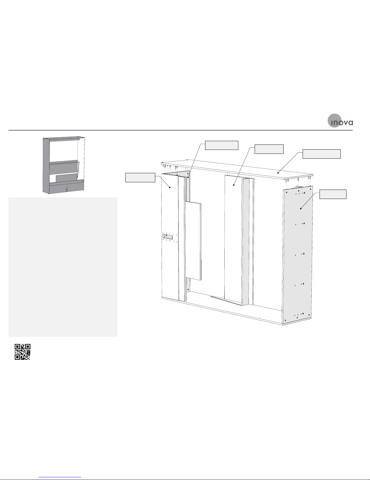
A. Make sure all the Minifix Cams have their
arrows pointing to the nearest edge of the
panels.
B. Li the Le Cabinet Side, flip it over, and
place it on the partly assembled cabinet
as shown. You may need to shi the parts
slightly to get the dowels and pins to line up
with the holes.
C. Tighten all the Minifix Cams as in Step 4.
D. The Bed Cabinet is now complete and ready
to stand up.
STEP 6: Attach Left Cabinet Side to the Cabinet Assembly
Use this version of Step 6 if your TableBed is an Open Back Model
Cabinet Bottom
Cabinet Front
Cabinet Back
Cabinet Side, Left
Cabinet Top
Page 19
Tech support is readily available if needed
Email: [email protected]
Phone: 866.528.2804
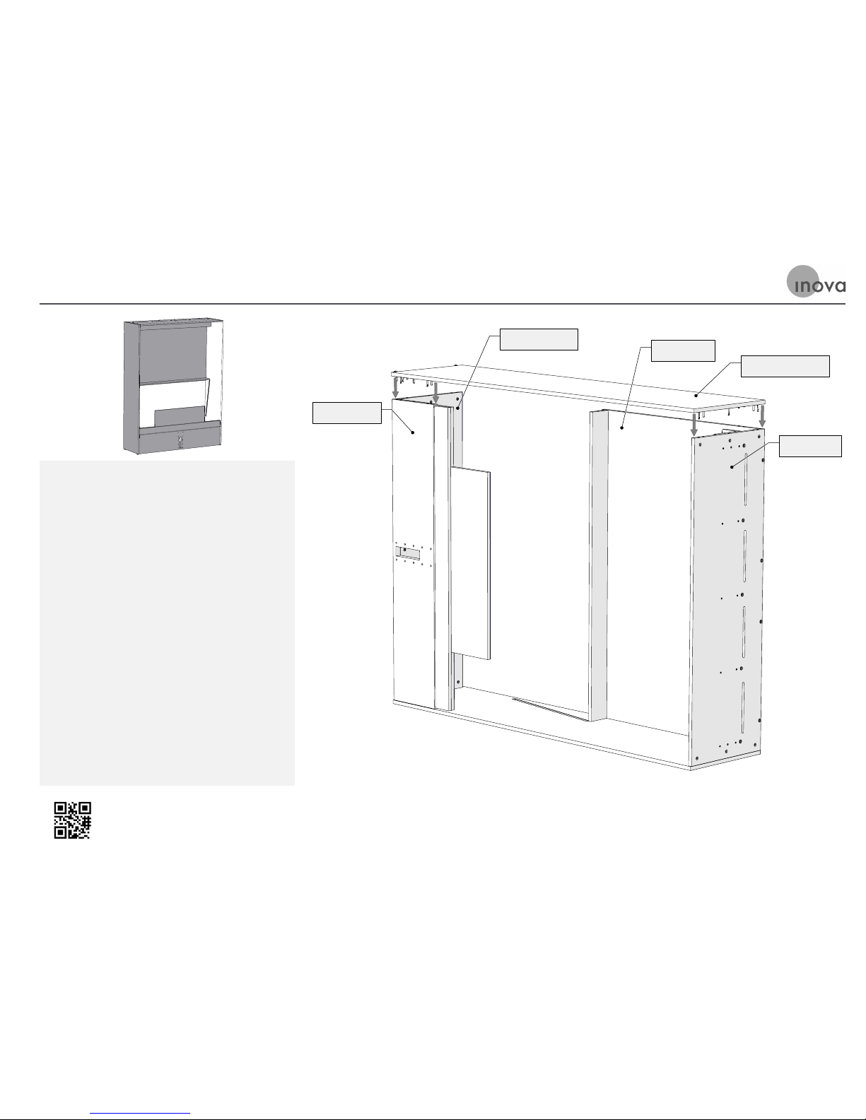
STEP 6: Attach Left Cabinet Side to the Cabinet Assembly
Use this version of Step 6 if your TableBed is a Closed Back Model
A. Make sure all the Minifix Cams have their
arrows pointing to the nearest edge of the
panels.
B. Li the Le Cabinet Side, flip it over, and
place it on the partly assembled cabinet
as shown. You may need to shi the parts
slightly to get the dowels and pins to line up
with the holes.
C. Tighten all the Minifix Cams as in Step 4.
D. The Bed Cabinet is now complete and ready
to stand up.
Cabinet Bottom
Cabinet Front
Closed Back
Cabinet Side, Left
Cabinet Top
Page 20
Tech support is readily available if needed
Email: [email protected]
Phone: 866.528.2804
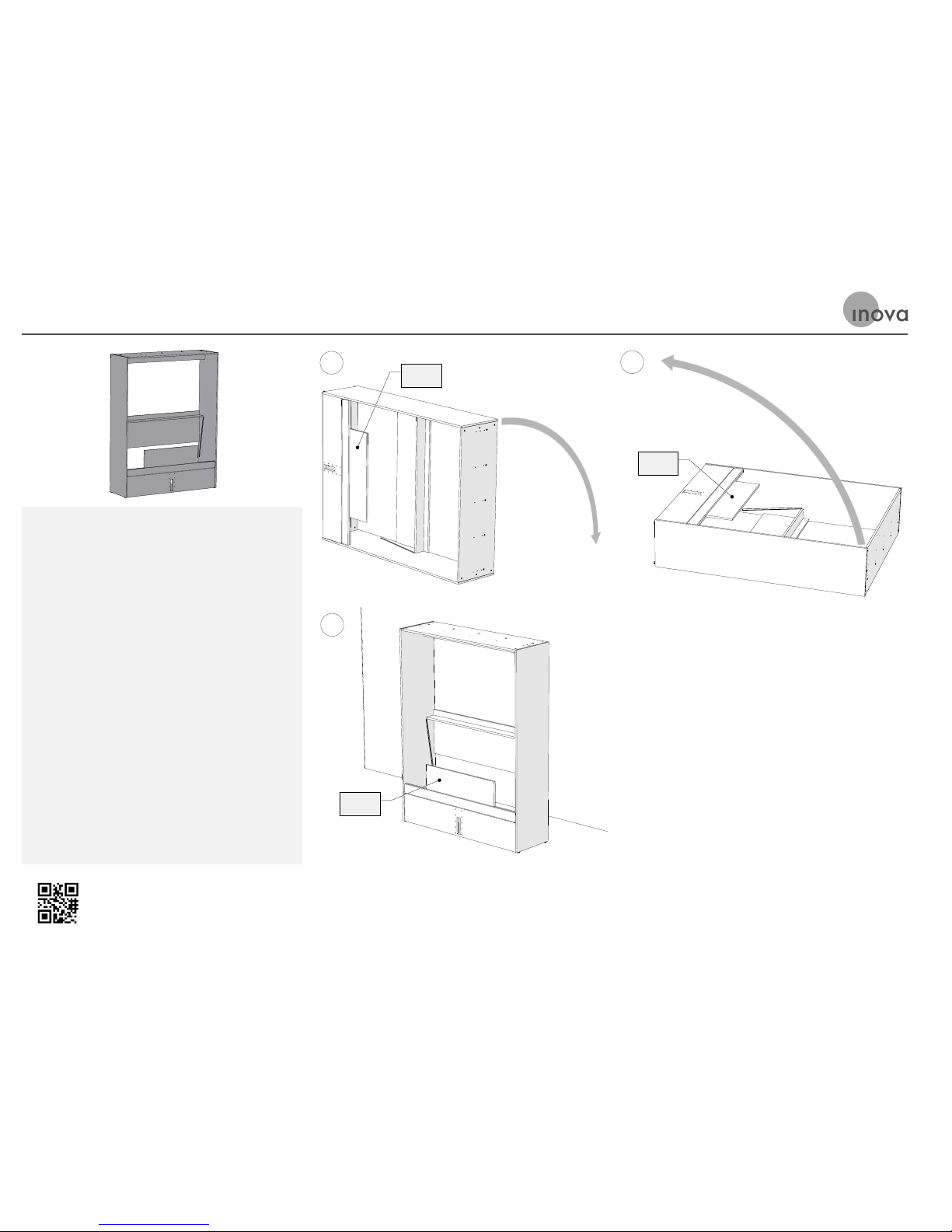
A. It is recommended this step is done by two
people for safety. Carefully lay the Cabinet
over as shown, using padding on the floor
to protect the cabinet from being scratched.
Guide the Flipper as the Cabinet is lowered.
B. Raise the Cabinet as shown. The Flipper
will naturally trail along with the Cabinet.
Make sure the Flpper does not pivot and fall
down when the Cabinet gets to its standing
position.
C. Carefully “walk” the standing Cabinet so that
it is about two feet from the wall where it
will be placed when it is finished. Guide the
Flipper as it remains in its vertical position.
ST E P 7: Lay the Cabinet Over on its Back and then Stand it Up
A
Flipper
B
Flipper
C
Flipper
Page 21

Page 22
Tech support is readily available if needed
Email: [email protected]
Phone: 866.528.2804
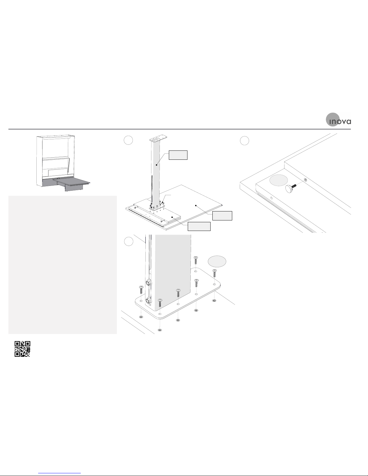
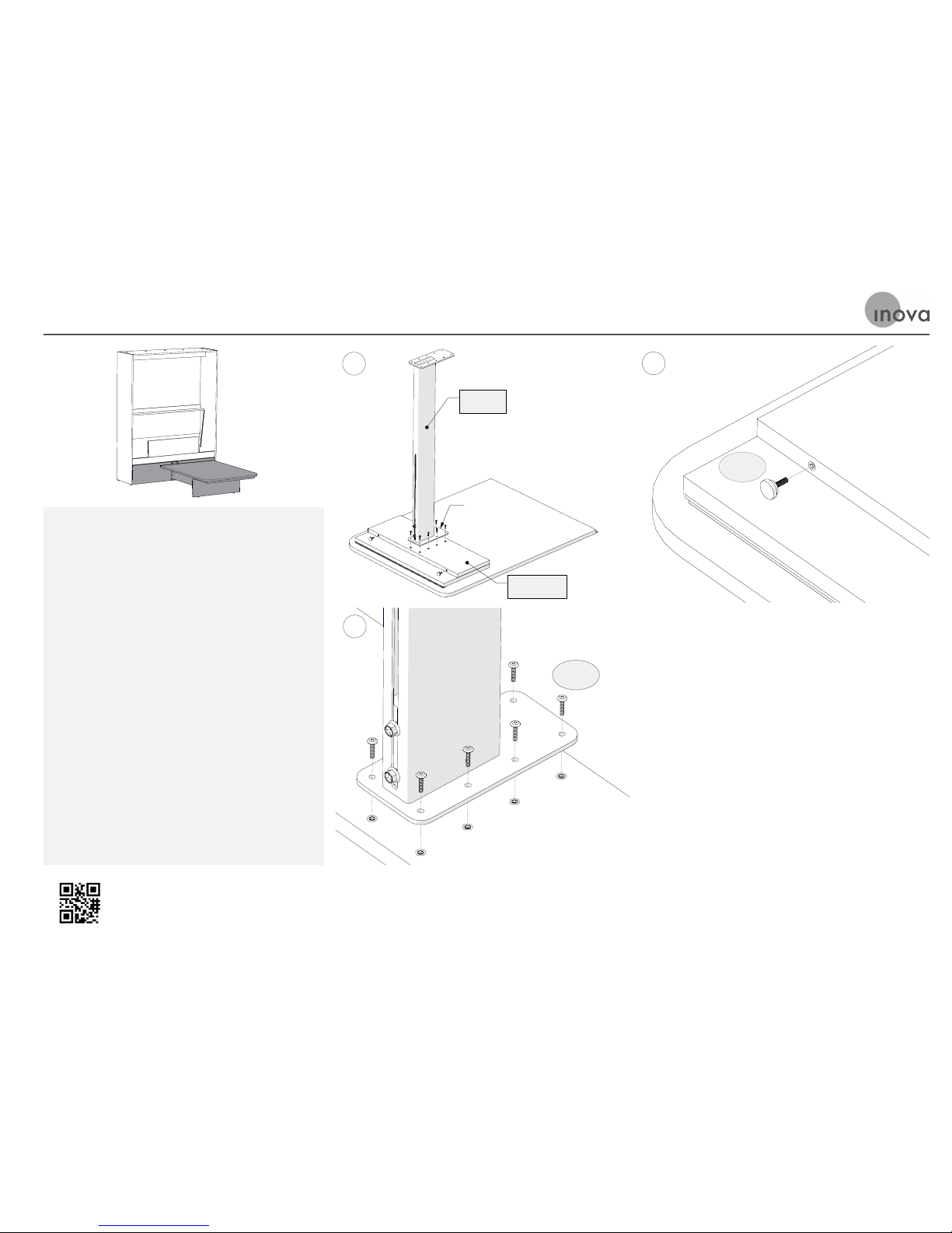
A. Lay the Table Assembly down, as shown,
using padding on the floor to protect the
Tabletop from scratches. Stand the Footrest
on the Lower Leg with the smaller flange
plate downward.
B. If the TableBed will be used on a hard floor,
screw the H-008 Leveler Feet into the boom
edge of the Lower Leg as shown. If it will be
on carpet, do not use the leveler feet.
C. Bolt the Footrest in place with H-020 Panel
Bolts using a 4mm Allen Wrench.
STEP 8: Attach the Footrest to the Table and Leg
A
Tabletop
Small Flange
Lower Leg
Footrest
B
H-008
C
H-020
Use this version of Step 8 if your TableBed has a Table Extension
Page 23
Tech support is readily available if needed
Email: [email protected]
Phone: 866.528.2804
STEP 8: Attach the Footrest to the Table and Leg
Use this version of Step 8 if your TableBed does not have a Table Extension
A. Lay the Table Assembly down, as shown,
using padding on the floor to protect the
Tabletop from scratches. Stand the Footrest
on the Lower Leg with the smaller flange
plate downward.
B. If the TableBed will be used on a hard floor,
screw the H-008 Leveler Feet into the boom
edge of the Lower Leg as shown. If it will be
on carpet, do not use the leveler feet.
C. Bolt the Footrest in place with H-020 Panel
Bolts using a 4mm Allen Wrench.
A
Small Flange
Lower Leg
Footrest
B
H-008
H-020
C
Page 24
Tech support is readily available if needed
Email: [email protected]
Phone: 866.528.2804
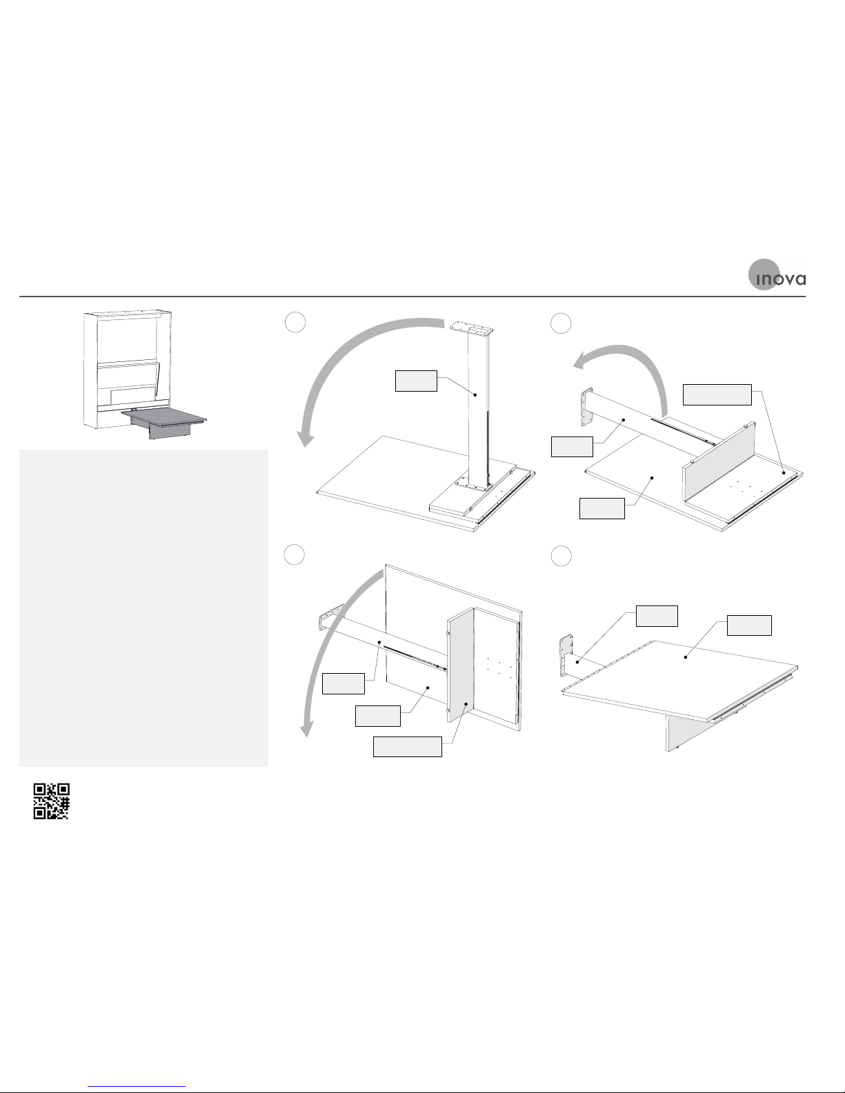
A. Pivot the Footrest down.
B. Carefully turn the Table, Leg, and Footrest
assembly over as shown.
C. Continue to turn the Table, Leg, and Footrest
assembly over as shown.
D. The Tabletop will naturally fall towards the
top of the Footrest.
STEP 9: Turn the Table Assembly Over
A
Footrest
B
Footrest
Leg Assembly
Tabletop
C
Tabletop
Footrest
Leg Assembly
D
Footrest
Tabletop
Use this version of Step 9 if your TableBed has a Table Extension
Page 25
Tech support is readily available if needed
Email: [email protected]
Phone: 866.528.2804
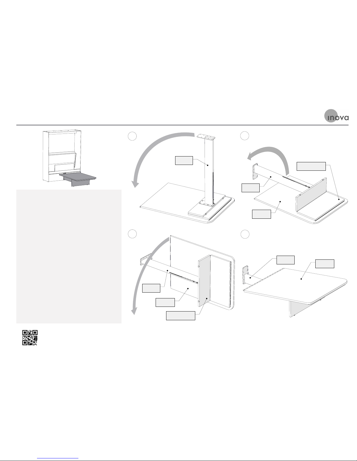
Use this version of Step 9 if your TableBed does not have a Table Extension
STEP 9: Turn the Table Assembly Over
A. Pivot the Footrest down.
B. Carefully turn the Table, Leg, and Footrest
assembly over as shown.
C. Continue to turn the Table, Leg, and Footrest
assembly over as shown.
D. The Tabletop will naturally fall towards the
top of the Footrest.
A
Footrest
B
Footrest
Leg Assembly
Tabletop
C
Tabletop
Footrest
Leg Assembly
D
Footrest
Tabletop
Page 26
Tech support is readily available if needed
Email: [email protected]
Phone: 866.528.2804
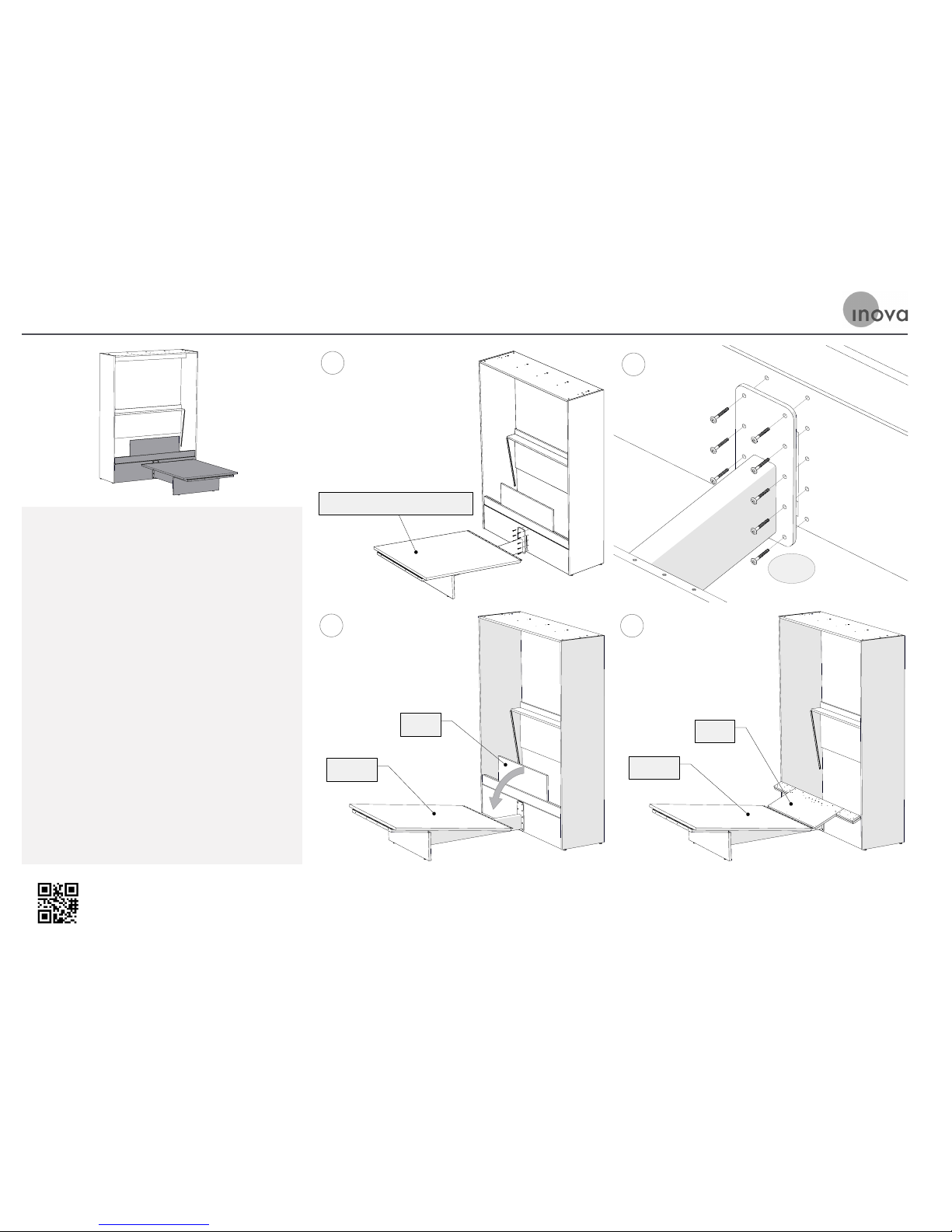
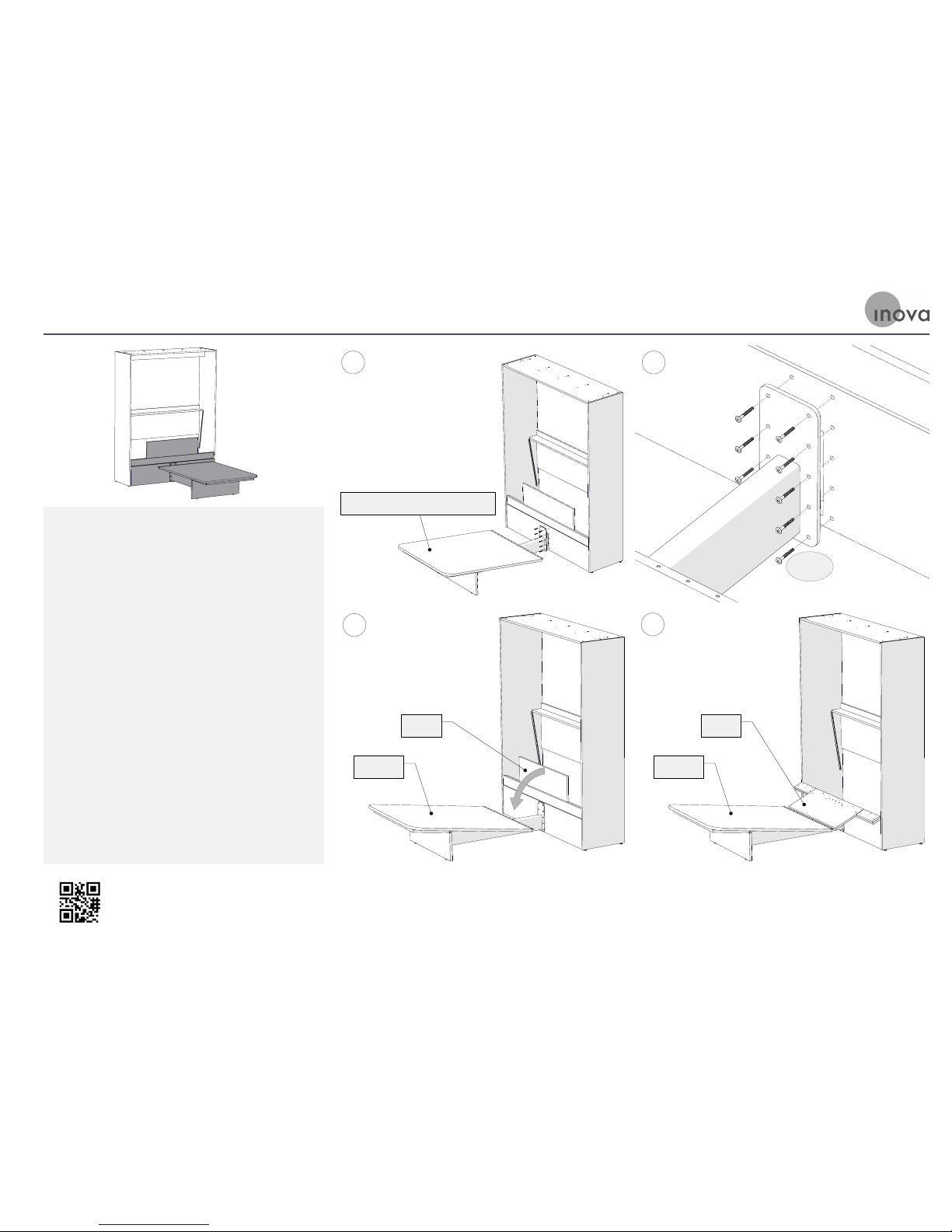
STEP 10: Attach Footrest to Cabinet Front
A. Place the Footrest and Table Assembly
towards the cabinet until it touches the
Cabinet Front.
B. Bolt the Footrest to the Cabinet Front
with H-021 Panel Bolts. Be sure these bolts
are tight; this connection is the key to the
freestanding feature of the TableBed.
C. Pivot the Flipper down as shown.
A
Footrest and Table Assembly
B
H-021
C
Flipper
Tabletop
D
Flipper
Tabletop
Use this version of Step 10 if your TableBed has a Table Extension
Page 27
Tech support is readily available if needed
Email: [email protected]
Phone: 866.528.2804
STEP 10: Attach Footrest to Cabinet Front
Use this version of Step 10 if your TableBed does not have a Table Extension
A. Place the Footrest and Table Assembly
towards the cabinet until it touches the
Cabinet Front.
B. Bolt the Footrest to the Cabinet Front
with H-021 Panel Bolts. Be sure these bolts
are tight; this connection is the key to the
freestanding feature of the TableBed.
C. Pivot the Flipper down as shown.
A
Footrest and Table Assembly
B
H-021
C
Flipper
Tabletop
D
Flipper
Tabletop
Page 28
Tech support is readily available if needed
Email: [email protected]
Phone: 866.528.2804
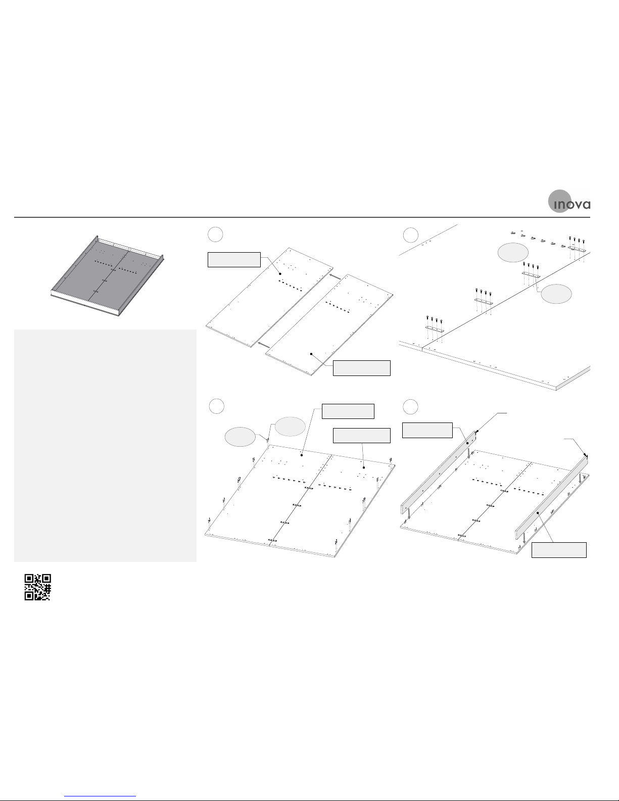
STEP 11: Attach Right and Left Bed Panels & Attach Side Rails to Bed Panels
A. Carefully place the finished side of Bed
Panels on the carpet or other padded surface.
Make sure the area is clear of any hardware
or debris that can cause damage.
B. Aach the Right and Le Bed Panels to each
other using the H-085 Mending Plates and
H-087 Pan Head Screws, making sure that the
top edge of the panels are well aligned when
installing the H-085 Mending Plates.
C. Screw the H-011 minifix pins into the smaller
holes at the outer sides of the Bed Panels. Tap
wood dowels into the larger holes. Be careful
to tap gently; the dowels may dimple the face
of the panels if hit too hard!
D. Place the Side Rails on top of the fiings as
shown. Tighten all of the minifix cams. The
Side Rails must be positioned so that their
ends with pre-installed threaded inserts are
oriented, as shown.
Use this version of Step 11 if your TableBed has a plain front Bed Panel
A
Left Bed Panel
Right Bed Panel
B
H-087
H-085
C
H-003
H-011
Left Bed Panel
Right Bed Panel
D
Threaded Inserts
Side Rail, Left
Threaded Inserts
Side Rail, Right
Page 29
Tech support is readily available if needed
Email: [email protected]
Phone: 866.528.2804
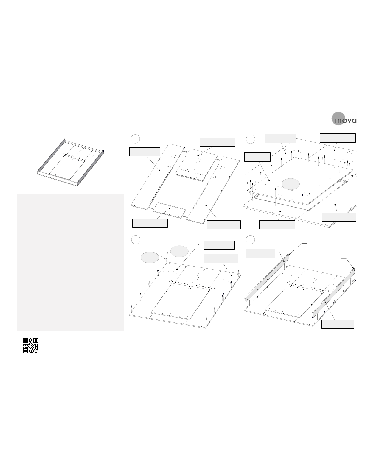
STEP 11: Attach Right and Left Bed Panels & Attach Side Rails to Bed Panels
Use this version of Step 11 if your TableBed has a recessed Bed Panel
A. Carefully place the finished sides of Bed
Panels, as shown, on the carpet or other
padded surface. Make sure the area is clear
of any hardware or debris that can cause
damage.
B. Lay the Mirror Panel face down on the
rectangular opening in between the Bed
Panels, and line up the holes of the Mirror
Panel with the holes in the Bed Panels. Make
sure that the ends of the Bed Panels are well
aligned. Screw the Mirror Panel to the Bed
Panels with H-184 auger screws.
C. Screw the H-011 minifix pins into the smaller
holes at the outer sides of the Bed Panels. Tap
wood dowels into the larger holes. Be careful
to tap gently; the dowels may dimple the face
of the panels if hit too hard!
D. Place the Side Rails on top of the fiings as
shown. Tighten all of the minifix cams. The
Side Rails must be positioned so that their
ends with pre-installed threaded inserts are
oriented, as shown.
A
Lower Bed Panel
Left Bed Panel
Upper Bed Panel
Right Bed Panel
B
Lower Bed Panel
Left Bed Panel
Mirror Panel
Right Bed Panel
H-184
Upper Bed Panel
C
H-003
H-011
Left Bed Panel
Right Bed Panel
D
Threaded Inserts
Side Rail, Left
Threaded Inserts
Side Rail, Right
Page 30
Tech support is readily available if needed
Email: [email protected]
Phone: 866.528.2804
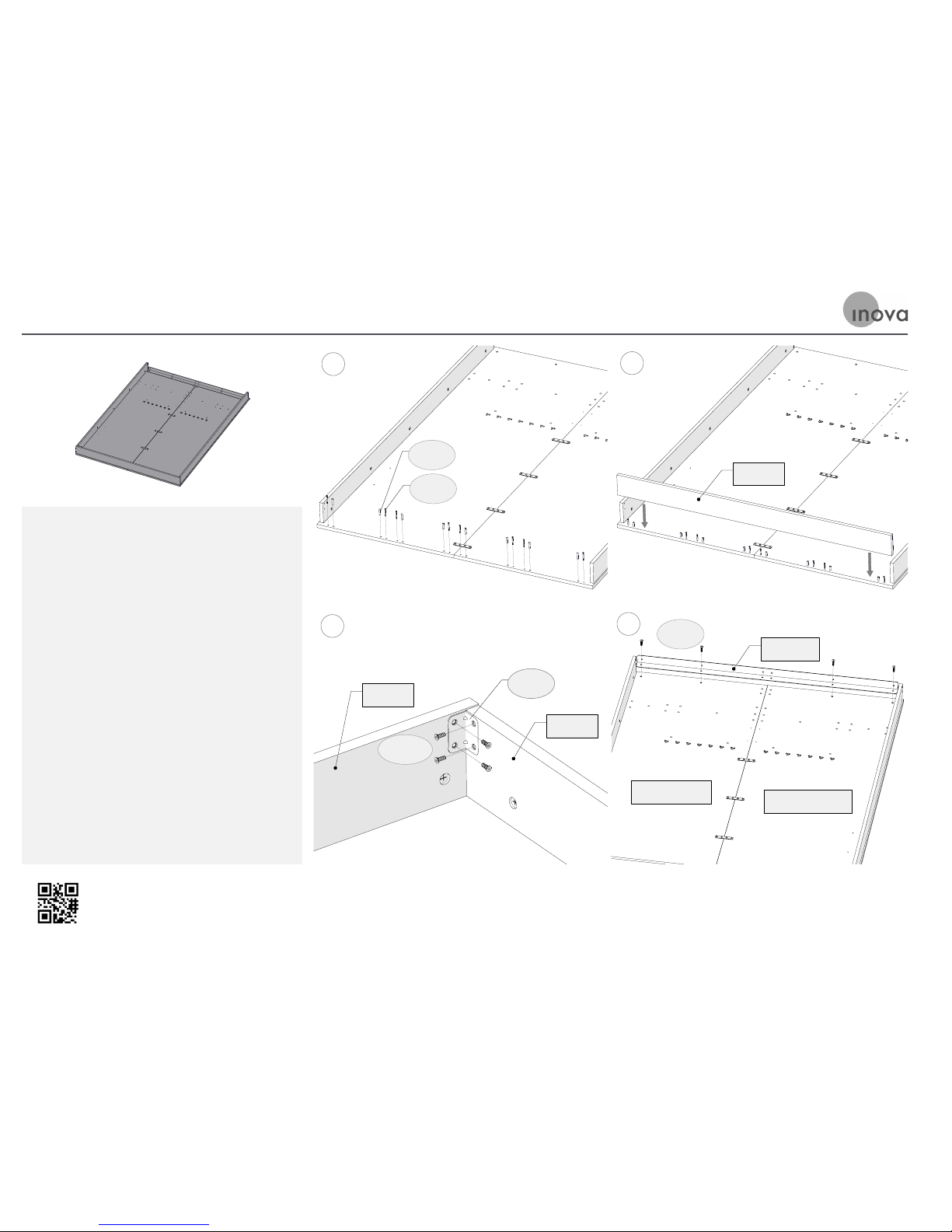
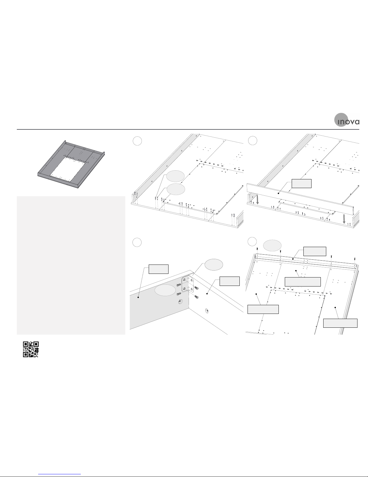
STEP 12: Attach Foot Rail to Bed Panels and Side Rails & Attach Angle Iron
A. Screw the H-011 minifix pins into the smaller
holes at the ends of the Bed Panels, as shown.
Tap wood dowels into the larger holes. Be
careful to tap gently; the dowels may dimple
the face of the panels if hit too hard.
B. Place the Foot Rail on top of the fiings, as
shown. Tighten all of the minifix cams.
C. Aach the Foot Rail to each Side Rail by
connecting the H-077 Wide Angle Brackets
to each corner with H-107s Flat Head Euro
Screws, as shown.
D. Place the Angle Iron on the Bed Platform at
the head of assembly. Align the Angle Iron
holes with the Bed panel Holes. Screw the
H-060 Panhead Machine Screws through the
Angle Iron holes and the Bed Panels to aach
the Angle Iron to the Bed Panels.
Use this version of Step 12 if your TableBed has a plain front Bed Panel
A
H-003
H-011
B
Foot Rail
C
H-077
H-107s
Side Rail
Foot Rail
D
Angle Iron
H-060
Left Bed Panel
Right Bed Panel
Page 31
Tech support is readily available if needed
Email: [email protected]
Phone: 866.528.2804
STEP 12: Attach Foot Rail to Bed Panels and Side Rails & Attach Angle Iron
Use this version of Step 12 if your TableBed has a recessed Bed Panel
A. Screw the H-011 minifix pins into the smaller
holes at the ends of the Bed Panels, as shown.
Tap wood dowels into the larger holes. Be
careful to tap gently; the dowels may dimple
the face of the panels if hit too hard.
B. Place the Foot Rail on top of the fiings, as
shown. Tighten all of the minifix cams.
C. Aach the Foot Rail to each Side Rail by
connecting the H-077 Wide Angle Brackets
to each corner with H-107s Flat Head Euro
Screws, as shown.
D. Place the Angle Iron on the Bed Platform at
the head of assembly. Align the Angle Iron
holes with the Bed panel Holes. Screw the
H-060 Panhead Machine Screws through the
Angle Iron holes and the Bed Panels to aach
the Angle Iron to the Bed Panels.
A
H-003
H-011
B
Foot Rail
C
H-077
H-107s
Side Rail
Foot Rail
D
Angle Iron
H-060
Lower Bed Panel
Left Bed Panel
Right Bed Panel
Page 32
Tech support is readily available if needed
Email: [email protected]
Phone: 866.528.2804
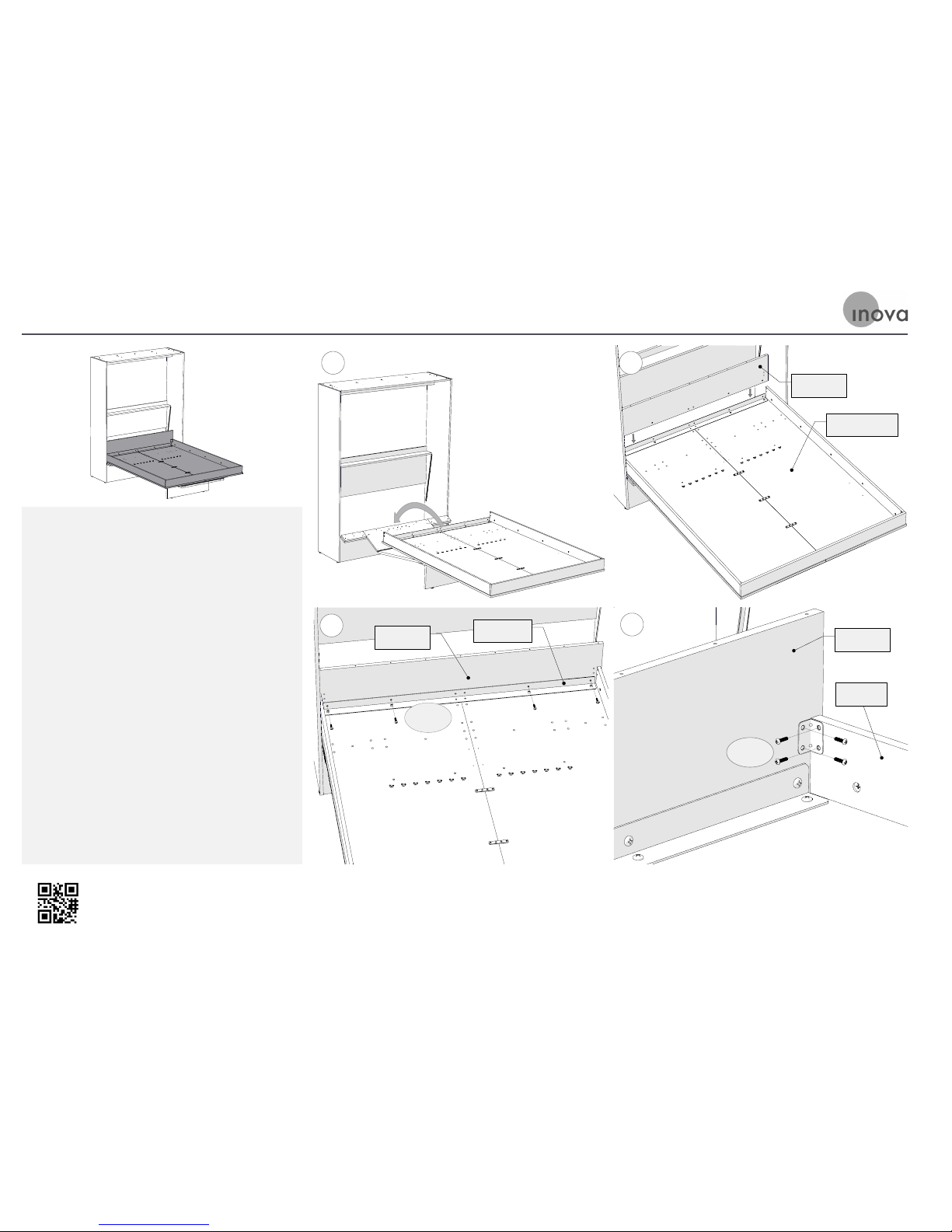
A. With two people, one on each side of the
Bed Platform Assembly, li up the assembly
and locate it into the Bed Cabinet as shown.
Once the Bed Platform has been located, and
is supported by the Tabletop and Flipper
Assembly proceed to the following step for
aachment instructions.
B. Lower the Head Rail into place, behind the
Angle Iron and on top of the Bed Platform.
C. Insert the H-060 Machine Screws through
the Angle Iron and Head Rail, then tighten.
D. Aach the Head Rail to each of the Side Rails
with H-077 Wide Angle Brackets and H-019
Machine Screws at each corner.
STEP 13: Attach Head Rail to Bed Platform & Place Bed Platform into Cabinet
A
Head Rail
Bed Platform
B
Angle Iron
Head Rail
C
H-060
D
Head Rail
H-019
Side Rail
Page 33
Tech support is readily available if needed
Email: [email protected]
Phone: 866.528.2804
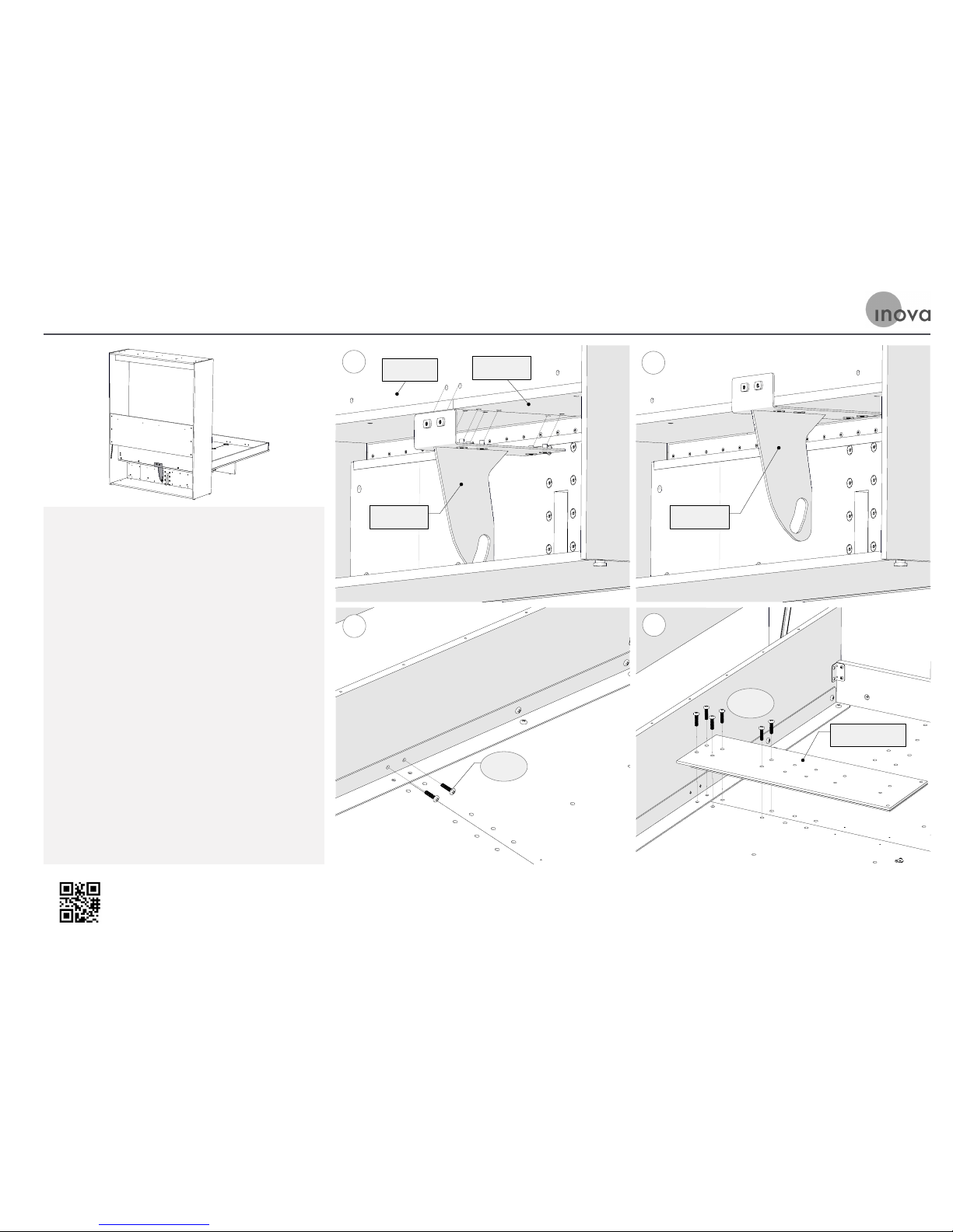
A. From behind the Bed Cabinet, hold the Strut
Plate below the Bed Panels and back face of
the Head Rail, as shown. Align the Strut Plate
threaded inserts with the corresponding
holes in the Bed Panel.
B. Hold the Strut in place from below.
C. From above the Bed Platform, insert the
H-060 Machine Screws through the Angle
Iron, Head Rail, and Strut Plate, then tighten
as shown.
D. Position the Backing Plate as shown. Insert
the H-060 Screws through the Backing Plate,
Bed Panels, and Strut Plate, then tighten.
STEP 14: Attach the Strut Plate to the Bed Platform
Head Rail
A
Strut Plate
Bed Panel
B
Strut Plate
C
H-060
D
Backing Plate
H-060
Page 34
Tech support is readily available if needed
Email: [email protected]
Phone: 866.528.2804
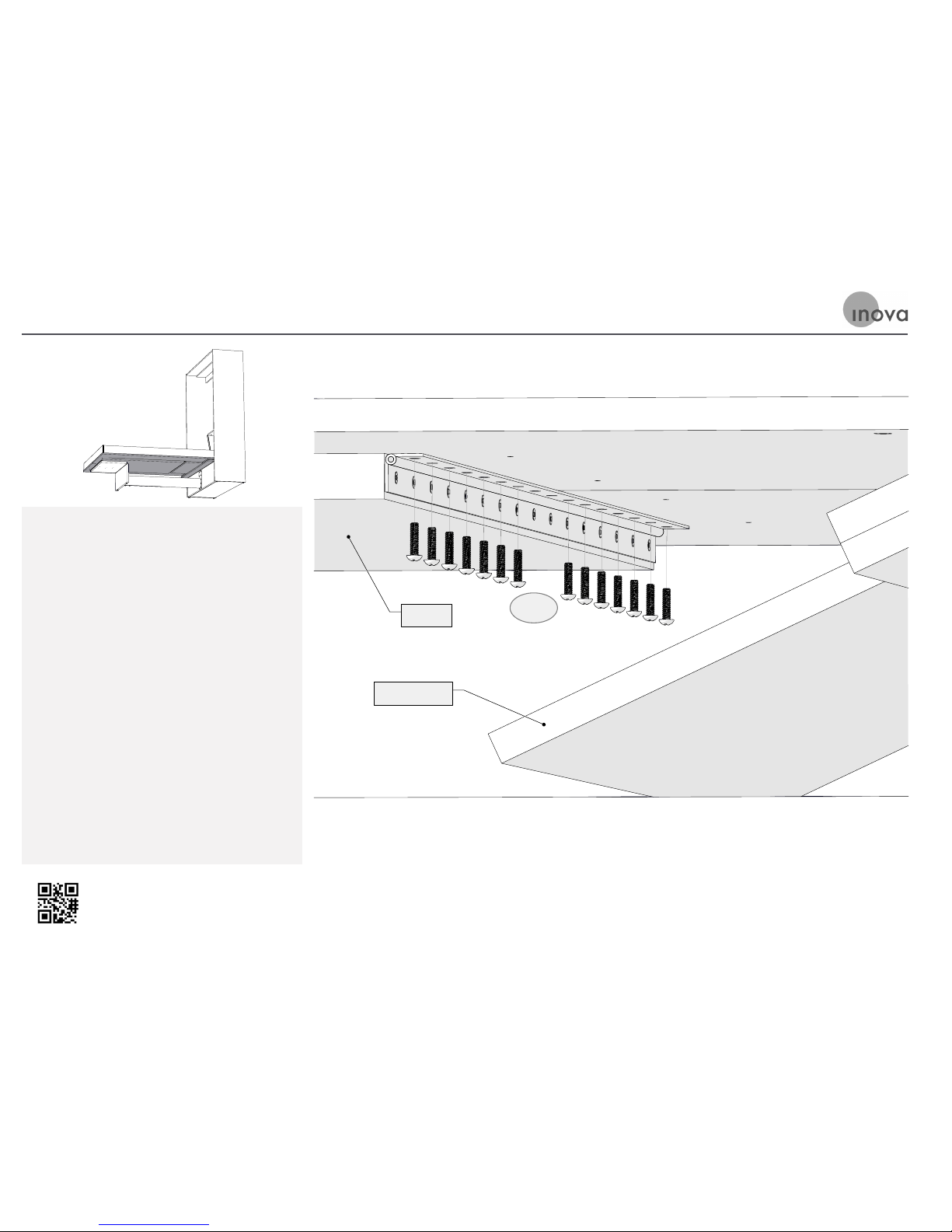
A. Under the Bed Platform, towards the Cabinet,
line up the holes in the hinge at the end of
the Tabletop with the corresponding holes in
the Bed Platform.
B. Bolt the H-019 Machine Screws upwards
through the holes in the hinge, through the
Bed Panels, and into the T-Nuts that are
already set in the Bed Panels on the other
side.
C. TIP: It is best to start a H-019 Machine Screw
at each end of the hinge. Once the hinge is
aligned this way, you can finish inserting all
of the machine screws and tightening them.
STEP 15: Attach the Table Hinge to the Bed Platform
Tabletop
H-019
Flipper Center
Page 35
Tech support is readily available if needed
Email: [email protected]
Phone: 866.528.2804
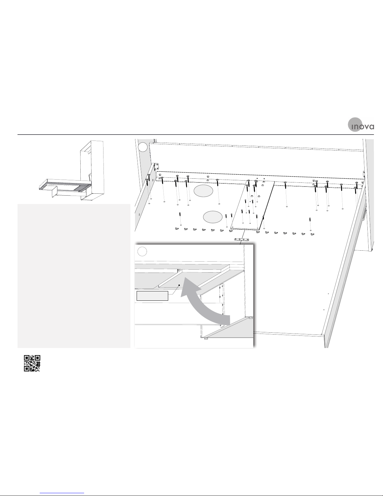
A. From underneath the Bed Platform, prop or
hold the Flipper up against the boom of the
Bed Panels, as shown.
B. There is a series of holes in the Bed Platform
towards the Head Rail. Align these holes with
the holes in the Flipper.
C. Screw the Bed Panels to the Flipper with the
H-065 Panel Screws, as shown.
D. Screw the Bed Panels to the Flipper with the
H-039 Wood Screws, as shown.
STEP 16: Attach the Bed Platform to the Flipper
H-065
H-039
B
Flipper Center
A
Page 36
Tech support is readily available if needed
Email: [email protected]
Phone: 866.528.2804
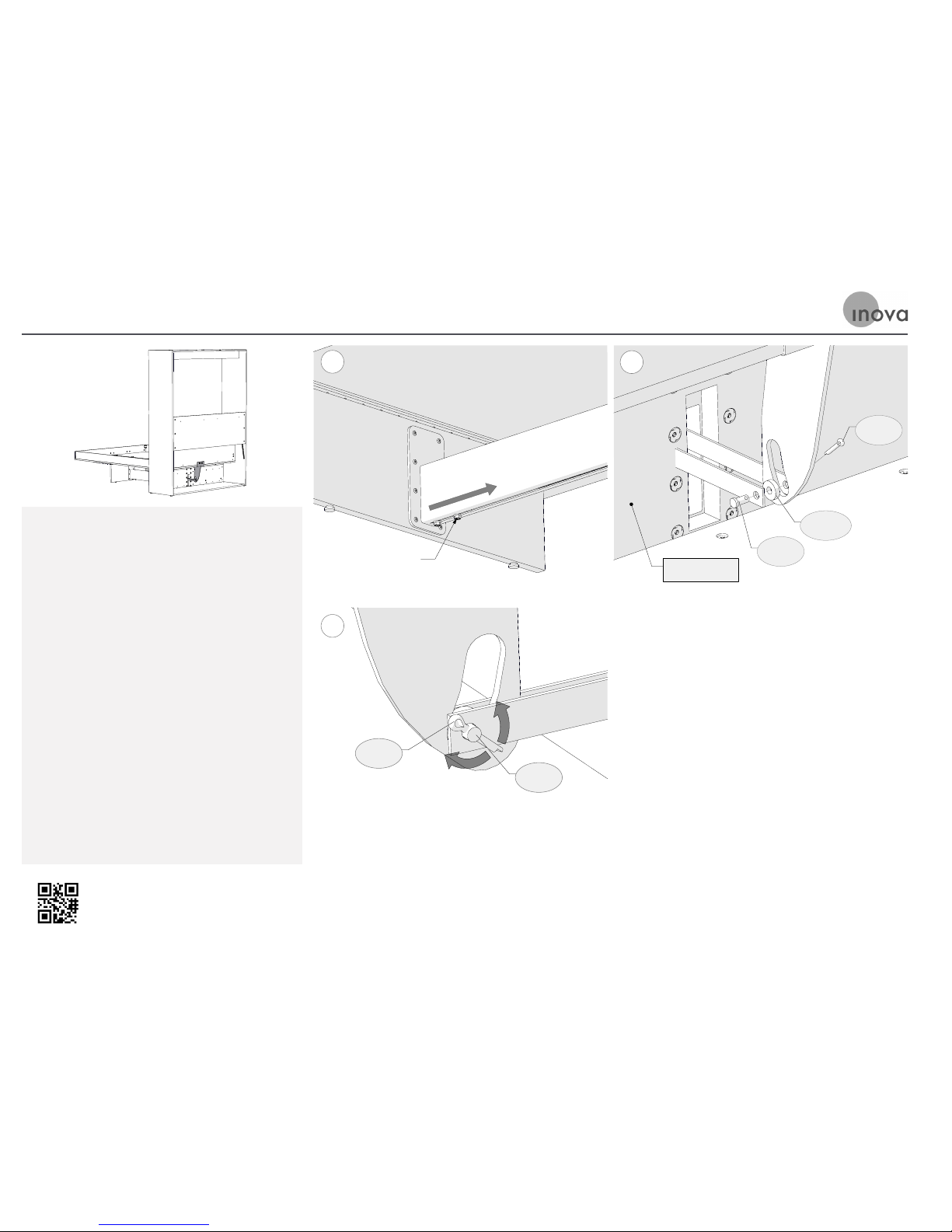
A. Loosen the two Hex Bolts under the Footrest
in the slot near the Table Leg, as shown. Grab
one of the bolts with a pair of pliers and slide
the spring mechanism (inside the footrest)
back towards the Cabinet. The Linking Strips
will come through the rectangular hole in the
Cabinet Front.
B. Place and rest the M-36 Roller Bearing into
the curved slot of the Strut Plate. Relocate
the Linking Strips until their holes line up
with the Roller Bearing. Insert the H-035
Clevis Pin through a Linking Strip, Roller
Bearing, and other Linking Strip.
C. Insert the H-928 Coer Pin through the
Clevis Pin hole. Bend the H-928 Coer Pin
Legs with Pliers to lock the Assembly in
place, as shown.
ST E P 17: Attach the Linking Bars to the Strut Plate
Hex Bolt
A
B
Cabinet Front
M-36C
H-035
H-928
C
H-035
H-928
Page 37
Tech support is readily available if needed
Email: [email protected]
Phone: 866.528.2804
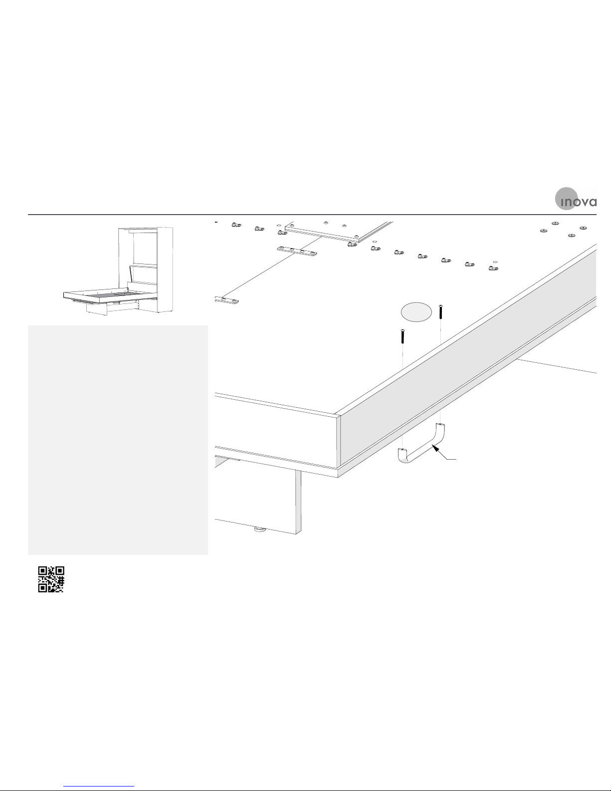
A. Aach the Handles on each side of the Bed
Panels using the H-425 Machine Screws.
STEP 18: Attach the Handles to the Bed Platform
Handle
H-425
Page 38
Tech support is readily available if needed
Email: [email protected]
Phone: 866.528.2804
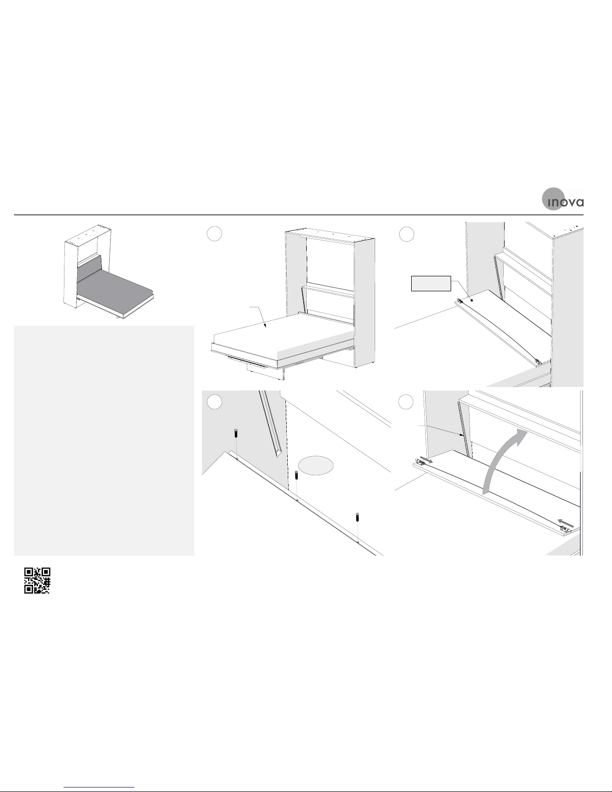
A. At this point the maress can be placed into
the Bed Platform.
B. Locate the Headboard so that the hinge holes
align with the holes of the Head Rail.
C. It is best to start a H-014s Euro Screw at each
end of the hinge. Once the hinge is aligned
this way, you can finish inserting all of the
Euro Screws and tightening them.
D. Pull the Guide Cable away from the
Headboard so that Guide Pins are positioned
in towards the center of the Bed, then pivot
the Headboard toward the back of the Bed
Cabinet. Once the Guide Pins are aligned
with the Guide Tracks, release the Cable so
that the Pins are positioned out into the
Tracks.
STEP 19: Put the Mattress in place & Attach the Headboard to the Head Rail
A
Mattress
B
Headboard
C
H-014s
D
Track
Page 39

Page 40
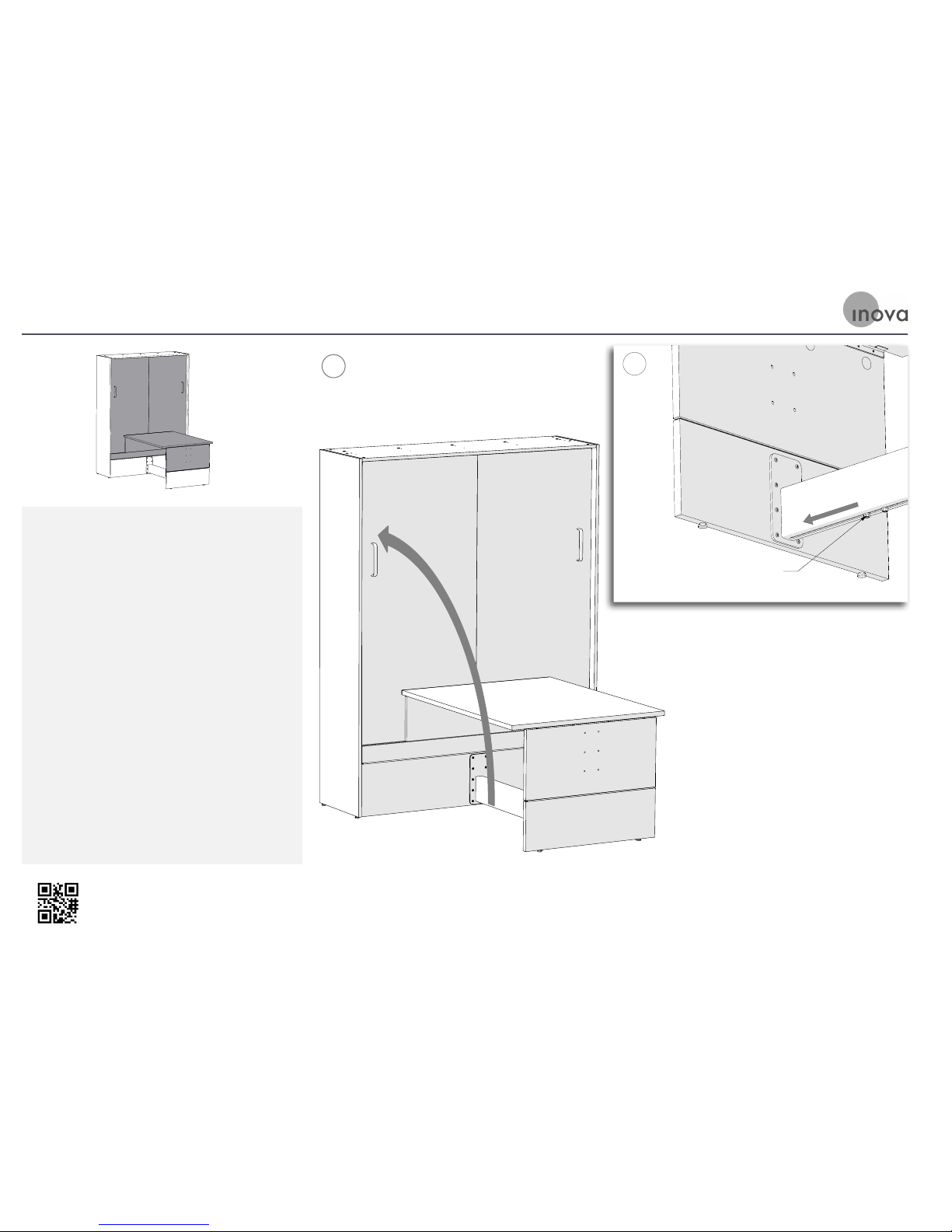
Tech support is readily available if needed
Email: [email protected]
Phone: 866.528.2804
A. Carefully raise the Bed Platform to its
upright position. It will feel heavy because
the spring mechanism is not engaged yet. The
Table will come up as the bed is raised.
B. As the bed is raised, the two bolts shown will
slide forward toward the Table Leg. Grab one
of those bolts with a pair of pliers and slide
the spring mechanism (inside the footrest)
towards the Table Leg. Don’t pull it too tight;
just move it until it stops naturally. Tighten
both bolts firmly with a 9/16” wrench. The
next time the Bed is lowered, the springs will
balance its weight.
A
B
Hex Bolt
Use this version of Step 20 if your TableBed has a Table Extension
STEP 20: Raise the Bed and Tighten the Spring Anchor Bolts
Page 41
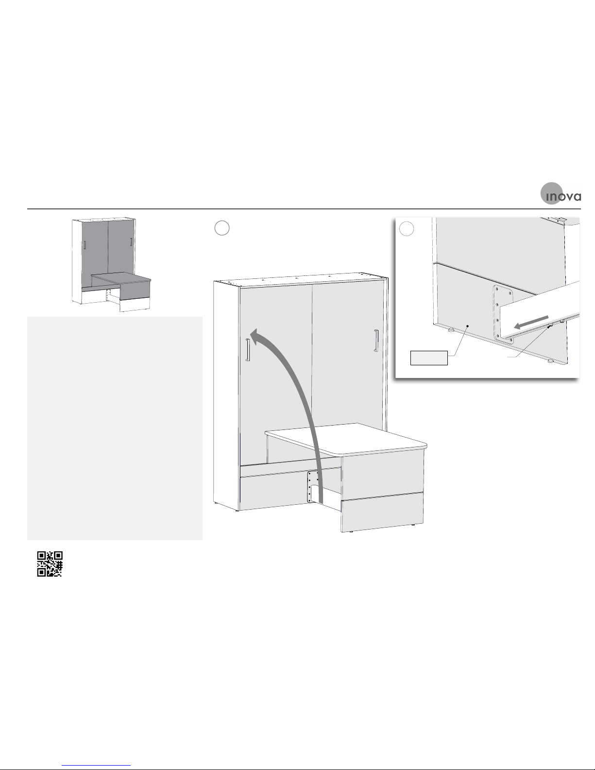
Tech support is readily available if needed
Email: [email protected]
Phone: 866.528.2804
Use this version of Step 20 if your TableBed does not have a Table Extension
STEP 20: Raise the Bed and Tighten the Spring Anchor Bolts
A. Carefully raise the Bed Platform to its
upright position. It will feel heavy because
the spring mechanism is not engaged yet. The
Table will come up as the bed is raised.
B. As the bed is raised, the two bolts shown will
slide forward toward the Table Leg. Grab one
of those bolts with a pair of pliers and slide
the spring mechanism (inside the footrest)
towards the Table Leg. Don’t pull it too tight;
just move it until it stops naturally. Tighten
both bolts firmly with a 9/16” wrench. The
next time the Bed is lowered, the springs will
balance its weight.
A
B
Lower Leg
Hex Bolt
Page 42
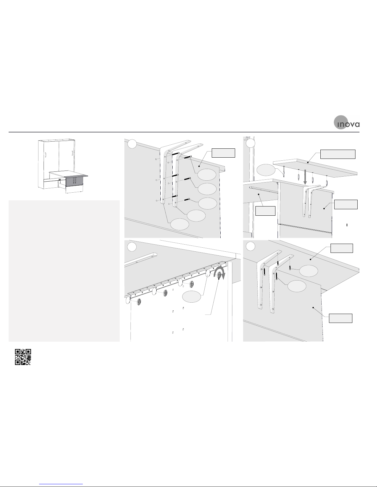
Tech support is readily available if needed
Email: [email protected]
Phone: 866.528.2804
A. Aach the Brackets to the Upper Leg, using
the H-041, H-042, H-043 Machine Screws.
B. Screw the H-007 Maxifix Pins into the metal
fiings on the boom of the Table Extension.
Slide the Pins into the holes in the top of the
Table Leg.
C. Tighten the Maxifix Cams at the inside the
top of the Upper Leg. Cover the Maxifix Cams
by snapping the H-006 plastic caps on them.
D. Aach the Brackets to the underside of the
Table Extension using the H-113 and H-039
Wood Screws in the eaxct holes shown in ‘C’
STEP 21: Attach the Table Extension to the Upper Leg
A
Upper Leg
H-037
H-041
H-042
H-037
H-043
B
Tabletop
Upper Leg
H-007
Table Extension
Maxifix Cam
H-006
C
D
Upper Leg
Extension
H-113
H-039
Use this version of Step 21 if your TableBed has a Table Extension
Page 43

Page 44
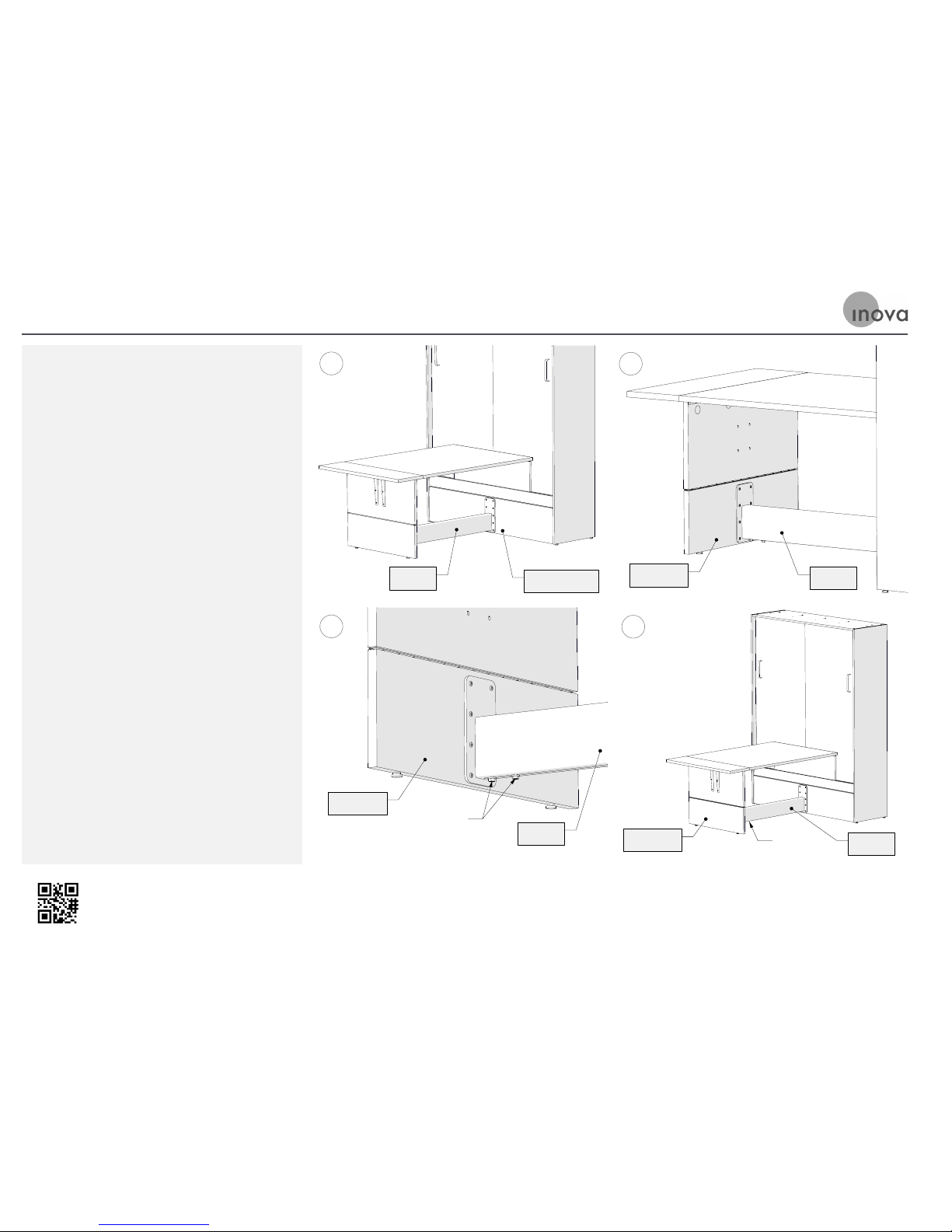
Tech support is readily available if needed
Email: [email protected]
Phone: 866.528.2804
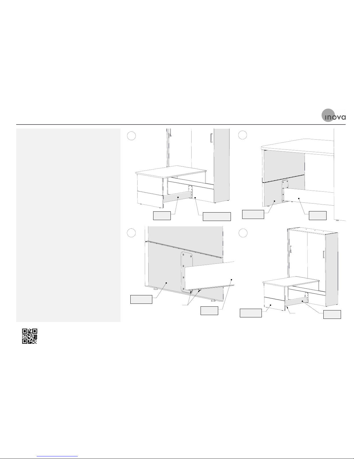
A. The Footrest acts as an outrigger to stabilize
the entire TableBed and allow it to be
freestanding. Aer assembly and periodically
through the life of the unit, check to make
sure the (10) bolts holding the Footrest to the
Cabinet Front remain tight.
B. Periodically check to make sure the (8) bolts
holding it to the Table Leg remain tight.
C. The (2) 3/8” bolts under the Footrest hold
the the spring mechanism anchor bracket in
place. This also holds the adjustment of the
the spring tension for the unit. Maintaining
the tightness of these bolts is crucial to the
safe use of the unit. Check them periodically
to make sure they are completely tightened.
D. Spring Balance of Bed: The position of the
two 3/8” bolts under the Footrest determine
how much spring tension is balancing the
weight of the bed as it is raised and lowered.
The ideal adjustment is to have as much
tension as possible, so the bed is easy to raise
and lower, but not so much that it “floats”
up aer it is lowered. The adjustment MUST
only be made with the bed in the up position
(so there is no tension on the springs while
you are working). To increase the spring
tension, loosen the two 3/8” bolts under the
Footrest, slide them toward the Table Leg,
and retighten them. To decrease the tension,
loosen them, slide them away from the Table
Leg, and retighten them.
STEP 22: Adjust the Spring Tension to the Lower Leg
A
Cabinet Front
Footrest
B
Footrest
Lower Leg
C
Hex Bolts
Lower Leg
Footrest
D
Footrest
Hex Bolts
Lower Leg
Use this version of Step 22 if your TableBed has a Table Extension
Page 45
Tech support is readily available if needed
Email: [email protected]
Phone: 866.528.2804
Use this version of Step 22 if your TableBed does not have a Table Extension
STEP 22: Adjust the Spring Tension to the Lower Leg
A. The Footrest acts as an outrigger to stabilize
the entire TableBed and allow it to be
freestanding. Aer assembly and periodically
through the life of the unit, check to make
sure the (10) bolts holding the Footrest to the
Cabinet Front remain tight.
B. Periodically check to make sure the (8) bolts
holding it to the Table Leg remain tight.
C. The (2) 3/8” bolts under the Footrest hold
the the spring mechanism anchor bracket in
place. This also holds the adjustment of the
the spring tension for the unit. Maintaining
the tightness of these bolts is crucial to the
safe use of the unit. Check them periodically
to make sure they are completely tightened.
D. Spring Balance of Bed: The position of the
two 3/8” bolts under the Footrest determine
how much spring tension is balancing the
weight of the bed as it is raised and lowered.
The ideal adjustment is to have as much
tension as possible, so the bed is easy to raise
and lower, but not so much that it “floats”
up aer it is lowered. The adjustment MUST
only be made with the bed in the up position
(so there is no tension on the springs while
you are working). To increase the spring
tension, loosen the two 3/8” bolts under the
Footrest, slide them toward the Table Leg,
and retighten them. To decrease the tension,
loosen them, slide them away from the Table
Leg, and retighten them.
A
Cabinet Front
Footrest
B
Footrest
Lower Leg
C
Hex Bolts
Lower Leg
Footrest
D
Footrest
Hex Bolts
Lower Leg
Page 46

Page 47

HOW IT WORKS
TableBed | ASSEMBLY MANUAL
Page 48

Tech support is readily available if needed
Email : [email protected]
Phone: 866.528.2 804
TableBed | ASSEMBLY MANUAL
PLEASE NO TE: Your Bed may look different
than what is shown in the pictures a nd
videos throughout this manual
HOW IT WORKS
HOW IT MOVES UP
AND DOWN:
The mechanism that allows the TableBed to
move up and down is spring-loaded and
located inside the FootRest.
As the TableBed is lowered down, gravity is
naturally starting to pull it down. The
springs “kick in” and provide enough
resistance to avoid it from coming down
too qu ick ly.
As the TableBed is raised upward, gravity is
resisting, To make it easier to li, the
springs releases tension, assisting
the bed as it is raised.
TO LOWER THE TABLEBED:
Handles are located on the outside of the
Bed Cabinet (on the Bed Panels) for use to
lower the Bed.
TO RAISE THE TABLEBED:
At the corner of the bed platform, place
hands underneath and li. Start walking
toward the bed cabinet to close. Once at
half-way, grab a handle and guide into
the cabinet.
Page 49

Tech support is readily available if needed
Email : [email protected]
Phone: 866.528.2 804
TableBed | ASSEMBLY MANUAL
PLEASE NO TE: Your Bed may look different
than what is shown in the pictures a nd
videos throughout this manual
HOW IT WORKS (CONT.)
1. Place TableBed in Up Position
(so there is no tension when you are working)
2. Loosen the two 3/8” Bolts under the FootRest
3. To INCREASE tension: slide the bolts toward the
TableLeg (away from TableBed) and tighten.
4. To DECREASE tension: slide the bolts away from
the TableLeg (toward the TableBed) and tighten.
HOW TO
ADJUST TENSION:
STEPS FOR ADJUSTMENT:
To adjust the tension of the TableBed:
Locate the two Bolts underneath the FootRest.
The ideal adjustment is to have as much tension as
possible, so the bed is easy to raise and lower, but not
so much that it “floats” up aer it is lowered.
Page 50

Page 51

TROUBLESHOOTING
TableBed | ASSEMBLY MANUAL
Page 52

Tech support is readily available if needed
Email : [email protected]
Phone: 866.528.2 804
TableBed | ASSEMBLY MANUAL
PLEASE NO TE: Your Bed may look different
than what is shown in the pictures a nd
videos throughout this manual
TROUBLESHOOTING
HOW CAN I ACCESS
BEHIND THE TABLEBED?
If you need to access to the area behind the
bed, you most likey do not have to remove it
from the wall. The Headboard does release,
allowing access behind the Bed.
TO LOWER THE HEADBOARD:
Have someone lower the bed about halfway
and hold it there. On the back of the
Headboard there are guide pins located on
the le and right, with a cable stretched
between them. These pins extend into the
track located on each side of the cabinet,
guiding the Headboard movement as the
bed is raised and lowered. Reach behind
the Headboard and locate the cable. Pull
the cable upward to release the pins on
both side and pivot the Headboard forward
to the maress. Make sure you keep
holding tension on the cable as you pivot
the Headboard to prevent the pins from
scratching the inner faces of the Cabinet
Sides. At this point, the Bed can be lowered
down completely. To re-engage the pins,
pull upward on the tension cable and raise
Headboard, until the pins are aligned
with the track. Release the cable. The pins
should snap out into position, reseing the
headboard for use.
REMOVING BED FROM WALL:
With another person, “walk” each side of the
Cabinet away from wall.
TIP: You may want to place moving pads
underneath cabinet (with another person,
tip cabinet slightly to place pad).
MY TABLEBED IS MAKING
A SQUEAKY NOISE
First, confirm bolts underneath FootRest are
tight and in the desired location
Page 53

Tech support is readily available if needed
Email : [email protected]
Phone: 866.528.2 804
TableBed | ASSEMBLY MANUAL
PLEASE NO TE: Your Bed may look different
than what is shown in the pictures a nd
videos throughout this manual
TROUBLESHOOTING (CONT.)
(See: How It Works - Adjustment). Test.
The TableBed has 5 sets of Hinges that
require periodic lubrication - see
Care & Maintenance
THERE IS A LOUD BANG OR
“GUITAR STRING” NOISE
This noise is most likely coming from the
springs located in the FootRest.
If the TableBed is moving freely, cycle it up
and down 3-5 times to see if this corrects
itself. Test.
If the TableBed does not move freely or this
does not resolve the issue, Contact Us to
further troubleshoot.
CARE & MAINTENANCE
INFORMATION
Please refer to your Welcome Booklet for
detailed information on Care & Maintenance
NEED TO DISASSEMBLE AND
MOVE THE TABLEBED
Reverse assembly steps from manual
TIP: Bag and label hardware per Step.
This will be very helpful when reassembling
the TableBed.
I HAVE A BROKEN PART THAT
NEEDS TO BE REPLACED
Locate your order #
(label located inside Bed Platform)
Take photos of broken part and Bed overall
Upload and Email Us with description of
issue, photos, and include your order # for
easy identification
Page 54

Tech support is readily available if needed
Email : [email protected]
Phone: 866.528.2 804
TableBed | ASSEMBLY MANUAL
PLEASE NO TE: Your Bed may look different
than what is shown in the pictures a nd
videos throughout this manual
THE TABLEBED IS DIFFICULT TO
BRING DOWN (OPEN)
IMPORTANT!: Never Force Bed Open
First, confirm bolts underneath FootRest are
tight and in the desired location (See: How It
Works - Adjustment). Test.
If it still will not open, access behind the
TableBed (see above)
With a flashlight, look closely for any object
(may be small) that may be obstructing the
mechanism from working properly.
Also check that all connections are still in tact
(see assembly manual for proper installation).
Prior to moving Bed back in place, Test.
THE TABLEBED IS DIFFICULT
TO RAISE UP (CLOSE)
IMPORTANT!: Never Force TableBed Closed
First, confirm bolts underneath FootRest are
tight and in the desired location
(See: How It Works - Adjustment). Test.
Remove any pillows. Test.
Confirm maress and bedding has not
exceeded maximum thickness (see original
order for maximum thickness allowed). Test.
If the TableBed still will not raise up, lower
the Headboard (see instructions under
Access Behind Bed) and with a flashlight,
check for an object (may be small) that may
be obstructing the mechanism from working
properly. Remove object. Also confirm all
connections are still in tact with mechanism
(see assembly manual for proper installation).
Set HeadBoard back in place. Test.
If the TableBed still will not raise up,
confirm bolts underneath FootRest are
tight and in the desired location
(See: How It Works - Adjustment). Test.
TROUBLESHOOTING (CONT.)
Page 55

Tech support is readily available if needed
Email : [email protected]
Phone: 866.528.2 804
TableBed | ASSEMBLY MANUAL
PLEASE NO TE: Your Bed may look different
than what is shown in the pictures a nd
videos throughout this manual
FEEDBACK WELCOME
FEEDBACK WELCOME:
This assembly manual was created with you in
mind. Over the years, we have been asked common
questions and received important feedback on our
products and services.
With great care, and through continuous
improvement and learning, we have incorporated
the answers and feedback within these manuals.
We hope you find them useful and easy to use!
With this said, if there is any outstanding question
that you have, please do not hesitate to contact us.
We also welcome any and all feedback about our
product and your experience with it. Email us at
[email protected] or call us at 866.528.2804.
We hope you enjoy your Inova TableBed for many
years to come!
THANK YOU.
 Loading...