

Page 1
BT125, BT200, SL150, SX150, LHF97125,
SX150-BHF, S97125, USO56 AND SL125OC
PNEUMATIC BRAD NAILERS & STAPLERS
ENGRAPADORAS NEUMÁTICAS
CLOUEURS ET AGRAFEURS PNEUMATIQUES
121037REVH 12/05
STANLEY FASTENING SYSTEMS L.P.
OPERATION and MAINTENANCE MANUAL
MANUAL DE OPERACIÓN Y DE MANTENIMIENTO
MANUEL D’INSTRUCTIONS ET D’ENTRETIEN
BEFORE OPERATING THIS TOOL, ALL OPERATORS SHOULD STUDY THIS MANUAL TO
UNDERSTAND AND FOLLOW THE SAFETY WARNINGS AND INSTRUCTIONS. KEEP THESE
INSTRUCTIONS WITH THE TOOL FOR FUTURE REFERENCE. IF YOU HAVE ANY QUESTIONS,
CONTACT YOUR BOSTITCH REPRESENTATIVE OR DISTRIBUTOR.
ANTES DE OPERAR ESTAHERRAMIENTA, TODOS LOS OPERADORES DEBERÁN ESTUDIAR
ESTE MANUAL PARA PODER COMPRENDER Y SEGUIR LAS ADVERTENCIAS SOBRE
SEGURIDAD Y LAS INSTRUCCIONES. MANTENGA ESTAS INSTRUCCIONES CON LA
HERRAMIENTAPARAFUTURA REFERENCIA, SI TIENE ALGUNA DUDA, COMUNÍQUESE CON
SU REPRESENTANTE DE BOSTITCH O CON SU DISTRIBUIDOR.
LIRE ATTENTIVEMENT LE PRÉSENT MANUEL AVANT D’UTILISER L’APPAREIL. PRÉTER UNE
ATTENTION TOUTE PARTICULIÈRE AUX CONSIGNES DE SÉCURITÉ ET AUX
AVERTISSEMENTS. GARDER CE MANUEL AVEC L’OUTIL POUR FUTUR RÉFÉRENCE. SI
VOUS AVEZ DES QUESTIONS, CONTACTEZ VOTRE REPRÉSENTANT OU VOTRE
CONCESSIONNAIRE BOSTITCH.
Page 2

INTRODUCTION
The Bostitch BT125 & BT200, SL150, SX150, SX150-BHF, LHF97125, S97125, USO56 and SL125OC are
precision-built tools, designed for high speed, high volume stapling. These tools will deliver efficient,
dependable service when used correctly and with care. As with any fine power tool, for best performance the
manufacturer’s instructions must be followed. Please study this manual before operating the tool and
understand the safety warnings and cautions. The instructions on installation, operation and maintenance
should be read carefully, and the manuals kept for reference. NOTE: Additional safety measures may be
required because of your particular application of the tool. Contact your Bostitch representative or distributor
with any questions concerning the tool and its use. Bostitch, Inc., East Greenwich, Rhode Island 02818.
INDEX
Safety Instructions . . . . . . . . . . . . . . . . . . . . . . . . . . . . . . . . . . . . . . . . . . . 3
Tool Specifications . . . . . . . . . . . . . . . . . . . . . . . . . . . . . . . . . . . . . . . . . . . 4
Air Supply and Connections. . . . . . . . . . . . . . . . . . . . . . . . . . . . . . . . . . . . . 6
Loading the Tool . . . . . . . . . . . . . . . . . . . . . . . . . . . . . . . . . . . . . . . . . . . . 7
Dial-A-Depth™ . . . . . . . . . . . . . . . . . . . . . . . . . . . . . . . . . . . . . . . . . . . . . . 8
Tool Operation . . . . . . . . . . . . . . . . . . . . . . . . . . . . . . . . . . . . . . . . . . . . . . 9
Maintaining the Pneumatic Tool . . . . . . . . . . . . . . . . . . . . . . . . . . . . . . . . 10
Trouble Shooting . . . . . . . . . . . . . . . . . . . . . . . . . . . . . . . . . . . . . . . . . . . 11
NOTE:
Bostitch tools have been engineered to provide excellent customer satisfaction and are designed to achieve
maximum performance when used with precision Bostitch fasteners engineered to the same exacting
standards. Bostitch cannot assume responsibility for product performance if our tools are used with
fasteners or accessories not meeting the specific requirements established for genuine Bostitch nails,
staples and accessories.
LIMITED WARRANTY — U.S. and Canada Only
Effective December 1, 2005 Bostitch, L.P. warrants to the original retail purchaser that the product purchased is free
from defects in material and workmanship, and agrees to repair or replace, at Bostitch’s option, any defective Bostitch
branded pneumatic stapler or nailer for a period of seven (7) years from date of purchase (one (1) year from the date
of purchase for compressors and tools used in production applications). Warranty is not transferable. Proof of purchase
date required. This warranty covers only damage resulting from defects in material or workmanship; it does not cover
conditions or malfunctions resulting from normal wear, neglect, abuse, accident or repairs attempted or made by other
than our national repair center or authorized warranty service centers. Driver blades, bumpers, o-rings, pistons and
piston rings are considered normally wearing parts. For optimal performance of your Bostitch tool always use genuine
Bostitch fasteners and replacement parts.
THIS WARRANTY IS IN LIEU OF ALL OTHER WARRANTIES, EXPRESS OR IMPLIED, INCLUDING BUT NOT
LIMITED TO THE IMPLIED WARRANTIES OF MERCHANTABILITY OR FITNESS FOR A PARTICULAR
PURPOSE. BOSTITCH SHALL NOT BE LIABLE FOR ANY INCIDENTAL OR CONSEQUENTIAL DAMAGES.
Some states and countries do not allow limitations on how long an implied warranty lasts, or the exclusion or limitation
of incidental or consequential damages, so the above limitations or exclusions may not apply to you. This warranty
gives you specific legal rights, and you may also have other rights which vary from state to state and country to country.
To obtain warranty service in the U.S. return the product, together with proof of purchase, to the U.S. Bostitch National
or Regional Independent Authorized Warranty Service Center. In the U.S. you may call us at 1-800-556-6696 or visit
www.BOSTITCH.com for the location most convenient for you. In Canada please call us at 800-567-7705 or visit
www.BOSTITCH.com
®
™
-2-
Page 3
-3-
SAFETY INSTRUCTIONS
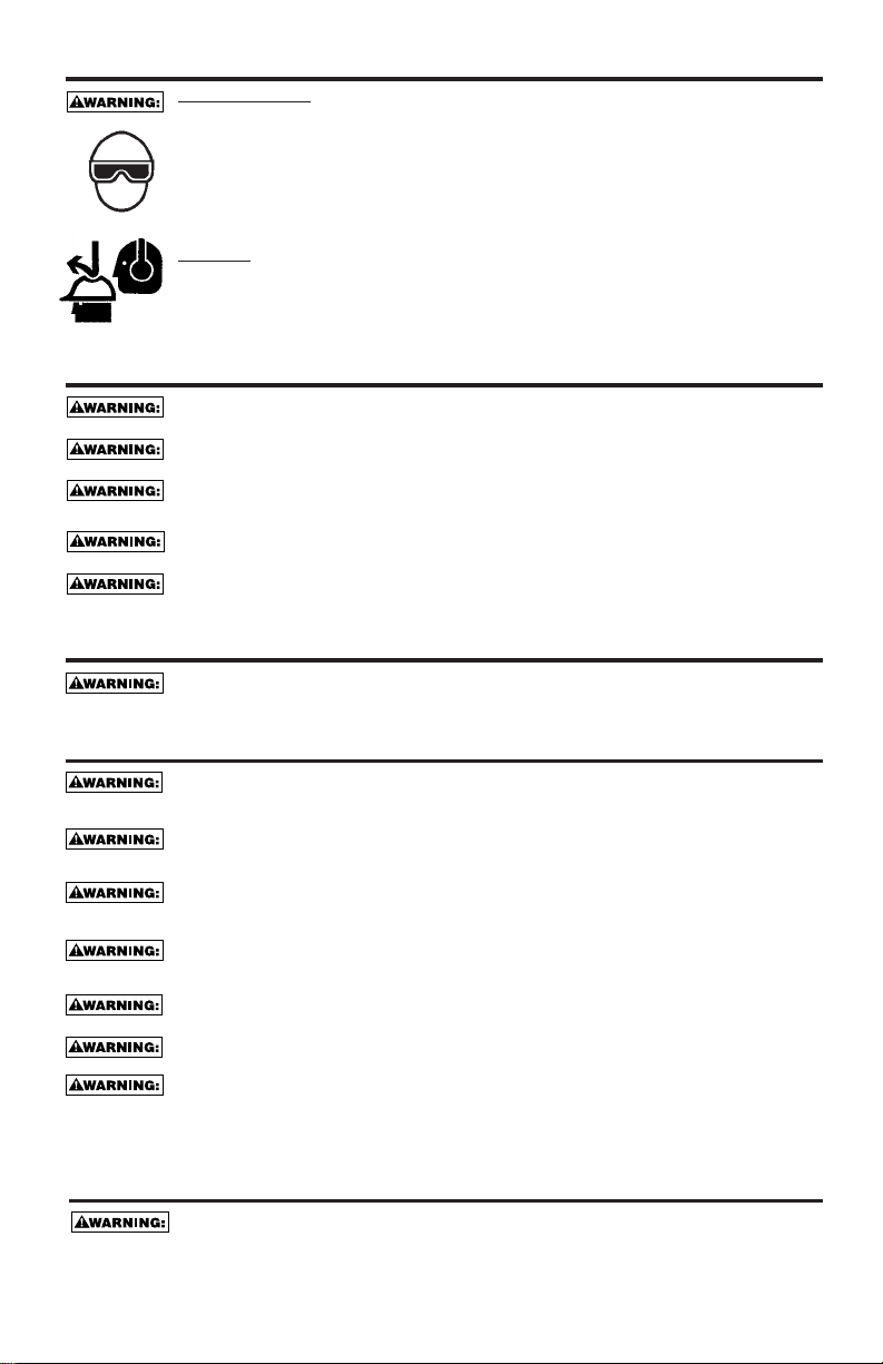
EYE PROTECTION which conforms to ANSI specifications and provides protection against
flying particles both from the FRONT and SIDE should ALWA YS be worn by the operator and
others in the work area when connecting to air supply, loading, operating or servicing this
tool. Eye protection is required to guard against flying fasteners and debris, which could
cause severe eye injury.
The employer and/or user must ensure that proper eye protection is worn. Eye protection
equipment must conform to the requirements of the American National Standards Institute,
ANSI Z87.1 and provide both frontal and side protection. NOTE: Non-side shielded
spectacles and face shields alone do not provide adequate protection.
CAUTION:
Additional Safety Protection will be required in some environments. For
example, the working area may include exposure to noise level which can lead to hearing
damage. The employer and user must ensure that any necessary hearing protection is
provided and used by the operator and others in the work area. Some environments will
require the use of head protection equipment. When required, the employer and user must
ensure that head protection conforming to ANSI Z89.1 is used.
AIR SUPPLY AND CONNECTIONS
Do not use oxygen, combustible gases, or bottled gases as a power source for this tool as
tool may explode, possibly causing injury.
Do not use supply sources which can potentially exceed 200 P.S.I.G. as tool may burst,
possibly causing injury.
The connector on the tool must not hold pressure when air supply is disconnected. If a
wrong fitting is used, the tool can remain charged with air after disconnecting and thus will
be able to drive a fastener even after the air line is disconnected possibly causing injury.
Do not pull trigger or depress contact arm while connected to the air supply as the tool may
cycle, possibly causing injury.
Always disconnect air supply: 1.) Before making adjustments; 2.) When servicing the tool;
3.) When clearing a jam; 4.) When tool is not in use; 5.) When moving to a different work
area, as accidental actuation may occur, possibly causing injury.
LOADING TOOL
When loading tool: 1.) Never place a hand or any part of body in fastener discharge area of
tool; 2.) Never point tool at anyone; 3.) Do not pull the trigger or depress the trip as
accidental actuation may occur, possibly causing injury.
OPERATION
Always handle the tool with care: 1.) Never engage in horseplay; 2.) Never pull the trigger
unless nose is directed toward the work; 3.) Keep others a safe distance from the tool while
tool is in operation as accidental actuation may occur, possibly causing injury.
The operator must not hold the trigger pulled on contact arm tools except during fastening
operation as serious injury could result if the trip accidentally contacted someone or
something, causing the tool to cycle.
Keep hands and body away from the discharge area of the tool. A contact arm tool may
bounce from the recoil of driving a fastener and an unwanted second fastener may be
driven possibly causing injury.
Check operation of the contact arm mechanism frequently. Do not use the tool if the arm
is not working correctly as accidental driving of a fastener may result. Do not interfere with
the proper operation of the contact arm mechanism.
Do not drive fasteners on top of other fasteners or with the tool at an overly steep angle as
this may cause deflection of fasteners which could cause injury.
Do not drive fasteners close to the edge of the work piece as the wood may split, allowing
the fastener to be deflected possibly causing injury.
This nailer produces SPARKS during operation. NEVER use the nailer near flammable
substances, gases or vapors including lacquer, paint, benzine, thinner, gasoline, adhesives,
mastics, glues or any other material that is -- or the vapors, fumes or byproducts of which are -flammable, combustible or explosive. Using the nailer in any such environment could cause an
EXPLOSION resulting in personal injury or death to user and bystanders.
MAINTAINING THE TOOL
When working on air tools note the warnings in this manual and use extra care when
evaluating problem tools.
Page 4

-4-
TOOL AIR FITTING:
This tool uses a free-flow connector plug, 1/4 N.P.T. The inside diameter should be .200” (5mm) or larger. The
fitting must be capable of discharging tool air pressure when disconnected from the air supply.
OPERATING PRESSURE:
70 to 120 p.s.i.g. (4.8 to 8.3 kg/cm2). Select the operating pressure within this range for best fastener
performance. DO NOT EXCEED THE RECOMMENDED OPERATING PRESSURE.
AIR CONSUMPTION:
The LHF97125 and BT125, USO56, SL125OC require 2.8 cubic feet per minute (.08 cubic meters) the BT200,
SX150, SX150-BHF and SL150 require 3.1 cubic feet per minute (.09 cubic meters) of free air to operate at
the rate of 100 nails per minute, at 80 p.s.i. (5.6 kg/cm
2
). Take the actual rate at which the tool will be run to
determine the amount of air required. For instance, if your fastener usage averages 50 nails per minute, you
need 50% of the tool’s c.f.m. which is required to operate the tool at 100 nails per minute.
MODEL LENGTH HEIGHT WIDTH WEIGHT
BT125 10-1/8” (257.1mm) 8-1/4” (209,6 mm) 2-5/16” (59.7 mm) 1.9 lb (1.0 kg)
BT200 10-1/8” (257.1mm) 9-5/8” (244.0 mm) 2-5/16” (59.7 mm) 2.1 lb (1.0 kg)
SX150 10-1/8” (257.1mm) 9-5/8” (244.0 mm) 2-5/16” (59.7 mm) 2.3 lb (1.0 kg)
SL150 10-1/8” (257.1mm) 9-5/8” (244.0 mm) 2-5/16” (59.7 mm) 2.4 lb (1.1 kg)
SX150-BHF 10-1/8” (257.1mm) 9-5/8” (244.0 mm) 2-5/16” (59.7 mm) 3.2 lb (1.4 kg)
LHF97125 10-1/8” (257.1mm) 8-1/4” (209.6 mm) 2-5/16” (59.7 mm) 2.5 lb (1.1 kg)
S97125 10-1/8” (257.1mm) 8-1/4” (209.6 mm) 2-5/16” (59.7 mm) 2.1 lb (1.0 kg)
USO56 10-1/8” (257.1mm) 7-5/8” (178.0 mm) 2-5/16” (59.7 mm) 2.2 lb (1.0 kg)
SL125OC 10-1/8” (257.1mm) 8-1/2” (204.7 mm) 2-5/16” (59.7 mm) 2.3 lb (1.0 kg)
FASTENER SPECIFICATIONS:
TOOL SPECIFICATIONS
All screws and nuts are metric.
TOOL BRAD/STAPLE CROWN WIRE SIZE FASTENER RANGE
MODEL SERIES WIDTH
BT125 BT1300 .050”X.040” (1.27mmX1.04mm) 5/8”-1-1/4”(15mm-32mm)
BT200 BT1300 .050”X.040” (1.27mmX1.04mm) 5/8”-2” (15mm-38mm)
SL150 SL5035 5/16”(8.0mm) .050”X0.035” (1.3X0.89mm) 1/2”-1-1/2”(12mm-38mm)
SX150 SX5035 7/32”(5.6mm) .050”X0.035” (1.3X0.89mm) 1/2”-1-1/2”(12mm-38mm)
SX150-BHF SX5035 7/32”(5.6mm) .050”X0.035” (1.3X0.89mm) 1/2”-1-1/2”(12mm-38mm)
LHF97125 SB97 3/16”(4.7mm) .028”X0.035” (0.7X0.89mm) 1/2”-1-3/8”(12mm-35mm)
S97125 SB97 3/16”(4.7mm) .028”X0.035” (0.7X0.89mm) 1/2”-1-3/8”(12mm-35mm)
USO56 STCR5019 7/16”(11.1mm) .050”X0.019” (1.3X0.48mm) 1/4”-9/16”(6mm-14mm)
SL125OC SL5035 5/16” (8.0mm) .050”x.035” (1.3X0.89mm) 1/2”-1-1/2” (12mm-38mm)
Page 5

-5-
OPERATION
There are three available systems on BOSTITCH pneumatic tools. They are:
1. CONTACT TRIP OPERATION 2. SEQUENTIAL TRIP OPERATION 3. TRIGGER OPERATION
CONTACT TRIP:
The common operating procedure on “Contact Trip” tools is for the operator to contact the work to actuate the
trip mechanism while keeping the trigger pulled, thus driving a fastener each time the work is contacted. This
will allow rapid fastener placement on many jobs. All pneumatic tools are subject to recoil when driving
fasteners. The tool may bounce, releasing the trip, and if unintentionally allowed to recontact the work surface
with the trigger still actuated (finger still holding trigger pulled) an unwanted second fastener will be driven.
SEQUENTIAL TRIP:
The Sequential Trip requires the operator to hold the tool against the work before pulling the trigger. This
makes accurate fastener placement easier. The Sequential Trip allows exact fastener location without the
possibility of driving a second fastener on recoil, as described under “Contact Trip”. The Sequential Trip Tool
has a positive safety advantage because it will not accidentally drive a fastener if the tool is contacted against
the work – or anything else – while the operator is holding the trigger pulled.
TRIGGER OPERATED:
The Trigger Operated model is cycled by actuation of the trigger only. This model does not have a Contact
Arm and is intended for use only where a Contact Arm CANNOT be used to satify the requirements of the
application. The Trigger Operated tool will cycle each time the trigger is actuated.
MODEL IDENTIFICATION:
Refer to Operation Instructions on page 9 before proceeding to use this tool.
CONTACT TRIP SEQUENTIAL TRIP TRIGGER OPERATED
Identified by: Identified by: Identified by:
BLACK TRIGGER GRAYTRIGGER BLACK TRIGGER
Page 6

AIR SUPPLY AND CONNECTIONS
Do not use oxygen, combustible gases, or bottled gases as a power source for this tool as
tool may explode, possibly causing injury.
FITTINGS:
Install a male plug on the tool which is free flowing and which will release air pressure from the tool when
disconnected from the supply source.
HOSES:
Air hoses should have a minimum of 150 p.s.i. (10.6 kg/cm2) working pressure rating or 150 percent of the
maximum pressure that could be produced in the air system. The supply hose should contain a fitting that will
provide “quick disconnecting” from the male plug on the tool.
SUPPLY SOURCE:
Use only clean regulated compressed air as a power source for this tool. NEVER USE OXYGEN, COMBUSTIBLE
GASES, OR BOTTLED GASES, AS A POWER SOURCE FOR THIS TOOLAS TOOL MAY EXPLODE.
REGULATOR:
A pressure regulator with an operating pressure of 0 - 125 p.s.i. (0 - 8.79 KG/CM2) is required to control the
operatiing pressure for safe operation of this tool. Do not connect this tool to air pressure which can potentially
exceed 200 p.s.i. (14 KG/CM
2
) as tool may fracture or burst, possibly causing injury.
OPERATING PRESSURE:
Do not exceed recommended maximum operating pressure as tool wear will be greatly increased. The air
supply must be capable of maintaining the operating pressure at the tool. Pressure drops in the air supply can
reduce the tool’s driving power. Refer to “TOOLSPECIFICATIONS” for setting the correct operating pressure
for the tool.
FILTER:
Dirt and water in the air supply are major causes of wear in pneumatic tools. A filter will help to get the best
performance and minimum wear from the tool. The filter must have adequate flow capacity for the specific
installation. The filter has to be kept clean to be effective in providing clean compressed air to the tool. Consult
the manufacturer’s instructions on proper maintenance of your filter. A dirty and clogged filter will cause a
pressure drop which will reduce the tool’s performance.
-6-
Page 7
LOADING THE BT125, BT200, SL150, SX150, LHF97125,
USO56, SL125OC & S97125
-7-
EYE PROTECTION which conforms to ANSI specifications and provides protection against
flying particles both from the FRONT and SIDE should ALWA YS be worn by the operator and
others in the work area when connecting to air supply, loading, operating or servicing this
tool. Eye protection is required to guard against flying fasteners and debris, which could
cause severe eye injury.
The employer and/or user must ensure that proper eye protection is worn. Eye protection
equipment must conform to the requirements of the American National Standards Institute,
ANSI Z87.1 and provide both frontal and side protection. NOTE: Non-side shielded
spectacles and face shields alone do not provide adequate protection.
TO PREVENT ACCIDENTAL INJURIES:
•Never place a hand or any other part of the body in nail discharge area of tool while
the air supply is connected.
• Never point the tool at anyone else.
• Never engage in horseplay.
• Never pull the trigger unless nose is directed at the work.
•Always handle the tool with care.
• Do not pull the trigger or depress the trip mechanism while loading the tool.
ON
.
.
S
3
.
.
CO
.
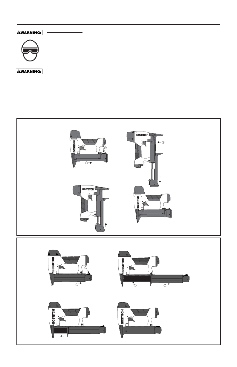
LOADING THE SL150, SX150, LHF97125, USO56, SL125OC, S97125
LOADING THE BT125, BT200
1. OPEN MAGAZINE FULLY
2. TURN TOOL SIDEWAY
WITH DISCHARGE AREA
POINTED AWAY FROM
YOURSELF AND OTHERS.
. LOAD STAPLES IN CHANNEL
1. DEPRESS MAGAZINE RELEASE BUTT
2. PULL BACK MAGAZINE
PUSH MAGAZINE FORWARD
NTINUE PUSHING UNTIL LATCH IS ENGAGED
1
1. DEPRESS MAGAZINE RELEASE BUTTON.
2. PULL BACK MAGAZINE.
PUSH MAGAZINE FORWARD.
2
2
1. OPEN MAGAZINE FULLY.
2. INSERT FASTENERS, POINTS MUST BE
CONTINUE PUSHING UNTIL LATCH IS ENGAGED.
1
AGAINST BOTTOM OF MAGAZINE.
Page 8
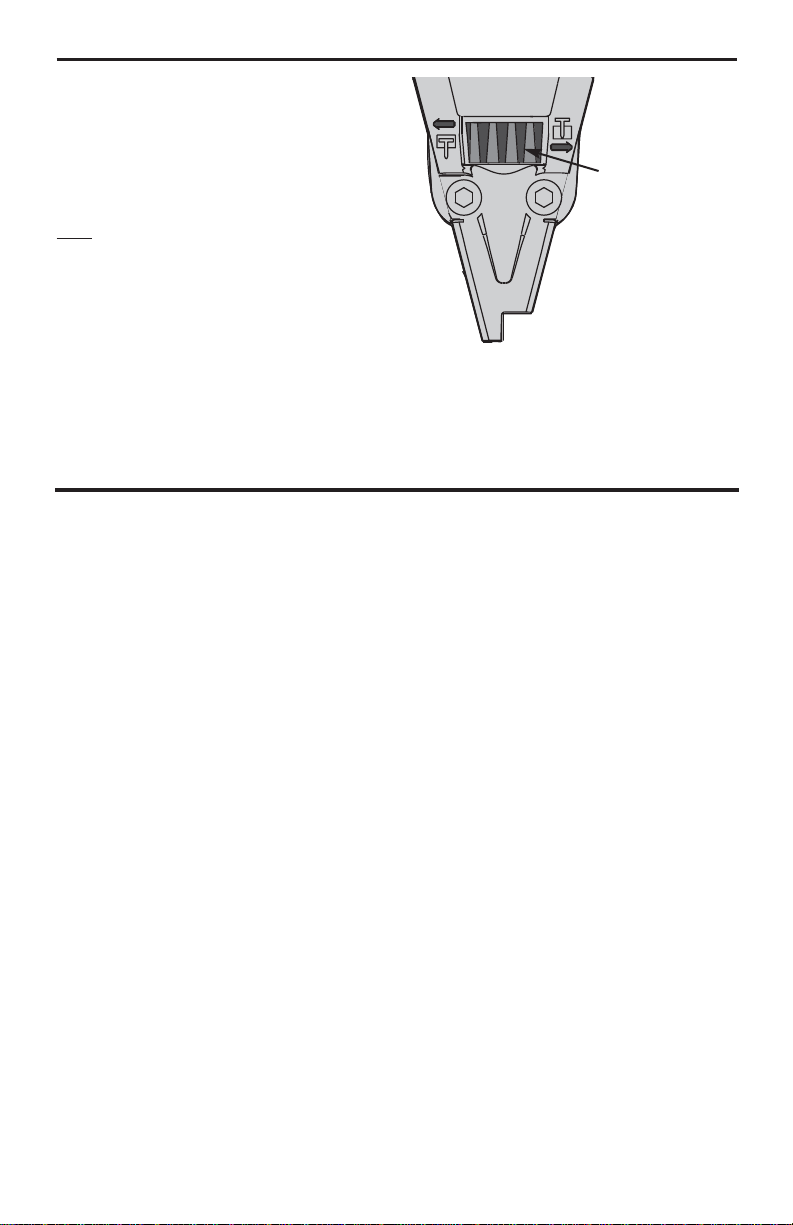
DIAL-A-DEPTH™ FASTENER CONTROL ADJUSTMENT
The DIAL-A-DEPTH™ Fastener control adjustment
feature provides close control of the fastener drive
depth: from flush with the work surface to shallow or
deep countersink.
First set the air pressure for consistent drive in the
specific work as described on page 4, then use the
DIAL-A-DEPTH™ fastener control adjustment to give
the desired depth of drive.
Note:
Any tools that do not come in a kit
will have a non-adjustable depth of drive.
IN ADDITION TO THE OTHER WARNINGS CONTAINED IN THIS
MANUAL OBSERVE THE FOLLOWING FOR SAFE OPERATION
• Use the BOSTITCH pneumatic tool only for the purpose for which it was designed.
• Never use this tool in a manner that could cause a fastener to be directed toward the user
or others in the work area.
• Do not use the tool as a hammer.
• Always carry the tool by the handle. Never carry the tool by the air hose.
• Do not alter or modify this tool from the original design or function without approval from
BOSTITCH, INC.
• Always be aware that misuse and improper handling of this tool can cause injury to
yourself and others.
• Never clamp or tape the trigger or contact trip in an actuated position.
• Never leave a tool unattended with the air hose attached.
• Do not operate this tool if it does not contain a legible WARNING LABEL.
•Do not continue to use a tool that leaks air or does not function properly. Notify your nearest
Bostitch representative if your tool continues to experience functional problems.
-8-
DEPTH ADJUSTMENT NUT
Page 9

-9-
TOOL OPERATION
EYE PROTECTION which conforms to ANSI specifications and provides protection against
flying particles both from the FRONT and SIDE should ALWAYS be worn by the operator
and others in the work area when connecting to air supply, loading, operating or servicing
this tool. Eye protection is required to guard against flying fasteners and debris, which
could cause severe eye injury.
The employer and/or user must ensure that proper eye protection is worn. Eye protection
equipment must conform to the requirements of the American National Standards Institute,
ANSI Z87.1 and provide both frontal and side protection. NOTE: Non-side shielded
spectacles and face shields alone do not provide adequate protection.
BEFORE HANDLING OR OPERATING THIS TOOL:
I. READ AND UNDERSTAND THE WARNINGS CONTAINED IN THIS MANUAL.
II. REFER TO “TOOL SPECIFICATIONS” IN THIS MANUAL TO IDENTIFY THE
OPERATING SYSTEM ON YOUR TOOL.
There are three available systems on BOSTITCH pneumatic tools. They are:
1. CONTACT TRIP OPERATION 2. SEQUENTIAL TRIP OPERATION 3. TRIGGER OPERATION
OPERATION
1. CONTACT TRIP OPERATION:
The CONTACTTRIP MODEL tool contains a contact trip that operates in conjunction with the trigger to
drive a fastener. There are two methods of operation to drive fasteners with a contact trip tool.
A. SINGLE FASTENER PLACEMENT: To operate the tool in this manner, first position the contact trip
on the work surface, WITHOUT PULLING THE TRIGGER. Depress the contact trip until the nose
touches the work surface and then pull the trigger to drive a fastener. Do not press the tool against
the work with extra force. Instead, allow the tool to recoil off the work surface to avoid a second
unwanted fastener. Remove your finger from the trigger after each operation.
B. RAPID FASTENER OPERATION: To operate the tool in this manner, hold the tool with the contact
trip pointing towards but not touching the work surface. Pull the trigger and then tap the contact trip
against the work surface using a bouncing motion. Each depression of the contact trip will cause a
fastener to be driven.
The operator must not hold the trigger pulled on contact trip tools except during fastening
operation, as serious injury could result if the trip accidentally contacted someone or
something, causing the tool to cycle.
Keep hands and body away from the discharge area of the tool. A contact trip tool may
bounce from the recoil of driving a fastener and an unwanted second fastener may be
driven, possibly causing injury.
2. SEQUENTIAL TRIP OPERATION:
The SEQUENTIAL TRIP MODEL contains a contact trip that operates in conjunction with the trigger to
drive a fastener. To operate a sequential trip tool, first position the contact trip on the work surface
WITHOUT PULLING THE TRIGGER. Depress the contact trip and then pull the trigger to drive a
fastener. As long as the contact trip is contacting the work and is held depressed, the tool will drive a
fastener each time the trigger is depressed. If the contact trip is allowed to leave the work surface, the
sequence described above must be repeated to drive another fastener.
3. TRIGGER OPERATION:
A TRIGGER OPERATED tool requires a single action to drive a fastener. Each time the trigger is pulled
the tool will drive a fastener. The trigger operated model is intended for use only when a contact trip or
sequential trip cannot be used due to the requirements of the application.
Page 10

-10-
TOOL OPERATION CHECK:
CAUTION: Remove all fasteners from tool before performing tool operation check.
1. TRIGGER OPERATED TOOL:
A. With finger off the trigger, hold the tool with a firm grip on the handle.
B. Place the nose of the tool against the work surface.
C. Pull the trigger to drive. Release the trigger and cycle is complete.
CAUTION: THE TOOL WILL CYCLE EACH TIME THE TRIGGER IS PULLED!
2. CONTACT TRIP
OPERATION:
A. With finger off the trigger, press the contact trip against the work surface.
THE TOOL MUST NOT CYCLE.
B. Hold the tool off the work surface, and pull the trigger.
THE TOOL MUST NOT CYCLE.
C. With the tool off the work surface, pull the trigger. Press the contact trip against the work surface.
THE TOOL MUST CYCLE.
D. Without touching the trigger, press the contact trip against the work surface,
then pull the trigger.
THE TOOL MUST CYCLE.
3. SEQUENTIAL TRIP OPERATION:
A. Press the contact trip against the work surface, without touching the trigger.
THE TOOL MUST NOT CYCLE.
B. Hold the tool off the work surface and pull the trigger.
THE TOOL MUST NOT CYCLE.
Release the trigger. The trigger must return to the trigger stop on the frame.
C. Pull the trigger and press the contact trip against the work surface.
THE TOOL MUST NOT CYCLE.
D. With finger off the trigger, press the contact trip against the work surface. Pull the trigger.
THE TOOL MUST CYCLE.
MAINTAINING THE PNEUMATIC TOOL
When working on air tools, note the warnings in this manual and use extra care evaluating
problem tools.
CAUTION: Pusher spring (constant force spring). Caution must be used when working with the spring
assembly. The spring is wrapped around, but not attached to, a roller. If the spring is extended beyond
its length, the end will come off the roller and the spring will roll up with a snap, with a chance of
pinching your hand. Also the edges of the spring are very thin and could cut. Care must also be taken
to insure no permanent kinks are put in the spring as this will reduce the springs force.
REPLACEMENT P
ARTS:
BOSTITCH replacement parts are recommended. Do not use modified parts or parts which will not give
equivalent performance to the original equipment.
ASSEMBL
Y PROCEDURE FOR SEALS:
When repairing a tool, make sure the internal parts are clean and lubricated. Use Parker “O”-LUBE or
equivalent on all “O”-rings. Coat each “O”-ring with “O”-LUBE before assembling.
AIR SUPPLY-PRESSURE AND VOLUME:
Air volume is as important as air pressure. The air volume supplied to the tool may be inadequate because of
undersize fittings and hoses, or from the effects of dirt and water in the system. Restricted air flow will prevent
the tool from receiving an adequate volume of air, even though the pressure reading is high. The results will
be slow operation, misfeeds or reduced driving power. Before evaluating tool problems for these symptoms,
trace the air supply from the tool to the supply source for restrictive connectors, swivel fittings, low points
containing water and anything else that would prevent full volume flow of air to the tool.
Page 11

-11-
TROUBLE SHOOTING
PROBLEM CAUSE CORRECTION
Trigger valve housing leaks air O-ring cut or cracked . . . . . . . . . . . . . . . . . . . .Replace O-ring
Trigger valve stem leaks air O-ring/seals cut or cracked . . . . . . . . . . . . . . . .Replace trigger valve assembly
Frame/nose leaks air O-ring or Gasket is cut or cracked . . . . . . . . . .Replace O-ring or gasket
Bumper cracked/worn . . . . . . . . . . . . . . . . . . . .Replace bumper
Frame/cap leaks air Damaged gasket or seal . . . . . . . . . . . . . . . . . .Replace gasket or seal
Cracked/worn head valve . . . . . . . . . . . . . . . .Replace head valve
Loose cap screws . . . . . . . . . . . . . . . . . . . . . .Tighten and recheck
Failure to cycle Air supply restriction . . . . . . . . . . . . . . . . . . . . .Check air supply equipment
Worn head valve . . . . . . . . . . . . . . . . . . . . . . .Replace head valve
Broken cylinder cap spring . . . . . . . . . . . . . . . .Replace cylinder cap spring
Head valve stuck in cap . . . . . . . . . . . . . . . . . .Disassemble/Check/Lubricate
Lack of power; slow to cycle Broken cylinder cap spring . . . . . . . . . . . . . . . .Replace cap spring
Rings/seals cut or cracked . . . . . . . . . . . . . . . .Replace rings/seals
Exhaust blocked . . . . . . . . . . . . . . . . . . . . . . .Check bumper, head valve spring
Trigger assembly worn/leaks . . . . . . . . . . . . . .Replace trigger assembly
Dirt/tar build up on driver . . . . . . . . . . . . . . . . .Disassemble nose/driver to clean
Cylinder sleeve not seated correctly
on bottom bumper . . . . . . . . . . . . . . . . . . . . . .Disassemble to correct
Air pressure too low . . . . . . . . . . . . . . . . . . . . .Check air supply equipment
Skipping fasteners; intermittent feed Worn bumper . . . . . . . . . . . . . . . . . . . . . . . . . .Replace bumper
Tar/dirt in driver channel . . . . . . . . . . . . . . . . . .Disassemble and clean nose and driver
Air restriction/inadequate air flow through
quick disconnect socket and plug . . . . . . . . . . .Replace quick disconnect fittings
Worn piston ring . . . . . . . . . . . . . . . . . . . . . . . .Replace ring, check driver
Damaged pusher spring . . . . . . . . . . . . . . . . . .Replace spring
Low air pressure . . . . . . . . . . . . . . . . . . . . . . . .Check air supply system to tool
Loose magazine nose screws . . . . . . . . . . . . . .Tighten all screws
Fasteners too short for tool . . . . . . . . . . . . . . . .Use only recommended fasteners
Bent fasteners . . . . . . . . . . . . . . . . . . . . . . . . .Discontinue using these fasteners
Wrong size fasteners . . . . . . . . . . . . . . . . . . . .Use only recommended fasteners
Leaking head cap gasket . . . . . . . . . . . . . . . . .Tighten screws/replace gasket
Trigger valve O-ring cut/worn . . . . . . . . . . . . . .Replace O-ring
Broken/chipped driver . . . . . . . . . . . . . . . . . . . .Replace driver (check piston ring)
Dry/dirty magazine . . . . . . . . . . . . . . . . . . . . . .Clean/lubricate use BOSTITCH Air Tool Lubricant
Worn magazine . . . . . . . . . . . . . . . . . . . . . . . .Replace magazine
Fasteners jam in tool Driver channel worn . . . . . . . . . . . . . . . . . . . . .Replace nose/check door
Wrong size fasteners . . . . . . . . . . . . . . . . . . . .Use only recommended fasteners
Bent fasteners . . . . . . . . . . . . . . . . . . . . . . . . .Discontinue using these fasteners
Loose magazine/nose screws . . . . . . . . . . . . . .Tighten all screws
Broken/chipped driver . . . . . . . . . . . . . . . . . . . .Replace driver
Page 12

INTRODUCCIÓN
Los modelos Bostitch BT125 y BT200, SL150, SX150, SX150-BHF, LHF97125, S97125, USO56, SL125OC,
son herramientas construidas a precisión, diseñadas para funcionar a alta velocidad y con alto volumen. Estas
herramientas entregan un servicio eficiente y fiable cuando se usan correctamente y con cuidado. Al igual que
con toda herramienta automática de calidad, deben seguirse las instrucciones del fabricante para obtener el
óptimo rendimiento. Estudie este manual antes de operar la herramienta y entender las advertencias y
precauciones de seguridad. Deben leerse en detalle las instrucciones sobre la instalación, operación y
mantenimiento, y debe conservarse el manual para referencia. NOTA: Se pueden requerir medidas adicionales
de seguridad en relación con la operación particular que usted destina a la herramienta. Póngase en contacto
con su representante o distribuidor de Bostitch en relación con cualquier pregunta o duda relativa a esta
herramienta y su uso. Bostitch, Inc., East Greenwich, Rhode Island 02818.
ÍNDICE
Instrucciones de seguridad . . . . . . . . . . . . . . . . . . . . . . . . . . . . . 13
Especificaciones de la herramienta . . . . . . . . . . . . . . . . . . . . . . . 14
Suministro de aire y conexiones . . . . . . . . . . . . . . . . . . . . . . . . . 16
Carga de la herramienta . . . . . . . . . . . . . . . . . . . . . . . . . . . . . . 17
Ajuste de control de engrapado Dial-A-Depth™ . . . . . . . . . . . . . 18
Funcionamiento de la herramienta . . . . . . . . . . . . . . . . . . . . . . . 19
Mantenimiento de la herramienta neumática . . . . . . . . . . . . . . . 20
Solución de problemas . . . . . . . . . . . . . . . . . . . . . . . . . . . . . . . 21
NOTA:
Las herramientas de Bostitch han sido fabricadas para proporcionar una excelente satisfacción al cliente y están
diseñadas para lograr el máximo rendimiento al ser utilizadas con sujetadores de precisión de Bostitch que han
sido fabricados a las mismas normas exactas. Bostitch no puede asumir responsabilidad por el rendimiento
de un producto si se utilizan nuestras herramientas con sujetadores o accesorios que no cumplen con
los requisitos específicos establecidos para clavos, grapas y accesorios auténticos de Bostitch.
GARANTÍA LIMITADA — Sólo EE.UU. y Canadá
A partir del 1 de diciembre de 2005 Bostitch, L.P. garantiza al comprador del comerciante original que el producto
comprado está exento de defectos en material y fabricación, y se compromete a reparar o reemplazar, a opción de
Bostitch, cualquier engrapadora o clavadora neumática defectuosa de marca Bostitch por un período de siete (7) años
desde la fecha de compra (un (1) año de la fecha de compra en el caso de compresores y herramientas utilizadas en
aplicaciones de producción). La garantía no es transferible. Se requiere presentar evidencia de la fecha de compra.
Esta garantía solamente cubre daños resultantes de defectos en material o fabricación, y no cubre condiciones o
desperfectos resultantes del desgaste normal, negligencia, abuso, accidente o reparaciones intentadas o efectuadas
por terceros ajenos a nuestro centro nacional de reparaciones o a los centros de servicio bajo garantía. Las aspas del
impulsor, topes, juntas tóricas, pistones y aros de pistones se consideran componentes de desgaste normal. Para
obtener el rendimiento óptimo de la herramienta Bostitch siempre use fijaciones y piezas de repuesto genuinas de
Bostitch.
ESTA GARANTÍA SUSTITUYE TODA OTRA GARANTÍA, EXPRESA O IMPLÍCITA, INCLUIDAS ENTRE OTRAS,
LAS GARANTÍAS IMPLÍCITAS DE COMERCIABILIDAD O IDONEIDAD PARA UN FIN PARTICULAR. BOSTITCH
NO SERÁ RESPONSABLE DE DAÑOS FORTUITOS O CONSECUENCIALES.
Algunos estados y países no permiten limitaciones a la duración de una garantía implícita ni la exclusión o limitación
de daños fortuitos o consecuenciales, de modo que las limitaciones o exclusiones anteriores pueden no corresponder
a su caso. Esta garantía le concede derechos legales específicos, y usted puede tener también otros derechos que
varían de un estado a otro y de un país a otro.
Para obtener servicio bajo garantía en los EE.UU. devuelva el producto, junto con el comprobante de compra, al
Centro de Servicio bajo Garantía Autorizado Independiente Nacional o Regional de Bostitch en los EE.UU. Dentro de
los EE.UU. usted puede llamarnos al 1-800-556-6696 o visitar www.BOSTITCH.com para ver la ubicación que más
le convenga. En Canadá llámenos al at 800-567-7705 o visite www.BOSTITCH.com.
®
E
X
I
J
A
S
U
J
E
T
A
D
O
R
E
S
G
E
N
U
I
N
O
S
B
O
S
T
I
T
C
H
-12-
Page 13

-13-
INSTRUCCIONES DE SEGURIDAD
Cuando el equipo está conectado al suministro de aire, tanto el operador como todas las personas que
se encuentren en el área de trabajo, SIEMPRE deben usar PROTECCIÓN OCULAR que cumpla las
especificaciones ANSI para resguardo contra partículas volantes arrojadas desde el FRENTE o los
LATERALES. Dicha protección ocular se requiere para proteger contra residuos y remaches volantes,
que podrían causar graves lesiones en los ojos.
El empleador y/o usuario debe asegurar que la debida protección para los ojos sea usada. El equipo
protector de los ojos debe cumplir con los requisitos del Instituto de Normas Nacionales Americano
(American National Standards Institute), ANSI Z87.1 y debe proveer protección de frente y de los lados.
NOTA: Las gafas de seguridad que no están protegidas de los lados y las máscaras por sí solas no
proveen la debida protección.
PRECAUCIÓN:
En algunos entornos será necesaria protección de seguridad adicional. Por ejemplo,
es posible que el área de trabajo incluya la exposición a niveles de ruido que pueden dañar el oído. El
empleador y el usuario deben asegurarse de que cualquier protección necesaria para los oídos sea
provista y utilizada por el operador y demás personas en el área de trabajo. Algunos entornos
requieren el uso de aparatos de protección para la cabeza. Cuando sea necesario, el empleador y el
usuario deben asegurarse de que se utilice protección para la cabeza en conformidad con la norma
ANSI Z89.1.
SUMINISTRO DE AIRE Y CONEXIONES
No utilice oxígeno ni gases combustibles o embotellados como fuente de suministro para esta
herramienta, ya que la herramienta puede estallar, posiblemente causando lesiones.
No utilice fuentes de suministro que potencialmente excedan las 14 Kg/cm
2
(13,8 bars) ya que la
herramienta puede estallar, posiblemente causando lesiones.
El conector de la herramienta no debe tener presión al desconectarse el suministro de aire. Si se
utiliza una conexión equivocada, la herramienta puede permanecer cargada con aire después de
ser desconectada y por lo tanto podrá impulsar un sujetador aún después de que la línea de aire
sea desconectada, posiblemente causando lesiones.
No hale el gatillo ni oprima el brazo de contacto mientras la herramienta esté conectada al
suministro de aire ya que la herramienta puede ciclarse, posiblemente causando lesiones.
Siempre desconecte el suministro de aire: 1.) Antes de efectuar ajustes; 2.) Al hacerle servicio a
la herramienta; 3.) Al despejar un atascamiento; 4.) Cuando la herramienta no esté en uso; 5.) Al
mudarse de un área distinta de trabajo, ya que se puede activar accidentalmente, posiblemente
causando lesiones.
AL CARGAR LA HERRAMIENTA
Al cargar la herramienta: 1.) Nunca coloque una mano o cualquier otra parte del cuerpo en el
área de descarga del sujetador de la herramienta; 2.) Nunca apunte la herramienta hacia otra
persona; 3.) No hale el gatillo ni oprima el disparador ya que se puede activar accidentalmente,
posiblemente causando lesiones.
OPERACIÓN
Siempre maneje la herramienta con cuidado. 1.) Nunca participe en juegos rudos con la
herramienta; 2.) Nunca hale el gatillo al menos que la nariz esté apuntada hacia el trabajo; 3.)
Mantenga a las demás personas a una distancia segura de la herramienta mientras la herramienta
esté en operación ya que se puede activar accidentalmente, causando posibles lesiones.
No mantenga el gatillo halado en las herramientas del brazo de contacto, salvo durante la
operación de engrapado, ya que pueden resultar serias lesiones si el disparador accidentalmente
se pusiera en contacto con alguien o con algo, causando que se cicle la herramienta.
Mantenga las manos y el cuerpo alejados del área de descarga de la herramienta. Una
herramienta con brazo de contacto puede rebotar debido a la reculada al impulsar un sujetador
y se puede impulsar accidentalmente un segundo sujetador, causando posibles lesiones.
Verifique la operación del mecanismo del brazo de contacto frecuentemente. No utilice la herramienta
si el brazo no está funcionando correctamente ya que se puede impulsar accidentalmente otro
sujetador. No interfiera con la debida operación del mecanismo del brazo de contacto.
No meta los sujetadores encima de otros sujetadores o teniendo la herramienta demasiado
inclinada ya que esto podría causar que los sujetadores se desviaran, y a su vez causaran lesiones.
No meta los sujetadores cerca del borde de la pieza de trabajo porque la madera podría
separarse, lo que permitiría que el sujetador se desviara y causara lesiones.
Esta clavadora produce CHISPAS durante la operación. NUNCA use la clavadora cerca de
sustancias, gases ni vapores inflamables, incluidos diluyentes, lacas, pintura, bencina, gasolina,
adhesivos, mástique, pegamentos ni ningún otro material que sea inflamable, combustible o
explosivo -- o vapores, emanaciones o subproductos que puedan serlo. Si se usa la clavadora en
cualquier ambiente de este tipo podría causar una EXPLOSION produciendo lesiones físicas o
fatales para el usuario y las personas en la cercanía.
MANTENIMIENTO DE LA HERRAMIENTA
Tome nota de las advertencias en este manual al trabajar con herramientas neumáticas y tenga
mayor cuidado al evaluar herramientas problemáticas.
Page 14

-14-
ESPECIFICACIONES DE LA HERRAMIENTA
Todos los tornillos y tuercas son métricos
CONECTOR DE AIRE DE LA HERRAMIENTA:
Esta herramienta usa un enchufe conector de flujo libre, 1/4 N.P.T. El diámetro interior debe ser de 5mm
(0,200”) o mayor. El conector debe ser capaz de descargar la presión de aire de la herramienta al
desconectarse del suministro de aire.
PRESIÓN OPERATIVA:
4,8 a 8,3 kg/cm2(70 a 120 p.s.i.g.) Seleccione la presión operativa dentro de esta gama para lograr el óptimo
rendimiento de las grapas. NO SUPERE LA PRESIÓN OPERATIVA RECOMENDADA.
CONSUMO DE AIRE:
El modelo LHF97125, BT125, USO56, SL125OC requiere 2.8 pies cúbicos por minuto (0.08 metros cúbicos)
el BT200, SX150 y el SL150 y el SX150-BHF requieren 3.1 pies cúbicos por minuto (0.09 metros cúbicos) de
aire libre para funcionar a razón de 100 puntas por minuto, a 5,6 kg/cm
2
(80 p.s.i.). Toma la velocidad actual
con la cual operará la herramienta para determinar la cantidad de aire necesaria. Por ejemplo, si el uso de
grapas promedia 50 por minuto, necesita el 50% de los pies cúbicos por minuto de la herramienta para
funcionar a razón de 100 por minuto.
MODELO LONGITUD ALTURA ANCHURA PESO
BT125 257,1mm (10-1/8”) 209,6 mm (8-1/4”) 59,7 mm (2-5/16”) 1,0 kg (1,9 lb)
BT200 257,1mm (10-1/8”) 244,0 mm (9-5/8”) 59,7 mm (2-5/16”) 1,0 kg (2,1 lb)
SX150 257,1mm (10-1/8”) 244,0 mm (9-5/8”) 59,7 mm (2-5/16”) 1,0 kg (2,3 lb)
SL150 257,1mm (10-1/8”) 244,0 mm (9-5/8”) 59,7 mm (2-5/16”) 1,1 kg (2,4 lb)
SX150-BHF 257,1mm (10-1/8”) 244,0 mm (9-5/8”) 59,7 mm (2-5/16”) 1,4 kg (3,2 lb)
LHF97125 257,1mm (10-1/8”) 209,6 mm (8-1/4”) 59,7 mm (2-5/16”) 1,1 kg (2,5 lb)
S97125 257,1mm (10-1/8”) 209,6 mm (8-1/4”) 59,7 mm (2-5/16”) 1,0 kg (2,1 lb)
USO56 257,1mm (10-1/8”) 178,0 mm (7-5/8”) 59,7 mm (2-5/16”) 1,0 kg (2,2 lb)
SL125OC 257,1mm (10-1/8”) 204,7 mm (8-1/2”) 59,7 mm (2-5/16”) 1,0 kg (2,3 lb)
ESPECIFICACIONES DE GRAPAS/PUNTAS:
MODELO GRAPA/PUNTA ANCHO CORONA TAMAÑO GAMA DE
DE SERIE DE ALAMBRE GRAPA/PUNTA
HERRAMIENTA
BT125 BT1300 1,27mmX1,04mm (.050”X.040”) 15mm-32mm (5/8”-1-1/4”)
BT200 BT1300 1,27mmX1,04mm (.050”X.040”) 15mm-38mm (5/8”-2”)
SL150 SL5035 8,0mm (5/16”) 1,3X0,89mm (.050”X.035”) 12mm-38mm (1/2”-1-1/2”)
SX150 SX5035 5,6mm (7/32”) 1,3X0,89mm (.050”X.035”) 12mm-38mm (1/2”-1-1/2”)
SX150-BHF SX5035 5,6mm (7/32”) 1,3X0,89mm (.050”X.035”) 12mm-38mm (1/2”-1-1/2”)
LHF97125 SB97 4,7mm (3/16”) 0,7X0,89mm (.028”X.035”) 12mm-35mm (1/2”-1-3/8”)
S97125 SB97 4,7mm (3/16”) 0,7X0,89mm (.028”X.035”) 12mm-35mm (1/2”-1-3/8”)
USO56 STCR5019 11,1mm (7/16”) 1,3X0,48mm (.050”X.019”) 6mm-14mm (1/4”-9/16”)
SL125OC SL5035 8,0mm (5/16”) 1,3X0,89mm (.050”x.035”) 12mm-38mm (1/2”-1-1/2”)
Page 15

-15-
OPERACIÓN
Se dispone de tres sistemas operativos para las herramientas neumáticas de BOSTITCH. Éstos son:
1. OPERACIÓN DE DISPARO POR CONTACTO 2. OPERACIÓN DE DISPARO SECUENCIAL
3. OPERACIÓN POR GATILLO
DISPARO POR CONTACTO:
El procedimiento de operación común para las herramientas de “Disparo por Contacto” es que el operador
hace contacto con el objeto a ser clavado para activar el mecanismo de disparo, manteniendo halado el gatillo.
Esto hace que se impulse un sujetador cada vez que se hace contacto con el objeto. Esto permite la rápida
colocación de sujetadores en muchos trabajos. Toas las herramientas neumáticas están sujetas a la reculada
al impulsar sujetadores. La herramienta puede rebotar, soltando el disparo, y si se le permite
inintencionalmente encontrar en contacto nuevamente con la superficie de trabajo mientras el gatillo está
todavía activado (mientras el dedo mantiene el gatillo halado), se impulsará un segundo sujetador indeseado.
DISPARO SECUENCIAL:
El Disparo Secuencial requiere que el operador mantenga la herramienta sobre la superficie del objeto antes
de halar el gatillo. Esto permite la precisa y fácil colocación de sujetadores en muchos trabajos. El Disparo
Secuencial permite la colocación exacta de sujetadores sin la posibilidad de impulsar un segundo sujetador
en la reculada, según se describe bajo “Disparo por Contacto”.La Herramienta de Disparo Secuencial tiene
una ventaja de seguridad positiva, ya que no impulsará un sujetador accidentalmente si la herramienta entra
en contacto con el objeto de trabajo – o cualquier otra cosa – mientras el operador man tenga el gatillo halado.
OPERACIÓN POR GATILLO:
El modelo de Operación por Gatillo es ciclado sólo por la activación del gatillo. Este modelo no tiene un Brazo
de Contacto y está destinado a ser usado sólo cuando un Brazo de Contacto NO puede usarse para satisfacer
los requisitos de la aplicación. La herramienta de Operación por Gatillo se ciclará cada vez que el gatillo sea
activado.
IDENTIFICACIÓN DE MODELO:
Consulte las Instrucciones de Operación en la página 19 antes de usar esta herramienta.
OPERACIÓN POR DISPARO OPERACIÓN POR
CONTACTO SECUENCIAL GATILLO
Identificada por: identificado por: Identificada por:
GATILLO NEGRO GATILLO GRIS GATILLO NEGRO
Page 16

-16-
SUMINISTRO DE AIRE Y CONEXIONES
No use oxígeno, gases combustibles o gases embotellados como una fuente de suministro
para esta herramienta, ya que la herramienta puede estallar, posiblemente causando lesiones.
CONEXIONES:
Instale un enchufe macho en la herramienta que fluya libre y que descargue la presión de aire de la
herramienta cuando sea desconectada de la fuente de suministro.
MANGUERAS:
Las mangueras de aire deben tener un mínimo de clasificación de presión de operación de 10,5 Kg/cm2(10,3
bars) ó 150 porciento de la presión máxima de operación que podría producirse en el sistema de aire. La
manguera de suministro debe contener una conexión que provea un “desconectado rápido” del enchufe macho
en la herramienta.
FUENTE DE SUMINISTRO:
Use sólo aire comprimido regulado limpio como una fuente de suministro para esta herramienta. NUNCA USE
OXÍGENO, GASES COMBUSTIBLES O GASES EMBOTELLADOS COMO UNA FUENTE DE SUMINISTRO
PARA ESTAHERRAMIENTA, YAQUE LA HERRAMIENTAPODRÍA ESTALLAR.
REGULADOR:
Se requiere un regulador de presión con una presión de operación de 0-8,7 Kg/cm2(8,6 bars) para controlar
la presión de operación para la segura operación de esta herramienta. No conecte esta herramienta a una
presión de aire que potencialmente exceda 14 Kg/cm
2
(13,8 bars), ya que la herramienta puede fracturarse o
estallar, posiblemente causando lesiones.
PRESIÓN DE OPERACIÓN:
No exceda una presión de operación de 7,0 Kg/cm2 (6,9 bars) El suministro de aire debe ser capaz de
mantener la presión de operación en la herramienta. Las caídas de presión en el suministro de aire pueden
reducir la potencia de impulso de la herramienta. Consulte “ESPECIFICACIONES DE LA HERRAMIENTA”
para fijar la debida presión de operación para la herramienta.
FILTRO:
La suciedad y el agua en el suministro de aire son causas principales del desgaste en las herramientas
neumáticas. Un filtro puede ayudar a obtener el mejor rendimiento y el desgaste mínimo de la herramienta. El
filtro debe tener una capacidad de flujo adecuada para la instalación en particular. El filtro debe ser mantenido
limpio para que sea eficaz en proveer aire comprimido limpio a la herramienta. Consulte las instrucciones del
fabricante para el debido mantenimiento de su filtro. Un filtro sucio y atascado causará una caída de presión
que reducirá el rendimiento de la herramienta.
Page 17

-17-
Cuando el equipo está conectado al suministro de aire, tanto el operador como todas
las personas que se encuentren en el área de trabajo, SIEMPRE deben usar
PROTECCIÓN OCULAR que cumpla las especificaciones ANSI para resguardo contra
partículas volantes arrojadas desde el FRENTE o los LATERALES. Dicha protección
ocular se requiere para proteger contra residuos y remaches volantes, que podrían
causar graves lesiones en los ojos.
El empleador y/o usuario debe asegurar que la debida protección para los ojos sea
usada. El equipo protector de los ojos debe cumplir con los requisitos del Instituto de
Normas Nacionales Americano (American National Standards Institute), ANSI Z87.1 y
debe proveer protección de frente y de los lados. NOTA: Las gafas de seguridad que no
están protegidas de los lados y las máscaras por sí solas no proveen la debida
protección.
ADVERTENCIA: PARAIMPEDIR LESIONES ACCIDENTALES:
• Nunca coloque una mano o cualquier otra parte del cuerpo en el área de descarga
del sujetador de la herramienta mientras el suministro de aire está conectado;
• Nunca apunte la herramienta hacia otra persona;
• Nunca participe en juegos rudos con la herramienta;
• Nunca hale el gatillo a menos que la nariz esté apuntada hacia el trabajo;
• Siempre maneje la herramienta con cuidado.
• No hale el gatillo ni oprima el mecanismo de disparo al cargar la herramienta.
CARGA DE LOS MODELOS BT125, BT200, SL150, SX150,
LHF97125, USO56, SL125OC & S97125
CARGA DE LOS MODELOS SL150, SX150, LHF97125, USO56,
SL125OC, S97125
CARGA DE LOS MODELOS BT125, BT200
1
2
1. OPRIMA EL BOTÓN DE LIBERACIÓN DEL DEPÓSITO.
2. DESPLACE EL DEPÓSITO HACIA ATRÁS
EMPUJE EL DEPÓSITO
HACIA ADELANTE.
CONTINÚE EMPUJANDO HASTA QUE
SE ENGANCHE EL SEGURO.
3
1. ABRA TOTALMENTE EL DEPÓSITO.
2. GIRE LA HERRAMIENTA LATERALMENTE
SIN APUNTAR EL ÁREA DE DESCARGA
HACIA USTED NI HACIA LOS DEMÁS.
3. CARGUE LAS GRAPAS EN EL CANAL
1
1
1. OPRIMA EL BOT N DE LIBERACI N DEL DEP SITO.
2. DESPLACE EL DEP SITO HACIA ATR S.
2
2
1. ABRA TOTALMENTE EL DEP SITO.
2. INSERTE LAS GRAPAS O PUNTAS, LAS CUALES DEBEN
QUEDAR CON LOS EXTREMOS HACIA LA PARTE
INFERIOR DEL DEP SITO.
1
EMPUJE EL DEP SITO HACIA ADELANTE.
CONTIN E EMPUJANDO HASTA QUE SE
ENGANCHE EL SEGURO.
Page 18

AJUSTE DE CONTROL DE ENGRAPADO DIAL-A-DEPTH™
La característica de control de engrapado
DIAL-A-DEPTH™ aporta un control más exacto de la
profundidad de impulso de las grapas: desde al ras con
la superficie de trabajo hasta avellanado leve o
profundo.
Primero establezca la presión de aire para la aplicación
uniforme según el trabajo específico como se describe
en la página 14, luego use el ajuste de control de
engrapado DIAL-A-DEPTH™ para dar la profundidad
deseada a la aplicación.
Nota: Toda herramienta que no venga en un juego
tiene una profundidad de instalación no ajustable.
ADEMÁS DE LAS OTRAS ADVERTENCIAS CONTENIDAS
EN ESTE MANUAL OBSERVE LO SIGUIENTE PARA LA
OPERACIÓN SEGURA
• Use la herramienta neumática BOSTITCH solamente para el fin que fue diseñada.
• Nunca use esta herramienta en forma que pueda causar la salida de una grapa hacia el usuario
u otros presentes en el área de trabajo.
• No use la herramienta como martillo.
•Siempre lleve la herramienta tomándola por la empuñadura. Nunca lleve la herramienta tomándola por
la manguera de aire.
• No altere ni modifique esta herramienta del diseño o función original sin la aprobación de
BOSTITCH, INC.
•Siempre tenga presente que el uso indebido o la manipulación incorrecta de esta herramienta puede
causarle lesiones a usted y a los demás.
• Nunca use abrazaderas ni cinta para bloquear el gatillo o el disparo de contacto en la posición
activada.
• Nunca deje una herramienta sin supervisión con la manguera de aire conectada.
• No opere esta herramienta si no cuenta con una ETIQUETADE ADVERTENCIA legible.
• Deje de usar la herramienta si tiene fugas de aire o no funciona bien. Notifique al representante más
cercano de Bostitch si la herramienta continúa experimentando problemas funcionales.
-18-
TUERCA DE
AJUSTE DE LA
PROFUNDIDAD
Page 19

-19-
OPERACIÓN DE LA HERRAMIENTA
Cuando el equipo está conectado al suministro de aire, tanto el operador como todas las
personas que se encuentren en el área de trabajo, SIEMPRE deben usar PROTECCIÓN
OCULAR que cumpla las especificaciones ANSI para resguardo contra partículas volantes
arrojadas desde el FRENTE o los LATERALES. Dicha protección ocular se requiere para
proteger contra residuos y remaches volantes, que podrían causar graves lesiones en los ojos.
El empleador y/o usuario debe asegurar que la debida protección para los ojos sea usada.
El equipo protector de los ojos debe cumplir con los requisitos del Instituto de Normas
Nacionales Americano (American National Standards Institute), ANSI Z87.1 y debe proveer
protección de frente y de los lados. NOTA: Las gafas de seguridad que no están protegidas
de los lados y las máscaras por sí solas no proveen la debida protección.
ANTES DE MANEJAR U OPERAR ESTA HERRAMIENTA:
I. LEA Y ENTIENDA LAS ADVERTENCIAS CONTENIDAS EN ESTE MANUAL.
II. CONSULTE “ESPECIFICACIONES DE LAHERRAMIENTA” EN ESTE MANUAL PARA
IDENTIFICAR EL SISTEMA OPERATIVO DE SU HERRAMIENTA.
Se dispone de tres sistemas operativos para las herramientas neumáticas de BOSTITCH. Éstos son:
1. OPERACIÓN DE DISPARO POR CONTACTO 2. OPERACIÓN DE DISPARO SECUENCIAL
3. OPERACIÓN POR GATILLO
OPERACIÓN
1. OPERACIÓN DE DISPARO POR CONTACTO:
La herramienta de MODELO DE DISPARO POR CONTACTO incluye un disparador por contacto del
objeto que está siendo clavado que opera junto con el gatillo para impulsar un sujetador. Existen dos
métodos de operación para impulsar los sujetadores con una herramienta de disparo por contacto.
A. COLOCACIÓN DE UN SOLO SUJETADOR: Para operar la herramienta de esta forma, primero
coloque el disparo por contacto en la superficie del objeto SIN HALAR EL GATILLO. Oprima el
disparo por contacto hasta que la nariz toque la superficie del objeto y luego hale el gatillo para
impulsar un sujetador. No presione la herramienta contra la superficie del objeto a clavar usando
fuerza extra. En vez de eso, permita que la herramienta recule de la superficie del objeto para evitar
un segundo sujetador indeseado. Quite el dedo del gatillo después de cada operación.
B. OPERACIÓN RÁPIDA DE SUJETADOR: Para operar la herramienta de esta forma, hale el gatillo
con la herramienta separada del objeto a ser clavado. Para impulsar los sujetadores, golpee
ligeramente la nariz de la herramienta sobre la superficie del objeto aplicando un movimiento de
rebote. Cada vez que oprima el disparador por contacto, se impulsará un sujetador.
El operador no debe sostener el gatillo halado en las herramientas de disparo por contacto,
salvo durante la operación de engrapado, ya que pueden resultar serias lesiones si el
disparador accidentalmente se pusiera en contacto con alguien o con algo, causando que
se cicle la herramienta.
Mantenga las manos y el cuerpo alejados del área de descarga de la herramienta. Una
herramienta de disparo por contacto puede rebotar debido a la reculada al impulsar un
sujetador y se puede impulsar accidentalmente un segundo sujetador, causando
posibles lesiones.
2. OPERACIÓN DE DISPARO SECUENCIAL:
El MODELO DE OPERACIÓN SECUENCIAL incluye un disparador por contacto del objeto que funciona
junto con el gatillo para impulsar un sujetador. Para operar una herramienta de disparo secuencial, primero
coloque el disparo por contacto en la superficie del objeto SIN HALAR EL GATILLO. Oprima el disparo por
contacto y luego hale el gatillo para impulsar un sujetador. Mientras el disparo por contacto esté en contacto
con el objeto y se mantiene oprimido, la herramienta impulsará un sujetador cada vez que se oprima el gatillo.
Si se permite que el disparo por contacto deje la superficie del objeto, la secuencia descrita anteriormente
tendrá que ser repetida para impulsar otro sujetador.
El Modelo de Disparo Secuencial provee una ventaja positiva de seguridad ya que no impulsará
accidentalmente un sujetador si se permite que la nariz de la herramienta accidentalmente entre en contacto
con la superficie del objeto — u otra cosa — mientras el dedo mantiene halado el gatillo.
3. OPERACIÓN POR GATILLO:
Una herramienta OPERADA POR GATILLO requiere una sola acción para impulsar al sujetador. Cada
vez que se hala el gatillo la herramienta impulsará un sujetador. El modelo operado por gatillo está
destinado a ser usado sólo cuando el disparo por contacto o el disparo secuencial no puede usarse
debido a los requisitos de la aplicación.
Page 20

-20-
VERIFICACIÓN DE LA OPERACIÓN DE LA HERRAMIENTA:
¡PRECAUCIÓN: Quite todos los sujetadores de la herramienta antes de efectuar la verificaciÓn de la
operaciÓn de la herramienta!
1. HERRAMIENTA OPERADA POR GATILLO:
A. Con el dedo alejado del gatillo, sostenga la herramienta tomándola firmemente por la manija.
B. Coloque la nariz de la herramienta contra la superficie del trabajo.
C. Hale del gatillo para impulsar. Suelte el gatillo para completar el ciclo.
¡PRECAUCIÓN: SE ACTIVARÁ LA HERRAMIENTA CADA VEZ QUE SE HALE EL GATILLO!
2. OPERACIÓN DE DISPARO POR CONTACTO:
A. Apriete el disparador de contacto contra la superficie de trabajo, sin tocar el gatillo.
LA HERRAMIENTA NO DEBE EFECTUAR SU CICLO.
B. Sostenga la herramienta alejada de la superficie de trabajo, y hale el gatillo.
LA HERRAMIENTA NO DEBE EFECTUAR SU CICLO.
C. Con la herramienta alejada de la superficie de trabajo, hale el gatillo y apriete el disparador de
contacto contra la superficie de trabajo.
LA HERRAMIENTA SÍ DEBE EFECTUAR SU CICLO.
D. Con el dedo alejado del gatillo, apriete el disparador de contacto contra la superficie de trabajo.
Hale el gatillo.
LA HERRAMIENTA SÍ DEBE EFECTUAR SU CICLO.
3. OPERACIÓN POR DISPARO SECUENCIAL:
A. Presione el disparador de contacto contra la superficie de trabajo, sin tocar el gatillo.
LA HERRAMIENTA NO DEBE EFECTUAR SU CICLO.
B. Sostenga la herramienta alejada de la superficie de trabajo, y hale el gatillo.
LA HERRAMIENTA NO DEBE EFECTUAR SU CICLO.
C. Hale el gatillo y presione el disparador de contacto contra la superficie de trabajo.
LA HERRAMIENTA NO DEBE EFECTUAR SU CICLO.
D. Con el dedo alejado del gatillo, presione el disparador de contacto contra la superficie de trabajo.
Hale el gatillo.
LA HERRAMIENTA SÍ DEBE EFECTUAR SU CICLO.
MANTENIMIENTO DE LA HERRAMIENTA NEUMÁTICA
Al trabajar con herramientas neumáticas, tenga presente las advertencias que se hacen
en este manual, y sea particularmente cuidadoso al evaluar herramientas problemáticas.
PRECAUCIÓN: El resorte de empuje (resorte de fuerza constante): Se debe tener cuidado al trabajar
con el ensamblaje de resorte. El resorte está enrollado alrededor de, pero no sujetado a, un enrollador.
Si el resorte se extiende más allá de su largo, la punta se desprenderá del enrollador, y el resorte se
enrollará bruscamente, y puede pellizcar su mano. Además, los bordes del resorte son muy delgados y
podrían cortarlo. Se debe tener cuidado para asegurar que no se formen cocas permanentes en el
resorte, ya que esto reducirá la fuerza del resorte.
PARTES DE REEMPLAZO:
Se recomienda partes de reemplazo de BOSTITCH. No utilice partes modificadas ni partes que no brinden el
mismo rendimiento que el equipo original.
PROCEDIMIENTO DE ENSAMBLE PARA LOS SELLOS:
Al reparar una herramienta, asegúrese de que las partes internas estén limpias y lubricadas. Utilice Parker “O” -LUBE
o su equivalente en todos los anillos en “O” . Cubra cada anillo en “O” con “O” -LUBE antes de ensamblar.
PRESIÓN Y VOLUMEN DEL SUMINISTRO DE AIRE:
El volumen de aire es tan importante como la presión del aire. El volumen de aire suministrado a la herramienta
puede ser inadecuado debido a conexiones y mangueras más pequeñas que lo normal, o debido a los efectos
de polvo y agua dentro del sistema. Un flujo de aire restringido impedirá que la herramienta reciba un volumen
de aire adecuado, aunque la lectura de la presión sea alta. Los resultados serán una operación lenta, la mala
alimentación o una potencia impulsadora reducida. Antes de evaluar los problemas de la herramienta en busca
de estos síntomas, siga la pista del suministro de aire desde la herramienta hasta la fuente de suministro para
ver si hay conexiones restrictivas, accesorios giratorios, puntos bajos que contienen agua y cualquier otra cosa
que evitaría un flujo de aire de volumen completo a la herramienta.
Page 21

-21-
DIAGNÓSTICO DE FALLA
PROBLEMA CAUSA CORRECCIÓN
Fuga de aire en la envoltura de la
válvula disparadora. Anillo en O cortado o rajado . . . . . . . . . . . . . . .Reemplazar el anillo en O.
Vástago de la válvula disparadora
tiene fuga de aire.Anillos en O/sellos cortados o rajados. . . . . . . .Reemplazar anillo en O/sellos.
Fuga de aire en el armazón/nariz. Anillo en O/empaquetadura cortada o rajada . .Reemplazar el anillo en O o empaquetadura
Amortiguador rajado/desgastado. . . . . . . . . . . .Reemplazar el amortiguador.
Fuga de aire en el armazón/tapón. Empaquetadura rajada. . . . . . . . . . . . . . . . . . .Reemplazar la empaquetadura.
Amortiguador de la válvula de cabeza
rajado/desgastado. . . . . . . . . . . . . . . . . . . . . . .Reemplazar el amortiguador.
Tornillos de tapa flojos. . . . . . . . . . . . . . . . . . . .Apriete y verifique nuevamente.
No desempeña su ciclo. Restricción en el suministro de aire. . . . . . . . . .Verifique el equipo de suministro de aire.
Válvula principal dañada . . . . . . . . . . . . . . . . . . .Reemplazar la válvula principal.
Resorte de la tapa del cilindro roto. . . . . . . . . .Reemplazar el resorte de la tapa del cilindro
Válvula de cabeza atorada en el tapón. . . . . . .Desensamblar/Verificar/Lubricar.
Falta de potencia
Desempeña su ciclo lentamente Resorte de la tapa del cilindro roto. . . . . . . . . .Reemplazar el resorte de la tapa.
Anillos en O/sellos cortados o rajados. . . . . . . .Reemplazar los anillos en O/sellos.
Escape bloqueado . . . . . . . . . . . . . . . . . . . . . .Verificar el amortiguador, resorte de la válvula de cabeza.
Ensamblaje del gatillo desgastado/tiene fugas. .Reemplazar el ensamblaje del gatillo.
Acumulación de polvo/alquitrán en impulsor. . . .Desensamblar la nariz/impulsor para limpiar
La manga del cilindro no está asentada . . . . . .Desensamblar para corregir.
debidamente en el amortiguador de abajo.
Presión de aire demasiado baja. . . . . . . . . . . . .Verifique el equipo de suministro de aire
Sujetadores que saltan,
alimentación intermitente Amortiguador desgastado . . . . . . . . . . . . . . . . .Reemplazar el amortiguador.
Alquitrán/polvo en el canal del impulsor . . . . . .Desensamblar y limpiar la nariz y el impulsor
Restricción de aire/flujo de aire inadecuado a través
del casquillo y tapón de desconectado rápido . . . .Re emplazar los accesorios de desconectado rápido.
Anillo en O de pistón desgastado . . . . . . . . . . .Reemplazar el anillo en O, verificar el impulsor
Resorte de empuje dañado . . . . . . . . . . . . . . .Reemplazar el resorte.
Baja presión de aire . . . . . . . . . . . . . . . . . . . . .Verifique el sistema de suministro de aire a la herramienta.
Tornillos flojos en la nariz del cargador . . . . . . .Apriete todos los tornillos.
Los sujetadores son demasiado cortos
para la herramienta. . . . . . . . . . . . . . . . . . . . . .Use sólo los sujetadores recomendados.
Sujetadores doblados. . . . . . . . . . . . . . . . . . . .No use estos sujetadores más.
Sujetadores de tamaño equivocado. . . . . . . . . .Use sólo los sujetadores recomendados.
Empaquetadura de la tapa de cabeza con fugas . . Apriete los tornillos/Reemplazar la empaquetadura.
Anillo en O de la válvula del disparador
cortado/desgastado . . . . . . . . . . . . . . . . . . . . .Reemplazar el anillo en O.
Impulsor roto/quebrado. . . . . . . . . . . . . . . . . . .Reemplazar el impulsor. (Verificar el anillo en O del pistón).
Cargador seco/sucio. . . . . . . . . . . . . . . . . . . . .Limpiar/Lubricar. Utilice Lubricante para Herramientas Neumáticas de BOSTITCH.
Cargador desgastado. . . . . . . . . . . . . . . . . . . .Reemplazar el cargador.
Los sujetadores se atoran en
la herramienta Canal del impulsador desgastado. . . . . . . . . . .Reemplazar la nariz/Verificar la puerta.
Sujetadores de tamaño equivocado. . . . . . . . . .Use sólo los sujetadores recomendados
Sujetadores doblados. . . . . . . . . . . . . . . . . . . .No use estos sujetadores más.
Tornillos flojos en el cargador/la nariz. . . . . . . .Apriete todos los tornillos.
Impulsor roto/quebrado. . . . . . . . . . . . . . . . . . .Reemplazar el impulsor.
Page 22

INTRODUCTION
Les pistolets pneumatiques Bostitch BT125, BT200, SL150 et SX150, SX150-BHF, LHF97125, S97125,
USO56 et SL125OC sont des outils de précision conçus pour fonctionner à haute vitesse et fournir un haut
rendement. Ils offrent un service efficace et fiable lorsqu’ils sont utilisés correctement et avec soin. Comme
pour tout outil puissant et sophistiqué, il faut suivre les instructions du fabricant pour obtenir de meilleures
performances. Veuillez étudier ce manuel avant la mise en fonction de l’outil, et vous assurer d’avoir compris
les avertissements et consignes de sécurité qu’il comporte. Lisez avec précaution les instructions d’installation,
de fonctionnement et de maintenance ; conservez le manuel pour référence ultérieure. REMARQUE : des
mesures supplémentaires de sécurité peuvent être requises selon l’usage destiné. Pour toute question
concernant l’outil ou son usage, veuillez contacter votre représentant ou votre concessionnaire Bostitch. Bostitch,
Inc., East Greenwich, Rhode Island 02818.
INDEXE
Instructions de sécurité . . . . . . . . . . . . . . . . . . . . . . . . . . . . . . . . . . 23
Spécifications de l’outil . . . . . . . . . . . . . . . . . . . . . . . . . . . . . . . . . . 24
Alimentation d’air et connexions . . . . . . . . . . . . . . . . . . . . . . . . . . . . 26
Chargement de l’outil . . . . . . . . . . . . . . . . . . . . . . . . . . . . . . . . . . . 27
Dial-A-Depth™ . . . . . . . . . . . . . . . . . . . . . . . . . . . . . . . . . . . . . . . . 28
Fonctionnement de l’outil . . . . . . . . . . . . . . . . . . . . . . . . . . . . . . . . 29
Maintenance de l’outil pneumatique . . . . . . . . . . . . . . . . . . . . . . . . 30
Problemés de fonctionnement . . . . . . . . . . . . . . . . . . . . . . . . . . . . 31
REMARQUE :
Les outils Bostitch sont fabriqués dans le but d’assurer une totale satisfaction et sont conçus pour atteindre un
rendement maximal lorsqu’ils sont utilisés avec des éléments d’assemblage répondant aux mêmes standards
de qualité. Bostitch ne peut assumer la responsabilité du fonctionnement d’un produit, lorsqu’il est utilisé
avec des accessoires et éléments d’assemblage qui ne satisfont pas aux exigences spécifiques en
vigueur pour les accessoires, agrafes et clous garantis d’origine BOSTITCH.
GARANTIE LIMITÉE – É.-U. et Canada seulement
À partir du 1er décembre 2005, Bostitch, L.P . garantit à l’acheteur d’origine au détail que ce produit est exempt de tout
défaut de matériaux et de fabrication et accepte, le cas échéant, de réparer ou de remplacer, à la discrétion de
Bostitch, toute agrafeuse ou cloueuse de marque Bostitch défectueuse pour une période de sept (7) ans à partir de
la date d’achat (1 (un) an à partir de la date d’achat pour les compresseurs et les outils utilisés dans des applications
de production). Cette garantie n’est pas cessible. Une preuve de la date d’achat est requise. Cette garantie couvre
uniquement les dommages résultant de défaut de matériaux et de fabrication, et ne couvre pas les conditions ou
défauts de fonctionnement résultant d’une usure normale, d’une négligence, d’un usage abusif, d’un accident, d’une
réparation ou d’une tentative de réparation par une entité autre que notre Centre de réparation national ou l’un de nos
Centres de service de garantie autorisé. Les lames du mandrin, les amortisseurs, les joints toriques, les pistons et les
garnitures de piston sont considérés comme des pièces normales d’usure. Pour une performance optimale de votre
outil Bostitch, utilisez toujours des attaches et des pièces de rechange Bostitch d’origine.
CETTE GARANTIE REMPLACE TOUTE AUTRE GARANTIE, IMPLICITE OU EXPLICITE, COMPRENANT, MAIS
SANS S’YLIMITER, LES GARANTIES IMPLICITES DE COMMERCIALISATION OU D’ADAPTATION À UN USAGE
PARTICULIER. BOSTITCH NE SERA PAS TENUE RESPONSABLE DES DOMMAGES INDIRECTS OU
ACCESSOIRES.
Les limitations imposées par la durée d’une garantie implicite ou l’exclusion des dommages accessoires ou indirects
n’étant pas reconnues dans certains États et pays, les limitations ou exclusions précitées peuvent ne pas vous être
adressées. Cette garantie vous confère des droits juridiques spécifiques qui s’ajoutent aux autres droits éventuels qui
peuvent varier d’une province, d’un État ou d’un pays à l’autre.
Pour obtenir aux États-Unis des services liés à la garantie, retournez le produit à vos frais accompagné de la preuve
d’achat à votre Centre de service national américain ou à un Centre de service régional indépendant de garantie
autorisé. Aux États-Unis, appelez-nous au 1-800-556-6696 ou visitez le www.BOSTITCH.com pour connaître
l’emplacement du Centre le plus près de chez vous. Au Canada, appelez-nous au 800-567-7705 ou visitez le
www.BOSTITCH.com.
®
D
E
M
A
N
D
E
Z
D
E
S
F
I
X
A
T
I
O
N
S
A
U
T
H
E
N
T
I
Q
U
E
S
B
O
S
T
I
T
C
H
-22-
Page 23

CONSIGNES DE SÉCURITÉ
UNE PROTECTION DES
YEUX, conforme aux normes ANSI et fournissant une protection
contre les projectiles en provenance de l’AVANT et des CÔTÉS, doit toujours être portée par
l’opérateur et les personnes présentes dans la zone de travail, lors du raccordement au
réseau d’air, du chargement, du fonctionnement et de la maintenance de l’outil. Une telle
protection est indispensable pour vous protéger contre les projections d’attaches et de
particules qui peuvent entraîner des blessures graves.
L’employeur et/ou l’utilisateur doivent s’assurer du port d’une protection oculaire adéquate.
L’équipement de protection oculaire doit être conforme aux normes ANSI Z87.1 (de l’Institut
National Américain des Normes), et offrir une protection à la fois frontale et latérale.
REMARQUE : les lunettes de protection sans écrans latéraux et les masques de protection
portés seuls, n’offrent pas une protection suffisante.
A
TTENTION : Des mesures de sécurité supplémentaires seront nécessaires dans certains
environnements. Par exemple, la zone de travail peut comporter une exposition à des niveaux
de bruit pouvant conduire à un dommage auditif. L'employeur et l'utilisateur doivent alors
s'assurer qu'une protection auditive adéquate est offerte et utilisée par l'opérateur et toute
autre personne se trouvant dans la zone de travail. Certains environnements de travail
nécessitent le port d'un casque de sécurité. Dans ce cas, l'employeur et l'utilisateur doivent
s'assurer qu'un casque de sécurité conforme à la norme ANSI Z89.1 est toujours porté.
ALIMENTATION EN AIR COMPRIMÉ ET RACCORDEMENT
L’oxygène ou les gaz combustibles ne doivent en aucun cas être employés comme source
d’énergie, sachant que l’outil peut exploser et provoquer des blessures.
N’utiliser en aucun cas des sources d’énergie à une pression dépassant 14 kg/cm
2
(13,8
bars), car l’outil peut éclater et causer des blessures.
L’appareil ne doit pas rester sous pression lorsqu’il est déconnecté de la source d’air. Si un
mauvais raccord est utilisé, l’outil peut demeurer sous pression même après le
désaccouplement, et de ce fait, peut éjecter un élément d’assemblage et causer des blessures.
Ne pas appuyer sur la détente ou abaisser le mécanisme de contact tant que l’outil est
connecté à la source d’air, car celui-ci peut se déclencher et donc provoquer des blessures.
Toujours désaccoupler l’appareil de sa source d’énergie : 1) avant tout réglage; 2) lors de
l’entretien; 3) lors d’un désenrayage; 4) à la fin de l’utilisation; 5) lors du déplacement vers
une nouvelle zone de travail, car un déclenchement accidentel peut se produire et causer
des blessures.
CHARGEMENT DE L’APPAREIL
Lors du chargement de l’appareil : 1) Ne jamais placer la main ou toute autre partie du corps
dans la direction de projection de l’élément d’assemblage de l’outil; 2) Ne jamais pointer
l’outil vers quelqu’un; 3) Ne pas presser sur la détente ou appuyer sur le palpeur de surface,
car un déclenchement accidentel peut se produire et causer des blessures.
FONCTIONNEMENT
Manipuler l’appareil avec précaution : 1) Ne pas jouer ou chahuter avec l’appareil; 2) Ne
jamais appuyer sur la détente tant que le nez de l’appareil n’est pas dirigé vers la pièce à
assembler; 3) Tenir les autres personnes à distance raisonnable de l’outil lors de l’utilisation
de celui-ci, car un déclenchement accidentel peut se produire et causer des blessures.
Ne pas maintenir la détente pressée sur un outil possédant un mécanisme de contact, sauf
pendant le travail d’assemblage, car un accident grave pourrait se produire si le palpeur de
surface entrait en contact avec un objet ou une personne et entraînait le déclenchement de l’outil.
Lorsque l’appareil est connecté à la source d’énergie, éloigner les mains et le corps de l’orifice
d’éjection. Un outil à mécanisme de contact peut «rebondir» après l’éjection d’un élément
d’assemblage, et un second élément d’assemblage peut accidentellement être éjecté.
Vérifier régulièrement le mécanisme de contact. Ne pas utiliser un appareil dont le
mécanisme de contact est inopérant, un accident peut en résulter. Ne pas changer le mode
opératoire du mécanisme de contact.
Ne pas enfoncer des attaches lorsque l'outil est trop penché ou par-dessus d'autres
attaches car cela pourrait faire dévier ces dernières et entraîner des blessures.
Ne pas enfoncer des attaches près du bord de la pièce car le bois pourrait se fendre et faire
dévier les attaches, entraînant ainsi des blessures.
Pendant son fonctionnement, cette cloueuse génère des ÉTINCELLES. NE JAMAIS utiliser la
cloueuse près de substances, gaz ou vapeurs inflammables, y compris : laque, peinture, benzène,
solvant, essence, adhésifs, mastics, colles ou tous autres produits qui sont, eux ou leurs vapeurs,
brumes ou produits dérivés, inflammables, combustibles ou explosifs. L’utilisation de la cloueuse
dans un tel environnement pourrait mener à une EXPLOSION pouvant causer des blessures ou
le décès de l’utilisateur ou de personnes à proximité.
ENTRETIEN DE L’APPAREIL
Lors de l’utilisation d’un outil fonctionnant sous-pression, lire les avertissements du
manuel et user d’extrêmes précautions lors de la découverte d’un problème.
-23-
Page 24

MODÈLE SÉRIES LARGEUR DE TAILLE DE FIL LONGUEUR
D’OUTIL CLOUS/AGRAFES COURONNE DES DISPOSITIFS
BT125 BT1300 1,27mmX1,04mm (.050poX.040po) 15mm-32mm (5/8po-1-1/4po)
BT200 BT1300 1,27mmX1,04mm (.050poX.040po) 15mm-38mm (5/8
po-2po)
SL150 SL5035 8,0mm (5/16po) 1,3X0,89mm (.050poX.035po) 12mm-38mm (1/2po-1-1/2po)
SX150 SX5035 5,6mm (7/32po) 1,3X0,89mm (.050poX.035po) 12mm-38mm (1/2po-1-1/2po)
SX150-BHF SX5035 5,6mm (7/32po) 1,3X0,89mm (.050poX.035po) 12mm-38mm (1/2po-1-1/2po)
LHF97125 SB97 4,7mm (3/16po) 0,7X0,89mm (.028poX.035po) 12mm-35mm (1/2
po-1-3/8po)
S97125 SB97 4,7mm (3/16po) 0,7X0,89mm (.028poX.035po) 12mm-35mm (1/2po-1-3/8po)
USO56 STCR5019 11,1mm (7/16po) 1,3X0,48mm (.050poX.019po) 6mm-14mm (1/4po-9/16po)
SL125OC SL5035 8,0mm (5/16po) 1,3X0,89mm (.050poX.035po) 12mm-38mm (1/2po-1-1/2po)
-24-
SPÉCIFICATIONS DE L’OUTIL
Toutes les dimensions de vis et d’écrous sont exprimées en métrique
GARNITURE PNEUMATIQUE :
Cet outil utilise une fiche de débit continu, 1/4 N.P.T (National Pipe Thread ou pas de tuyauterie). Le diamètre
intérieur doit correspondre à 5 mm ou plus. La garniture doit être en mesure d’évacuer la pression pneumatique
lorsque l’outil est déconnecté de l’alimentation d’air.
PRESSION DE FONCTIONNEMENT :
4,8 à 8,3 kg/cm2(70 à 120 p.s.i.g.) de pression manométrique. Sélectionnez la pression de fonctionnement
pour les meilleures performances. NE PAS EXCÉDER LA PRESSION DE FONCTIONNEMENT
RECOMMANDÉE
CONSOMMATION D’AIR :
Le modèle BT125, LHF97125, USO56, et SL125OC exige 2,8 pieds cube (0,08 mètre cube), les modèles
BT200, SX150, SX150-BHF et SL150 exigent 3,1 pieds cube (0,09 mètre cube) d’air pour fonctionner aux taux
de 100 clous par minute à une pression de 5,6 kg/cm
2
(80 p.s.i.). Considérez le régime de fonctionnement de
votre outil afin de déterminer le montant d’air requis. Ainsi, pour un débit de 50 clous par minute, vous aurez
besoin de 50 % du cubage par minute requis pour faire fonctionner l’outil avec un débit de 100 clous par minute.
MODÈLE LONGUEUR HAUTEUR LARGEUR HAUTEUR
BT125 257,1mm (10-1/8po) 209,6 mm (8-1/4po) 59,7 mm (2-5/16po) 1,0 kg (1.9 lb)
BT200 257,1mm (10-1/8po) 244,0 mm (9-5/8po) 59,7 mm (2-5/16po) 1,0 kg (2.1 lb)
SX150 257,1mm (10-1/8po) 244,0 mm (9-5/8po) 59,7 mm (2-5/16po) 1,0 kg (2.3 lb)
SL150 257,1mm (10-1/8po) 244,0 mm (9-5/8po) 59,7 mm (2-5/16po) 1,1 kg (2.4 lb)
SX150-BHF 257,1mm (10-1/8po) 244,.0 mm (9-5/8po) 59,7 mm (2-5/16po) 1,4 kg (3.2 lb)
LHF97125 257,1mm (10-1/8po) 209,6 mm (8-1/4po) 59,7 mm (2-5/16po) 1,1 kg (2.5 lb)
S97125 257,1mm (10-1/8po) 209,6 mm (8-1/4po) 59,7 mm (2-5/16po) 1,0 kg (2.1 lb)
USO56 257,1mm (10-1/8po) 178,0 mm (7-5/8po) 59,7 mm (2-5/16po) 1,0 kg (2.2 lb)
SL125OC 257,1mm (10-1/8po) 204,7 mm (8-1/2po) 59,7 mm (2-5/16po) 1,0 kg (2.3 lb)
SPÉCIFICATIONS DES DISPOSITIFS DE FIXATION
:
Page 25

-25-
OPÉRATION
Il existe trois modes d’utilisation pour les outils pneumatiques BOSTITCH :
1. DÉCLENCHEMENT À LA VOLÉE 2. DÉCLENCHEMENT AU COUP-PAR-COUP
3. DÉCLENCHEMENT PAR DÉTENTE
DÉCLENCHEMENT À LA VOLÉE :
Le mode opératoire ordinaire pour le système « à la volée » consiste pour l’opérateur à placer le nez de
l’appareil sur la surface de travail pour activer l’élément palpeur tout en appuyant sur la détente, enfonçant
ainsi un élément d’assemblage chaque fois que la surface de travail entre en contact avec le palpeur. Cette
méthode permet un travail de fixation rapide. Tous les appareils pneumatiques sont sujets à un recul lors de
l’éjection de l’élément d’assemblage. L’outil peut donc rebondir, et entrer accidentellement en contact avec la
surface de travail, ce qui peut entraîner la sortie d’un deuxième élément d’assemblage non désiré.
DÉCLENCHEMENT AU COUP-PAR-COUP :
L’appareil au coup-par-coup requiert que l’opérateur maintienne l’outil en contact avec la surface de travail
avant d’ap puyer sur la détente. Ceci rend le placement correct de l’élément d’assemblage plus facile.
L’appareil au coup-par-coup permet un placement précis de l’élément d’assemblage sans le risque d’éjecter
un deuxième élément par accident lors du recul, comme cela est le cas pour le dispositif à la volée. Le dispositif
au coup-par-coup possède une sécurité supplémentaire puisque même si l’outil est en contact avec la surface
de travail, ou tout autre chose, l’opérateur ne court pas le risque d’éjecter un deuxième élément même si la
détente est pressée.
DÉCLENCHEMENT PAR DÉTENTE :
Un modèle à déclenchement par détente est actionné uniquement lors de la pression de la détente. Ce modèle
ne posède pas d’élément palpeur et ne doit être utilisé que lorsqu’un appareil à palpeur NE PEUT PAS être
utilisé à cause des exigences particulières du travail. Le cloueur se déclenchera chaque fois que la détente est
pressée.
IDENTIFICA
TION DU MODÈLE :
Se référer au mode de fonctionnement à la page 29 avant d’utiliser l’outil.
SYSTÈME À SYSTÈME AU SYSTÈME PAR
LA VOLÉE COUP-PAR-COUP DÉTENTE :
Identifié par : Identifié par : Identifié par :
UNE DÉTENTE UNE DÉTENTE UNE DÉTENTE
NOIRE ARGENTÉE NOIRE
Page 26

-26-
ALIMENTATION EN AIR COMPRIMÉ ET RACCORDEMENT
L’oxygène, les gaz combustibles ou les bouteilles de gaz ne doivent en aucun cas être
employés comme source d’énergie, car ils peuvent exploser et provoquer des blessures.
RACCORDEMENTS :
Installer le raccord mâle sur l’appareil. Lors du désaccouplement de la source d’énergie, le raccord mâle doit
permettre rapidement la mise à l’atmosphère de toute pression résiduelle.
TUYAUX :
Les tuyaux d’air comprimé doivent résister à une pression d’utilisation minimale constante de 10,5 Kg/cm2(10,3
bars), ou 150% de la pression pouvant être produite pour l’installation. Le tuyau d’alimentation doit contenir un
raccord permettant « un désaccouplement rapide » du raccord mâle de l’appareil.
ALIMENT A
TION EN AIR COMPRIMÉ :
Les appareils doivent être alimentés avec de l’air propre et sec. L’OXYGÈNE, LES GAZ COMBUSTIBLES OU
LES BOUTEILLES DE GAZ NE DOIVENT EN AUCUN CAS ÊTRE EMPLOYÉS COMME SOURCE
D’ÉNERGIE CAR ILS PEUVENT EXPLOSER.
RÉGULATEUR :
Un régulateur de pression fonctionnant à des pressions de 0 à 8,7 Kg/cm2(8,6 bars) est nécessaire pour
contrôler la pression d’utilisation du cloueur. Ne pas accoupler cet appareil à un régulateur de pression pouvant
excéder 14 Kg/cm
2
(13,8 bars) car l’outil pourrait se fracturer ou se rompre, et causer des blessures.
PRESSION D’UTILISATION :
Ne pas excéder une pression d’utilisation de 7,0 Kg/cm2(6,9 bars). La source d’alimentation en air doit être
capable de maintenir la pression de fonctionnement au niveau. Une baisse de pression dans la source
d’alimentation entraînera une baisse de la force d’éjection de l’outil. Voir la rubrique «caractéristiques de
l’appareil» pour le réglage de la pression de fonctionnement adéquate.
FILTRE :
La principale cause d’usure des appareils pneumatiques est un air sale et humide. Un filtre est donc
indispensable pour obtenir le meilleur rendement et une usure minimale du pistolet. Le filtre devra avoir une
capacité de filtrage adéquate au volume d’air consommé par l’appareil. Le filtre doit être propre pour alimenter
le pistolet en air comprimé propre. Consulter les instructions du fabricant concernant l’entretien du filtre. Un
filtre sale ou bouché peut provoquer des baisses de pression et par voie de conséquence, une diminution du
rendement de l’appareil.
Page 27

-27-
CHARGEMENT DE SL150, SX150, LHF97125, USO56,
SL125OC, S97125
CHARGEMENT DE BT125 ET BT200
CHARGEMENT DE BT125, BT200, SL150, SX150, LHF97125,
USO56, SL125OC ET S97125
UNE PROTECTION DES YEUX, conforme aux normes ANSI et fournissant une protection contre
les projectiles en provenance de l’AVANT et des CÔTÉS, doit toujours être portée par
l’opérateur et les personnes présentes dans la zone de travail, lors du raccordement au réseau
d’air, du chargement, du fonctionnement et de la maintenance de l’outil. Une telle protection est
indispensable pour vous protéger contre les projections d’attaches et de particules qui peuvent
entraîner des blessures graves.
L’employeur et/ou l’utilisateur doivent s’assurer du port d’une protection oculaire adéquate.
L’équipement de protection oculaire doit être conforme aux normes ANSI Z87.1 (de l’Institut National
Américain des Normes), et offrir une protection à la fois frontale et latérale. REMARQUE : les lunettes
de protection sans écrans latéraux et les masques de protection portés seuls, n’offrent pas une
protection suffisante.
POUR PRÉVENIR UN ACCIDENT
• Ne jamais placer la main ou toute autre partie du corps dans la zone d’éjection des clous
lorsque l’outil est relié à la source d’air.
• Ne jamais pointer le cloueur vers quelqu’un.
• Ne jamais jouer avec l’outil.
• Ne jamais appuyer sur la détente si le nez n’est pas dirigé vers le plan de travail.
•Toujours manier l’outil avec précautions.
• Ne pas appuyer sur la détente ou presser sur l’élément palpeur lors du chargement de l’outil.
1
2
1. APPUYEZ SUR LE BOUTON D’OUVERTURE
DU MAGASIN.
2. TIREZ LE MAGASIN VERS L’ARRIERE.
POUSSEZ LE MAGASIN
VERS L’AVANT.
CONTINUEZ A POUSSER JUSQU'A CE
QUE LE TAQUET S’ENCLENCHE.
3
1. OUVREZ COMPLETEMENT LE MAGASIN.
2. RETOURNEZ L’OUTIL SUR LE COTE. VEILLEZ
A CE QUE LA TRAJECTOIRE DE SORTIE DES
DISPOSITIFS DE FIXATION NE POINTE NI
VERS VOUS NI VERS QUELQU’UN D’AUTRE.
3. INSEREZ DES AGRAFES DANS LE CHARGEUR.
1
1
1. APPUYEZ SUR LE BOUTON D OUVERTURE
2. TIREZ LE MAGASIN VERS L ARRIERE.
2
DU MAGASIN.
2
1. OUVREZ COMPLETEMENT LE MAGASIN.
2. INSEREZ DES CLOUS. LES POINTES DOIVENT ETRE
ORIENTEES VERS LE BAS DU MAGASIN.
1
POUSSEZ LE MAGASIN VERS L AVANT
CONTINUEZ A POUSSER JUSQU’A CE
QUE LE TAQUET S ENCLENCHE.
Page 28

COMMANDE DE RÉGLAGE DES DISPOSITIFS
DE FIXATION DIAL-A-DEPTH™
La commande de réglage DIAL-A-DEPTH™ permet de
contrôler précisément la profondeur de pénétration des
dispositifs de fixation : encastrement faible, peu
profond ou profond.
Réglez tout d’abord la pression d’air pour assurer une
pénétration régulière dans un ouvrage donné, comme
décrit à la page 24, puis utilisez la commande de réglage
des dispositifs de fixation DIAL-A-DEPTH™ afin de régler
la profondeur de pénétration souhaitée.
Remarque : Tous les outils ne faisant pas partie
d’un ensemble auront une profondeur de
pénétration fixe.
EN PLUS DES AUTRES AVERTISSEMENTS CONTENUS
DANS CE MANUEL, VEILLEZ À OBSERVER LES
PRÉCAUTIONS SUIVANTES :
• Ne jamais utiliser l’outil pneumatique BOSTITCH dans un but autre que celui pour lequel il a
été conçu.
• Ne jamais orienter l’outil de façon à ce qu’il puisse éjecter un dispositif en direction de l’utilisateur
ou d’autres personnes dans la zone de travail.
• Ne jamais utiliser l’outil comme un marteau.
•Veillez à toujours porter l’outil à l’aide de la poignée. Ne jamais porter l’outil par le conduit d’air.
• Ne pas modifier la conception ou la fonction originale de l’outil sans avoir obtenu l’accord de
BOSTITCH, INC.
• Gardez toujours présent à l’esprit qu’une utilisation ou une manipulation incorrecte de cet outil est
susceptible d’occasionner des blessures à vous-même et à d’autres personnes.
• Ne jamais bloquer la gâchette ou butée de déclenchement en position enclenchée.
• Ne jamais laisser un outil sans surveillance avec le conduit d’air attaché.
• Ne pas faire fonctionner l’outil s’il ne comporte pas une ÉTIQUETTE D’AVERTISSEMENT lisible.
• Ne pas continuer à utiliser un outil en cas de fuite d’air ou s’il ne fonctionne pas correctement. Si le
problème persiste, mettez-vous en contact avec le représentant Bostitch le plus proche.
-28-
ÉCROU
D’AJUSTEMENT
DE PROFONDEUR
Page 29

-29-
FONCTIONNEMENT DE L’APPAREIL
UNE PROTECTION DES YEUX, conforme aux normes ANSI et fournissant une protection
contre les projectiles en provenance de l’AVANT et des CÔTÉS, doit toujours être portée par
l’opérateur et les personnes présentes dans la zone de travail, lors du raccordement au
réseau d’air, du chargement, du fonctionnement et de la maintenance de l’outil. Une telle
protection est indispensable pour vous protéger contre les projections d’attaches et de
particules qui peuvent entraîner des blessures graves.
L’employeur et/ou l’utilisateur doivent s’assurer du port d’une protection oculaire adéquate.
L’équipement de protection oculaire doit être conforme aux normes ANSI Z87.1 (de l’Institut
National Américain des Normes), et offrir une protection à la fois frontale et latérale.
REMARQUE : les lunettes de protection sans écrans latéraux et les masques de protection
portés seuls, n’offrent pas une protection suffisante.
AVANT DE MANIPULER OU D’UTILISER CET OUTIL
:
I. LIRE ET COMPRENDRE LES AVERTISSEMENTS CONTENUS DANS CE MANUEL.
II. SE RÉFÉRER À LA RUBRIQUE « CARACTÉRISTIQUES DE L’APPAREIL » DU MANUEL
AFIN D’IDENTIFIER LE MODE D’UTILISATION DE VOTRE OUTIL.
Il existe trois modes d’utilisation pour les outils pneumatiques BOSTITCH :
1. DÉCLENCHEMENT À LA VOLÉE 2. DÉCLENCHEMENT AU COUP-PAR-COUP
3. DÉCLENCHEMENT PAR DÉTENTE
MODE D’EMPLOI
1. DÉCLENCHEMENT À LA VOLÉE :
Le modèle avec DÉCLENCHEMENT À LA VOLÉE contient un palpeur de surface fonctionnant en
corrélation avec la détente pour éjecter un élément d’assemblage. Il existe deux méthodes d’utilisation
avec ce type d’outil.
A. PLACEMENT D’UN SEUL ÉLÉMENT D’ASSEMBLAGE : pour utiliser l’outil de cette manière,
commencez par placer le palpeur sur la surface de travail, SANS APPUYER SUR LADÉTENTE.
Appuyer sur le palpeur jusqu’à ce que le nez touche la surface de travail, puis appuyer sur la
détente pour éjecter un élément d’assemblage. Ne pas presser trop fort l’outil sur la surface. Laisser
l’outil reculer de la surface de travail pour éviter l’éjection d’un second élément indésiré. Retirer votre
doigt de la détente après chaque opération.
B. ASSEMBLAGE RAPIDE : pour utiliser l’outil de cette manière, maintenir le palpeur de l’outil dirigé
vers la surface de travail, mais sans la toucher. Appuyer sur la détente, puis appuyer le palpeur sur
la surface de travail en utilisant un mouvement de rebond.
L’opérateur ne doit pas maintenir la détente pressée sur les outils marchant à la volée sauf
lors de l’opération de clouage, car de sérieuses blessures pourraient résulter d’un contact
accidentel du palpeur avec une personne ou un objet, entraînant un déclenchement de l’outil.
Lorsque l’appareil est connecté à source d’énergie, éloigner les mains et le corps de l’orifice
d’éjection. Un outil à mécanisme de contact peut «rebondir» après l’éjection d’un élément
d’assemblage, et un second élément d’assemblage peut accidentellement être éjecté.
2. DÉCLENCHEMENT
AU COUP-PAR-COUP :
Le modèle à DÉCLENCHEMENT AU COUP-PAR-COUP contient un palpeur qui fonctionne en corrélation
avec la détente pour éjecter un élément d’assemblage. Pour utiliser un outil à déclenchement au coup-parcoup, vous devez d’abord mettre le palpeur en contact avec la surface de travail SANS APPUYER SUR LA
DÉTENTE. Presser le palpeur puis appuyer sur la détente pour éjecter un élément d’assemblage. Aussi
longtemps que le palpeur est maintenu pressé contre la surface de travail, l’outil expulsera un élément
d’assemblage chaque fois que l’on appuie sur la détente. Si le palpeur n’est plus en contact avec la surface
de travail, les étapes ci-dessus doivent être répétées pour pouvoir éjecter un nouvel élément.
Le modèle à déclenchement au coup-par-coup procure un élément de sécurité supplémentaire puisqu’on
ne peut éjecter accidentellement un élément d’assemblage même si le nez du pistolet se trouve à nouveau
en contact avec la surface de travail ou tout autre chose, lorsque le doigt est sur la détente.
3. DÉCLENCHEMENT PAR DÉTENTE :
Un outil à DÉCLENCHEMENT PAR DÉTENTE requiert une action unique pour déclencher l’éjection d’un
élément d’assemblage. Chaque fois que la détente est pressée, l’outil éjecte un élément d’assemblage. Un
outil à déclenchement par détente ne doit être utilisé que lorsqu’un outil à déclenchement à la volée ou au
coup-par-coup ne peut être utilisé à cause des exigences du travail.
Page 30

VÉRIFICATION DU SYSTÈME DE DÉCLENCHEMENT :
ATTENTION : retirer toutes les attaches de fixation de l’outil avant de procéder à une vérification du
fonctionnement de celui-ci.
1. DÉCLENCHEMENT PAR LA DÉTENTE :
A.Détente libre, maintenir fermement l’appareil par la poignée.
B.Placer le nez de l’appareil sur la surface de travail.
C.Appuyer sur la détente pour enfoncer un élément d’assemblage. Relâcher l’organe de service
(détente) après chaque opération.
A
TTENTION : L’APPAREIL SE DÉCLENCHERA CHAQUE FOIS QUE LA DÉTENTE
SERA PRESSÉE !
2. SYSTÈME DE SÉCURITÉ À LA VOLÉE :
A.Enfoncer l’élément palpeur sur la surface de travail sans actionner la détente.
L’APPAREIL NE DOIT PAS SE DÉCLENCHER
B.Éloigner l’appareil de la surface de travail et appuyer sur la détente.
L’APPAREIL NE DOIT PAS SE DÉCLENCHER
C.Éloigner l’appareil de la surface de travail et appuyer sur la détente. Presser l’élément palpeur
sur la surface de travail.
L’APPAREIL DOIT SE DÉCLENCHER
D.Sans actionner la détente, appuyer l’élément palpeur sur la surface de travail, puis appuyer
sur la détente.
L’APPAREIL DOIT SE DÉCLENCHER
3. SYSTÈME DE SÉCURITÉ AU COUP-PAR-COUP :
A.Appuyer l’élément palpeur sur la surface de travail sans actionner la détente.
L’APPAREIL NE DOIT PAS SE DÉCLENCHER
B.Éloigner l’appareil de la surface de travail et actionner la détente.
L’APPAREIL NE DOIT PAS SE DÉCLENCHER
Relâcher la détente; elle doit revenir à sa position initiale.
C.Appuyer sur la détente, et appuyer l’élément palpeur sur la surface de travail.
L’APPAREIL NE DOIT PAS SE DÉCLENCHER
D.Détente libre, appuyer l’élément palpeur sur la surface de travail. Actionner la détente.
L’APPAREIL DOIT SE DÉCLENCHER
-30-
MAINTENANCE DE L’OUTIL PNEUMATIQUE
Lorsque vous travaillez avec des outils pneumatiques, veuillez observer les avertissements
contenus dans ce manuel et prêter une attention redoublée en cas de problème.
PIÈCES DE RECHANGE :
Nous recommandons les pièces de rechange BOSTITCH. Ne pas utiliser de pièces modifiées ou
ne fournissant pas une performance équivalente à celle de l’équipement d’origine.
PROCÉDURE DE MONTAGE DES JOINTS :
Lors de la réparation d’un outil, assurez-vous que les pièces internes sont propres et lubrifiées. Utilisez le produit
MAGNALUBE ou un équivalent sur tous les joints toriques. Avant l’assemblage, recouvrez chaque joint torique de
produit MAGNALUBE.
PRESSION ET VOLUME DE L’ALIMENTATION D’AIR :
Le volume d’air est aussi important que la pression. Le volume d’air fourni à l’outil peut être inadéquat en raison de
garnitures et conduits trop justes, ou en raison de la présence de poussière ou d’eau dans le système.
Un débit d’air restreint empêchera que l’outil reçoive suffisamment d’air, même si la pression est haute. Le résultat
est un fonctionnement ralenti, un défaut d’alimentation ou une force motrice réduite. Avant de rechercher l’existence
éventuelle de ces problèmes, retracez le parcours de l’alimentation d’air de l’outil à la source. Notez l’existence
éventuelle de tout élément susceptible de diminuer la circulation de l’air vers l’outil, comme un conduit ou une
garniture à rotule obstrués, ou un point inférieur contenant de l’eau.
Page 31

-31-
PROBLÈMES DE FONCTIONNEMENT
PROBLÈME
CAUSE CORRECTION
Fuite d’air au corps de valve de détente. . . . . . . Joints toriques coupés ou usés. . . . . . . . . . . . . . . Remplacer les joints toriques .
Fuite d’air à la tige de valve de détente. . . . . . . Joints toriques ou garnitures coupés ou usés. . . . . Remplacer joints toriques /garnitures.
Fuite d’air entre le corps et le nez. . . . . . . . . . . . Vis du nez desserrées. . . . . . . . . . . . . . . . . . . . . . Resserrer les vis
Joints toriques ou garniture coupés ou usés. . . . . . Remplacer les joints toriques .
Amortisseur coupé ou usé. . . . . . . . . . . . . . . . . . . Remplacer l’amortisseur.
Fuite d’air entre le chapeau et le corps. . . . . . . . Garniture coupée. . . . . . . . . . . . . . . . . . . . . . . . . . Remplacer la garniture.
Amortisseur de tête coupé ou usé. . . . . . . . . . . . . Remplacer l’amortisseur.
Vis de chapeau desserrées. . . . . . . . . . . . . . . . . . Resserrer les vis.
Cycle incomplet . . . . . . . . . . . . . . . . . . . . . . . . . . . Pertes de charges dans le circuit d’air. . . . . . . . . . Vérifier le circuit d’air
Appareil sec, absence de lubrification. . . . . . . . . . . Utiliser un lubrifiant BOSTITCH
Soupape de manoeuvre endommagée. . . . . . . . . . Remplacer de manoeuvre.
Ressort du chapeau de cylindre cassé. . . . . . . . . . Remplacer le ressort.
Valve de tête forcée dans le chapeau. . . . . . . . . . . Démonter (vérifier) lubrifier.
Perte de puissance . . . . . . . . . . . . . . . . . . . . . . . Appareil sec, absence de lubrification. . . . . . . . . . . Utiliser un lubrifiant BOSTITCH
Fonctionnement ralenti Ressort du chapeau de cylindre cassé. . . . . . . . . . Remplacer le ressort.
Joints toriques ou garnitures coupés ou usés. . . . . Remplacer les joints toriques/garnitures.
Échappement bloqué . . . . . . . . . . . . . . . . . . . . . . Vérifier l’amortisseur et le ressort de valve de tête.
Système détente usé ou ayant une fuite. . . . . . . . . Remplacer le système de détente.
Particules obstruant le canal de l’enfonceur. . . . . . Démonter le nez/enfonceur et nettoyer.
L’extrémité du cylindre n’est pas positionnée . . . . Démonter et réinstaller.
correctement sur l’amortisseur inférieur.
Valve de tête sèche. . . . . . . . . . . . . . . . . . . . . . . . Démonter et lubrifier
Pression d’air trop faible. . . . . . . . . . . . . . . . . . . . . Vérifier le circuit d’air.
Éléments d’assemblage manquants . . . . . . . . . Amortisseur usé. . . . . . . . . . . . . . . . . . . . . . . . . . . Remplacer l’amortisseur.
Alimentation Intermittente Particules obstruant le canal de l’enfonceur. . . . . . Démonter le nez/enfonceur et nettoyer.
Pertes de charges dans les raccords rapides . . . . Remplacer les raccords rapides du circuit.
du circuit d’air.
Joint du piston usé. . . . . . . . . . . . . . . . . . . . . . . . . Remplacer le joint, vérifier l’enfonceur.
Appareil sec, absence de lubrification. . . . . . . . . . . Utiliser un lubrifiant BOSTITCH
Ressort du poussoir endommagé. . . . . . . . . . . . . . Remplacer le ressort.
Pression d’air trop faible. . . . . . . . . . . . . . . . . . . . . Vérifier le circuit/régler la pression d’air.
Vis du magasin desserrées. . . . . . . . . . . . . . . . . . Resserrer les vis.
Éléments d’assemblage trop courts . . . . . . . . . . . Utiliser les éléments d’assemblage recommandés.
Éléments d’assemblage tordus . . . . . . . . . . . . . . . Cesser l’utilisation de ces éléments
Taille incorrecte des éléments d’assemblage . . . . . Utiliser les éléments d’assemblage recommandés.
Fuite à la garniture du chapeau de tête. . . . . . . . . Resserrer les vis/remplacer la garniture.
Joints toriques de la valve de détente coupés . . . Remplacer les joints toriques.
ou usés.
Enfonceur usé ou cassé. . . . . . . . . . . . . . . . . . . . . Remplacer l’enfonceur/vérifier le joint de piston.
Magasin sec ou encrassé. . . . . . . . . . . . . . . . . . . Nettoyer et lubrifier le magasin avec un
lubrifiant BOSTITCH
Magasin usé. . . . . . . . . . . . . . . . . . . . . . . . . . . . . Remplacer le magasin
Les éléments d’assemblage se coincent . . . . . Canal de l’enfonceur usé. . . . . . . . . . . . . . . . . . . . Remplacer le nez/vérifier la porte.
dans l’appareil Taille incorrecte des éléments d’assemblage. . . . . Utiliser les éléments d’assemblage recommandés.
Éléments d’assemblage tordus . . . . . . . . . . . . . . . Cesser d’utiliser ces éléments
Vis du nez/magasin desserrées. . . . . . . . . . . . . . . Resserrer les vis.
Enfonceur usé ou cassé. . . . . . . . . . . . . . . . . . . . . Remplacer l’enfonceur.
Page 32

 Loading...