

Page 1
TM
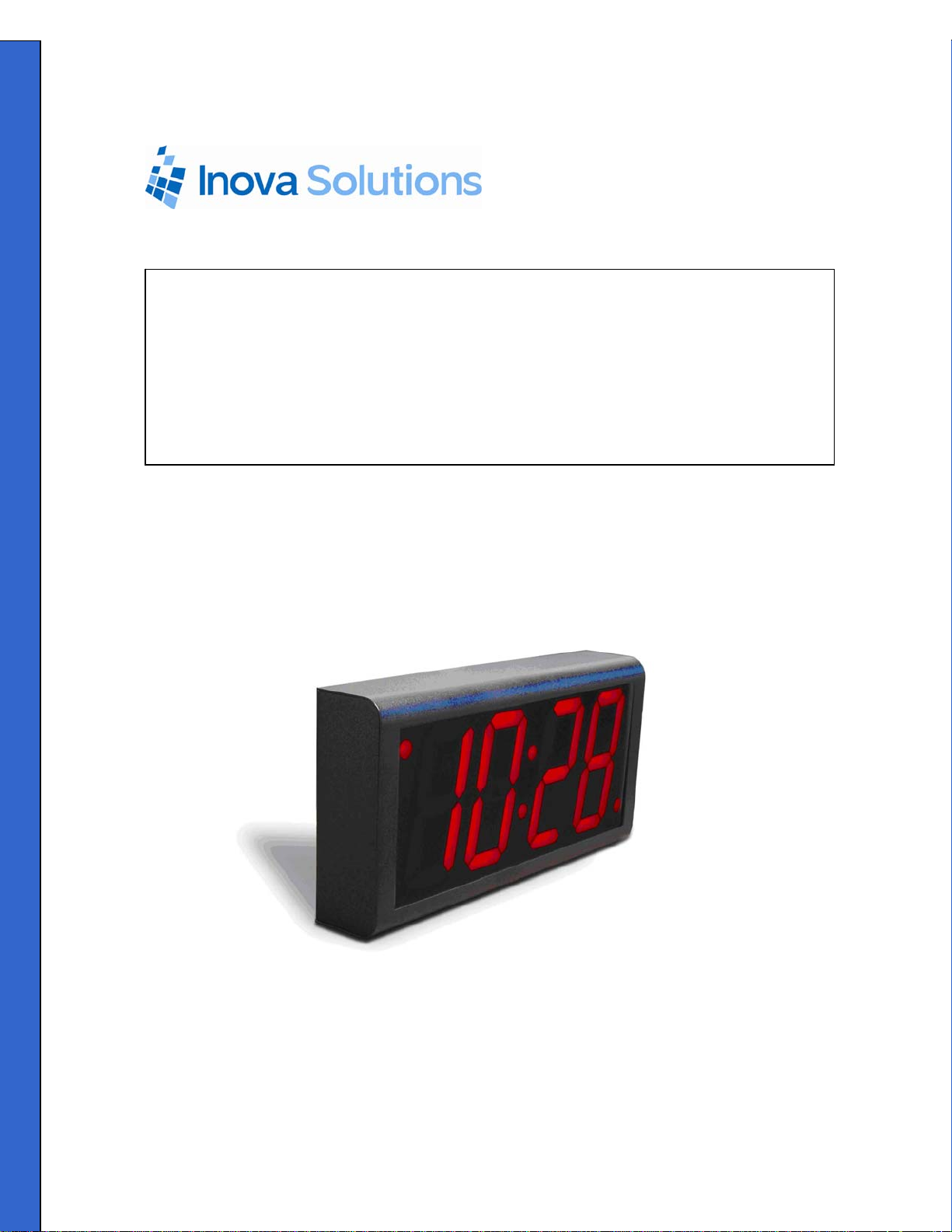
Inova OnTime
Digital Clock
Owner’s Manual
Page 2

Inova OnTime Digital Clock Owner's Manual
Inova OnTimeTM Digital Clock
Owner’s Manual
Revision 008
Inova Part#: 715412
Inova OnTime is a trademark of Inova Solutions, Inc. in the United States and/or other countries.
While reasonable efforts have been taken in the preparation of this document to insure its
accuracy, Inova Solutions, Inc. assumes no liability resulting from any errors or omissions in
this manual, or from the use of the information contained herein.
2007 Inova Solutions, Inc.
110 Avon Street
Charlottesville, VA 22902
434.817.8000
All claims based on information publicly available at time of printing. All other product or service names mentioned in this document may be
trademarks of the companies with which they are associated.
© 2007 Inova Solutions. | All rights reserved. 6.12.2007 | page ii
Page 3

Inova OnTime Digital Clock Owner's Manual
Table of Contents
Section 1: Introduction to Inova OnTime
Section 2: Safety Instructions .................................................................................. 2
Section 3: Technical Specifications ......................................................................... 3
Section 4: Unpacking and Installation..................................................................... 4
Surface Mounting .............................................................................................................................................4
Pendant Mounting – Single or Double ..................................................................................................... 5
Cantilever Mounting – Single or Double.................................................................................................. 6
Section 5: Digital Clock Configuration.................................................................... 8
Section 6: Using DHCP for Addressing and Configuration.................................... 9
Configuration Planning ..................................................................................................................................9
Creating a DHCP Configuration String....................................................................................................11
Setting a Different DHCP Option Number on a Clock .......................................................................12
TM
Digital Clocks .................................... 1
Verifying the DHCP Configuration Settings on a Clock.....................................................................12
DHCP Configuration Example for Microsoft Server............................................................................13
Section 7: Telnet Configuration............................................................................. 14
Accessing Telnet Command Line and Signing In................................................................................14
Accessing Help Commands.........................................................................................................................15
Assigning an IP Address ...............................................................................................................................15
Setting the DHCP Address..................................................................................................................................... 15
Setting the Static IP Address................................................................................................................................. 16
Specifying a Time Server ..............................................................................................................................16
Testing the Time Server Synchronization ..............................................................................................17
Selecting the Time Server ............................................................................................................................17
Selecting Time Zones ....................................................................................................................................17
Configuring Daylight Saving Time ...........................................................................................................18
Configuring 12/24 Time Format................................................................................................................18
Configuring AM/PM Indicator ....................................................................................................................18
Configuring Colons On/Off .........................................................................................................................18
All claims based on information publicly available at time of printing. All other product or service names mentioned in this document may be
trademarks of the companies with which they are associated.
© 2007 Inova Solutions. | All rights reserved. 6.12.2007 | page iii
Page 4

Inova OnTime Digital Clock Owner's Manual
Section 8: Troubleshooting.................................................................................... 19
Section 9: Recording Static IP Addresses or Host Names..................................... 20
Section 10: Maintenance......................................................................................... 21
Section 11: Product Warranty ................................................................................ 22
Repair and Return ...........................................................................................................................................22
Section 12: Glossary of Terms................................................................................ 23
Appendix A: Digital Clock Configuration ............................................................. 24
Appendix B: SNTP Basics......................................................................................... 27
Appendix C: Configuring DHCP Options for Microsoft Servers .......................... 28
All claims based on information publicly available at time of printing. All other product or service names mentioned in this document may be
trademarks of the companies with which they are associated.
© 2007 Inova Solutions. | All rights reserved. 6.12.2007 | page iv
Page 5

Inova OnTime Digital Clock Owner's Manual
Figures
Figure 1: Pendant Mounting .............................................................................................................................5
Figure 2: Cantilever Mounting.......................................................................................................................... 6
Figure 3: Mounting Kits....................................................................................................................................... 6
Tables
Table 1: Technical Specifications..................................................................................................................... 3
Table 2: Clock Configuration Methods.......................................................................................................... 8
Table 3: DHCP private option string parameters.....................................................................................11
Table 4: Examples of Common DHCP Configuration Strings…………………………………
Table 5: Configurations for Daylight Saving Time...................................................................................18
Table 6: Troubleshooting Digital Clock .......................................................................................................19
Table 7: Recording the IP Addresses or Host Names..............................................................................20
Table 8: Configuration Settings ………………………………………………… ………….
12
24
All claims based on information publicly available at time of printing. All other product or service names mentioned in this document may be
trademarks of the companies with which they are associated.
© 2007 Inova Solutions. | All rights reserved. 6.12.2007 | page v
Page 6

Inova OnTime Digital Clock Owner's Manual
Section 1: Introduction to Inova OnTimeTM Digital Clocks
The Inova OnTime
technology to the marketplace in a real-time synchronized system of clocks.
PoE is an exciting and relatively new technology that allows devices to get both power and
data over standard network cabling. It’s the same technology that powers Voice over IP
phones. Delivering both data and power over one set of wires simplifies installation, saves
space, and eliminates the need for electrical outlets at the clock mounting locations.
Additionally, the option of centralized UPS backup allows PoE devices to continue running
even in the event of a power failure.
Note: The local area network must support IEEE 802.3af Power over Ethernet in order for the
PoE clocks to operate.
This document contains:
• Safety Instructions
• Technical Specifications
• Installation Instructions
• Configuration Procedures
• Troubleshooting Solutions
• Maintenance/Warranty
TM
Digital Clock brings all the advantages of Power over Ethernet (PoE)
All claims based on information publicly available at time of printing. All other product or service names mentioned in this document may be
trademarks of the companies with which they are associated.
© 2007 Inova Solutions. | All rights reserved. 6.12.2007 | page 1
Page 7

Inova OnTime Digital Clock Owner's Manual
Section 2: Safety Instructions
Before installing or operating any OnTime Digital Clock, it’s important that you carefully read
and understand the following safety considerations.
1. To prevent personal injury, damage to the unit, or other harm, read this manual in its entirety
before installing or operating the OnTime Digital Clock.
2. Observe normal safety precautions and use appropriate safety equipment (safety glasses,
gloves, ladders, etc.) when installing this product.
3. Never install wiring during a lightning storm.
4. Never install telephone jacks in wet locations unless the jacks are specifically designed for
wet locations.
5. Be sure that mounting hardware is suitable for the mounting surface and sufficient to
support the weight of the units.
6. This product is safe when installed and operated as described in this Owner’s Manual.
7. This product is not a toy! Please keep it out of the reach of children.
8. Operation of this product in a manner inconsistent with the instructions given in this manual
may result in personal injury and/or damage to the product and will void the warranty.
9. There are no user-serviceable parts inside the unit. Attempting to open and/or alter the
product will void the warranty.
10. Do not use liquid cleaners or aerosol cleaners. Use a damp cloth for cleaning.
11. Do not use this product near water, for example, near a bathtub, wash bowl, kitchen sink, or
laundry tub, in a wet basement, or near a swimming pool.
12. Do not place this product on an unstable cart, stand, or table. The product may fall, causing
serious damage to the product or to installers.
All claims based on information publicly available at time of printing. All other product or service names mentioned in this document may be
trademarks of the companies with which they are associated.
© 2007 Inova Solutions. | All rights reserved. 6.12.2007 | page 2
Page 8

Inova OnTime Digital Clock Owner's Manual
Section 3: Technical Specifications
The OnTime Digital Clock is currently available in the models listed in the table below with
the following specifications.
Technical Specifications
Accuracy +0/-200 milliseconds
Operating Temperature 32º to 104º F (0º to 40º C)
Viewing Distance The numerals are visible to 150 feet (50 meters)
Operating Humidity 95% maximum, non-condensing
Mounting Options Surface, Pendant, Cantilever, Flush Inset, Double Sided
Certifications UL 1950, ELT Listed, CE Marked, RoHS Compliant
Power IEEE 802.3af Compliant, less than 15.4 watts, Power over Ethernet (PoE)
Network Interface 10/100 BaseT with PoE
Warranty One (1) year, returned to factory
ONT4 Models ONT6 Models
Display Face 4-Digit, Red 7-segment LEDs Display Face 6-Digit, Red 7-segment LEDs
Dimensions 12”L X 6”H X 2.2”D (30 cm X 5.6 cm) Dimensions 17.5”L X 6”H X 2.2”D (44.5 cm X 5.6 cm)
Cabinets Plastic in Black, Putty, or Off-White,
Brushed Stainless Steel
Weight Plastic Cabinet: 2 lbs (0.9kg)
Steel Cabinet: 3.8 lbs (1.7kg)
Cabinets Aluminum in Black, Putty, or Off-White,
Brushed Stainless Steel
Weight Aluminum Cabinet 2.5 lbs (1.1 kg)
Steel Cabinet 5 lbs ( 2.3 kg)
Table 1: Technical Specifications
All claims based on information publicly available at time of printing. All other product or service names mentioned in this document may be
trademarks of the companies with which they are associated.
© 2007 Inova Solutions. | All rights reserved. 6.12.2007 | page 3
Page 9

Inova OnTime Digital Clock Owner's Manual
Section 4: Unpacking and Installation
The OnTime Digital Clock arrives fully assembled in a single package. Inspect the clock and
report any damage to Inova Solutions, Inc.
Once you have removed and inspected the clock, you have several mounting options to
consider. The procedures for surface mounting, pendant mounting, and cantilever
mounting are included on the following pages.
Surface Mounting
The following is a recommended procedure for surface mounting. No mounting kit is
required.
1. Determine the clock mounting location.
2. Mark two points 10” (25.4 cm) apart, level, and centered on the data cable outlet.
3. Insert two flat-head fasteners suitable for the wall surface at the marked points and tighten.
4. Withdraw the fasteners until there is a 1/16” (.16cm) gap between the mounting surface and
the back of the fastener head.
5. Insert the data cable into the jack located at the back of the OnTime Digital Clock.
6. Position the keyhole slots located on the rear of the clock over the fastener heads.
7. Pull the clock slightly downward until the unit is seated.
All claims based on information publicly available at time of printing. All other product or service names mentioned in this document may be
trademarks of the companies with which they are associated.
© 2007 Inova Solutions. | All rights reserved. 6.12.2007 | page 4
Page 10

Inova OnTime Digital Clock Owner's Manual
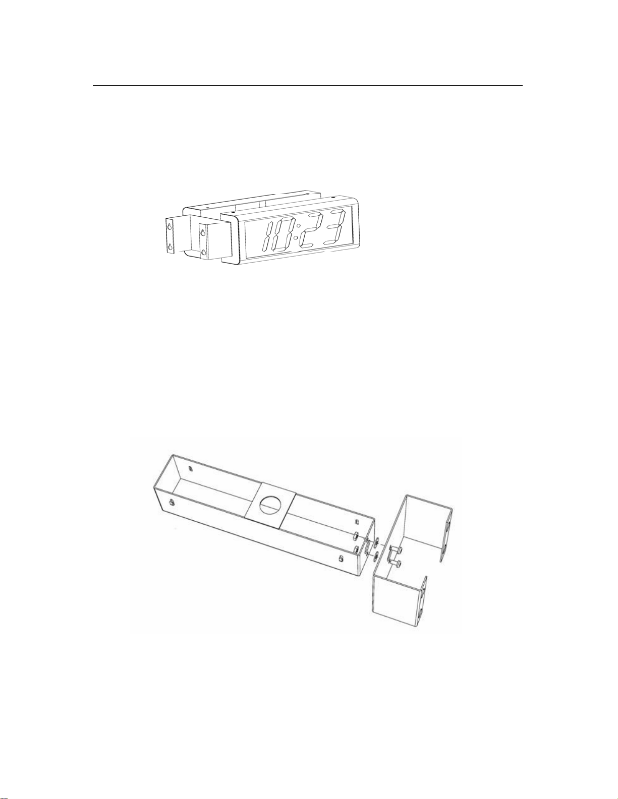
Pendant Mounting – Single or Double
The following is a recommended procedure for pendant mounting. This procedure requires
a mounting kit – Model ONTKIT - and some additional hardware.
Figure 1: Pendant Mounting
1. Determine the clock mounting location.
The illustration above suggests a recommended mounting means for a pendant mount of
one or more OnTime Digital Clock. Supplement the ONTKIT with two suitable locknuts and a
length of ¾ “ 1.905 cm) pipe or conduit.
2. Mark the location where the clock assembly is to be mounted, making sure that the
mounting means is located beneath the data cable outlet.
3. Assemble and tighten the locknuts and pipe length as shown above.
4. Insert about 10 to 12 inches (30 cm) of data cable through the center hole of the mounting
kit. Securely attach the mounting means using fasteners suitable for the surface.
5. Lift an OnTime Digital Clock into position and insert the data cable into the jack located on
the back of the clock.
6. Position the keyhole slots located on the rear of the clock over the mounting tabs.
7. Pull the clock slightly downwards until the unit is seated.
8. Repeat for the second clock if two clocks are being installed back-to-back.
All claims based on information publicly available at time of printing. All other product or service names mentioned in this document may be
trademarks of the companies with which they are associated.
© 2007 Inova Solutions. | All rights reserved. 6.12.2007 | page 5
Page 11
Inova OnTime Digital Clock Owner's Manual
Cantilever Mounting – Single or Double
The following is a recommended procedure for cantilever mounting. This procedure
requires a mounting kit, Model ONTKIT.
Figure 2: Cantilever Mounting
1. Determine the clock mounting location.
2. Using the template provided, mark the location where the clock is to be mounted, making
sure the center is located over the data cable outlet.
3. Join the Ethernet Clock Mount (Inova p/n 714755) and the Ethernet Clock Cantilever Wall
Mount (Inova p/n 714756) using a #2 Phillips screwdriver and a 3/8” (.952 cm) wrench. Make
sure that the 2 washers are fitted between the Clock Mount and the Cantilever Wall Mount.
Refer to the illustration below.
Figure 3 - Mounting Kits
4. Insert 10 to 12 inches (30 cm) of data cable through the center hole of the mounting unit.
All claims based on information publicly available at time of printing. All other product or service names mentioned in this document may be
trademarks of the companies with which they are associated.
© 2007 Inova Solutions. | All rights reserved. 6.12.2007 | page 6
Page 12

Inova OnTime Digital Clock Owner's Manual
5. Securely attach the mounting unit to the wall using fasteners suitable for the wall surface.
6. Lift the clock into place and insert the data cable into the jack located on the back of the
clock.
7. Position the keyhole slots located on the rear of the clock over the mounting tabs on the
clock mount.
8. Pull the clock slightly downwards until the unit is seated.
9. Repeat for the second clock if two clocks are being installed back-to-back.
All claims based on information publicly available at time of printing. All other product or service names mentioned in this document may be
trademarks of the companies with which they are associated.
© 2007 Inova Solutions. | All rights reserved. 6.12.2007 | page 7
Page 13

Inova OnTime Digital Clock Owner's Manual
Section 5: Digital Clock Configuration
Once a clock is installed, the next step is to confirm or set the configuration . Though there
are a number of settings you can confirm or change on a clock, you should concentrate on
four configuration items initially. These include:
• An IP address so that the clock can communicate on the network.
• A network time server so that the clock knows which computer to synchronize its time with.
• The local time zone so that the clock can display the correct local time.
• The Daylight Saving Time (DST) rule so that the clock can automatically adapt to local DST.
Before working with these settings, however, you have to consider which configuration
method to use. You have three options:
Configuration Method Description Reference
The recommended method is to
assign both the IP address and all
options via a DHCP configuration
string.
The second method is to assign an
IP address via DHCP and set
individual configuration options
via a telnet session.
The third method is to assign an IP
address and individual
configuration options via a telnet
session.
This method is the only way to address and
configure a group of clocks without requiring a
telnet session into each clock. Clocks are factory
set with DHCP enabled.
Using this method, the DHCP server is set up
with a clock configuration string. Clocks will
automatically request the configuration string
when they request an IP address.
Clocks are factory set with DHCP enabled. The
options may be set using telnet commands.
Use telnet commands to assign both a static IP
address and the appropriate configuration
options.
Table 2: Clock Configuration Methods
To learn more about the recommended method of using the DHCP configuration string,
continue with Section 6. To learn more about using a telnet session exclusively, refer to
Section 7.
Section 6
Section 7
Section 7
All claims based on information publicly available at time of printing. All other product or service names mentioned in this document may be
trademarks of the companies with which they are associated.
© 2007 Inova Solutions. | All rights reserved. 6.12.2007 | page 8
Page 14

Inova OnTime Digital Clock Owner's Manual
Section 6: Using DHCP for Addressing and Configuration
Configuration Planning
The OnTime Digital Clock allows you to benefit from a DHCP option that automatically
configures five settings when a clock is booted up. This option reduces the work required to
configure multiple clocks, because, rather than configuring each individual clock though a
telnet session, the configuration is done one time at the DHCP server. Note that because the
DHCP server is likely controlled by your network administrator or IT group, you will want to
discuss this topic with them and enlist their help in configuring the DHCP server.
The clocks are factory configured to request DHCP service, and further, to request a
configuration string using DHCP private option 230. This DHCP configuration option can be
used to establish these required settings:
The DHCP configuration option can be used to set these required settings:
• Time Server - A network time server so that the clock knows which computer to
synchronize its time with.
• Time Zone - The local time zone so that the clock can display the correct local
time.
• Daylight Saving Time - The DST rule so that the clock can automatically adapt to
local DST.
The DHCP configuration option can also be used to establish these optional settings:
• 24 hour – The factory default is 12 hour time. Set this option if 24 hour time is
desired.
• Show/hide colon – The factory default is to show a colon as a separator between
hours and minutes. In 24 hour time mode, some users prefer to turn the colon
separator off (for example, to show 2301 instead of 23:01).
The recommended practice is to load the configuration string into the DHCP server and then
try it with one clock by re-booting the clock. As the clock boots, it will send out a query
requesting a response from the DHCP server that includes an IP address, subnet mask,
gateway information, etc., as well as the configuration string associated with private option
230. When the DHCP server replies to the clock with the command line associated with
option 230, the clock will automatically use the command line contents to establish its
settings. Once you are confident that the one clock is properly configured using these
settings, you can then feel free to add additional clocks to the network knowing that they
will automatically receive the proper configuration settings as well.
All claims based on information publicly available at time of printing. All other product or service names mentioned in this document may be
trademarks of the companies with which they are associated.
© 2007 Inova Solutions. | All rights reserved. 6.12.2007 | page 9
Page 15

Inova OnTime Digital Clock Owner's Manual
Here are some things to keep in mind as you set up and use DHCP private option 230:
• A clock must be re-booted to request a new configuration string from the DHCP
server. The clock does not automatically request a new configuration string at the
expiration of the DHCP lease interval.
• If private option 230 is not configured on the DHCP server, this does not cause an
error condition on the clock. Rather, the clock will receive an IP address from the
DHCP server in the usual fashion but the clock’s settings for Time Server, Time
Zone, DST, etc. will not change.
• If private option 230 is already in use for another purpose on the DHCP server, it
should not interfere with the operation of the clocks. However, in order to use the
DHCP configuration feature, the clock must be set (via a telnet session) to request
a different private option – e.g., private option 231. See Setting a Different
DHCP Option Number on a Clock on page 12 for additional information.
All claims based on information publicly available at time of printing. All other product or service names mentioned in this document may be
trademarks of the companies with which they are associated.
© 2007 Inova Solutions. | All rights reserved. 6.12.2007 | page 10
Page 16

Inova OnTime Digital Clock Owner's Manual
Creating a DHCP Configuration String
The following table describes the five options that can be used in a configuration string
when establishing a private DHCP server option for automatically configuring the clock. The
format used is option name=option value, with the options separated by semicolons in the
configuration string. This string is added to the DHCP server, as described in the next
section. (See Table 4 for example configuration strings).
Option
Name
timeserver
timezone
dst
24hour true, false, t, f
Option
Value
SNTP Time
Server name
or IP address
hh:mm time
offset
none, [rule
specification]
Configuration
Setting
SNTP Time Server
(sntp –h
command)
Timezone offset
(timezone
command)
Daylight Saving
Time
(dst command)
Clock hours
display mode
(display -t
command)
Description
Sets the SNTP Time server Host Name or IP
address to use for time synchronization. If a Host
Name is used, then the DHCP server must also
provide a DNS server to use to resolve the Host
Name.
Sets the number of hours and minutes to offset
from UTC time when displaying time. This can be
negative. The minutes (:mm) are optional.
• none - Disable the Daylight Saving Time
adjustment.
• Other values parsed based on the DST
rule format. See the dst command for
more information, the format is 8
numbers in the order: startDOW startDay
startMonth startTime endDOW endDay
endMonth endTime
If true the clock uses 24hour (military) time format
and disables the AM/PM light, otherwise it uses
12hour time format and enables the AM/PM light.
Clock colon
display mode
showcolon true, false, t, f
(display -c
command)
Table 3: DHCP Private Option String Parameters
If true the colon separator between the hours and
minutes is lit.
Table 4 on the next page contains examples of the configuration strings.
All claims based on information publicly available at time of printing. All other product or service names mentioned in this document may be
trademarks of the companies with which they are associated.
© 2007 Inova Solutions. | All rights reserved. 6.12.2007 | page 11
Page 17

Inova OnTime Digital Clock Owner's Manual
Command Description
timeserver=ntp.inovasolutions.com;
timezone=-5;dst=-1 8 2 2 1 1 10 2
timeserver=10.1.128.1; timezone=0; dst= 1 -1
2 1 1 -1 9 1
timeserver=10.1.128.1; showcolon=true ;
24hour = true ; timezone=-5;dst=-1 8 2 2 1 1
10 2
• Sets the time server to
ntp.inovasolutions.com.
• Sets the time zone to Eastern Standard
Time (-5 hours from UTC)
• Enables DST for US 2007 rules.
• Sets the time server to IP Address
10.1.128.1.
• Sets the time zone for Western
European Time
• Enables DST for EU 2007 rules.
• Sets the time server to IP Address
10.1.128.1.
• Enables the colon display and sets the
clock to 24 hour mode.
• Sets the time zone to Eastern Standard
Time (-5)
• Enables DST for US 2007 rules.
Table 4: Examples of Common DHCP Configuration Strings
Setting a Different DHCP Option Number on a Clock
You do not have to use DHCP configuration option 230 for the clocks. You can also create
custom options using a different option number. Suppose private option 230 is already in
use on your DHCP server and you want to configure your clock to use another private option
instead, for example option 231. The ipconfig command can be used to set a different DHCP
option number on the clock or to disable this feature altogether. The ipconfig command is
defined in Appendix A.
Verifying the DHCP Configuration Settings on a Clock
The dhcpconfig telnet command lists all the configuration settings that were retrieved by
the clock from the DHCP server and that are currently in effect. If an error arises while
parsing the DHCP options received from the server, the error will be shown in the
command’s output. Look on the next page for an example.
All claims based on information publicly available at time of printing. All other product or service names mentioned in this document may be
trademarks of the companies with which they are associated.
© 2007 Inova Solutions. | All rights reserved. 6.12.2007 | page 12
Page 18

Inova OnTime Digital Clock Owner's Manual
The dhcpconfig command output below shows the settings that were received from the
DHCP server using the configuration string in the first row of Table 4 above.
dhcpconfig
Using Option Code 230 for DHCP based Clock Configuration.
The following DHCP based configuration settings are in use:
Time Server : ntp.inovasolutions.com
Time Zone : -5
DST Rule : -1 8 2 2 1 1 10 2
DHCP Configuration Example for Microsoft Server
Appendix C contains an example of how to configure private options on a Microsoft DHCP
server, such as the one that is bundled with Windows 2003 Server. It is for reference only. It
is assumed that skilled IT personnel are the only people authorized to edit DHCP server
settings.
All claims based on information publicly available at time of printing. All other product or service names mentioned in this document may be
trademarks of the companies with which they are associated.
© 2007 Inova Solutions. | All rights reserved. 6.12.2007 | page 13
Page 19

Inova OnTime Digital Clock Owner's Manual
Section 7: Telnet Configuration
You may also choose to configure the digital clock using a telnet session instead of using
DHCP. This section describes the telnet commands used in an initial setup. These
commands include:
• Accessing Help Commands
• Assigning an IP Address
• Specifying a Time Server
• Testing the Time Server Synchronization
• Selecting the Time Server
• Selecting Time Zones
• Configuring Daylight Saving Time
• Configuring 12/24 Time Format
• Configuring AM/PM Indicator
• Configuring Colons On/Off
A complete list of these telnet commands plus other optional commands can be found in
Appendix A.
Accessing Telnet Command Line and Signing In
To configure your PoE clock, you must know its IP address. If you are uncertain of its
address, see Page 24 in Appendix A for information on how to identify it. You can then log
into the clock from a PC using telnet:
1. From the Windows Start Menu, choose Run.
2. When the Run window appears, type cmd and press Enter.
3. When the command line window appears, type a telnet command like this where you
substitute for xxx.xxx.xxx.xxx the known IP address on your network of the PoE clock:
telnet xxx.xxx.xxx.xxx
The clock login prompt appears:
Digital Clock
Welcome to Clock Version xxx
iclock login:
Additionally, the clock’s service light begins to blink.
4. Enter the clock’s login ID (iclock).
All claims based on information publicly available at time of printing. All other product or service names mentioned in this document may be
trademarks of the companies with which they are associated.
© 2007 Inova Solutions. | All rights reserved. 6.12.2007 | page 14
Page 20

Inova OnTime Digital Clock Owner's Manual
The clock’s password prompt appears:
iclock password:
5. Enter the clock’s password (the default is timely).
The clock’s telnet prompt appears:
iclock />
You are now ready to set configuration using the telnet commands.
Accessing Help Commands
For help with a specific telnet command, at the prompt, you have two options:
help or ? along with the command.
For example, to see help for the display option:
display ? or help display
Assigning an IP Address
There are two options for assigning an IP Address to each OnTime Digital Clock:
• DHCP Address [Factory Default]
• Static IP Address
Setting the DHCP Address
The factory default is DHCP. When connected to the network, the clock will request DHCP
service. The letters DHCP may be displayed briefly on the screen. If the DHCP message
remains in place, then DHCP service is not available.
All claims based on information publicly available at time of printing. All other product or service names mentioned in this document may be
trademarks of the companies with which they are associated.
© 2007 Inova Solutions. | All rights reserved. 6.12.2007 | page 15
Page 21

Inova OnTime Digital Clock Owner's Manual
Setting the Static IP Address
To enter a fixed IP address into your clock’s firmware, start a telnet session with the clock
and the use the following command option:
ipconfig -a xxx.xxx.xxx.xxx -m yyy.yyy.yyy.yyy -g
zzz.zzz.zzz.zzz
where
and
xxx.xxx.xxx.xxx is the IP address, yyy.yyy.yyy.yyy is the subnet mask,
zzz.zzz.zzz.zzz is the gateway address. All fields must be provided.
Note: Your IT staff must authorize and provide a static IP address to prevent operational
problems which might occur if that address is applied to another device on the network.
Specifying a Time Server
The network time server on the LAN, WAN, or on the internet may be specified by IP Address
or by Host Name.
• Specifying by IP address is typically only safe if the address of the server is under your
IP Group’s control. When specifying time servers on the internet, use the Host Name.
• Specifying by Host Name requires that a DNS server is accessible to the clock:
• If IP addressing is static, the DNS servers must be identified and configured
as well.
• If IP addressing is via DHCP, the DNS servers are typically already
automatically configured (do not over configure!)
The process for specifying a time server is the same for both Host Name and IP Address.
1. Log into the OnTime Digital Clock.
2. At the prompt, type: sntp –h.
3. Press the spacebar.
4. Enter the Host Name of the time server – e.g.
5. Press the Enter key.
All claims based on information publicly available at time of printing. All other product or service names mentioned in this document may be
trademarks of the companies with which they are associated.
© 2007 Inova Solutions. | All rights reserved. 6.12.2007 | page 16
Page 22

Inova OnTime Digital Clock Owner's Manual
Testing the Time Server Synchronization
It is always a good idea to test the synchronization between the clock and the time server. To
do that, perform these steps:
1. At the prompt, type: sntp -s (Be sure there is a space between sntp and -s)
2. Press the Enter key.
The clock displays SNTP settings and immediately attempts a synchronization with the
specified host (either the Host Name of the time server on your network or with an outside
time standard).
Selecting the Time Server
The default time server is set to ntp. inovasolutions.com. In general, this setting should be
changed to an internal time server under IT control. There is more information on NTP, SNTP
and time server selection at
www.buy inova.com under the support tab.
Selecting Time Zones
Coordinated Universal Time (UTC) is a time standard based on the time at zero degrees
longitude (also known as Greenwich Mean Time or GMT). Time zones around the world are
expressed as positive or negative offsets from UTC. The default time zone setting for the
clock is UTC -5, which is the time zone for (GMT -5) Eastern Time (US & Canada). You can
change this setting with the following command:
timezone –N [or] timezone N
where N=the time zone offset from UTC, -11 to 12.
Note: If you’re not sure what time zone offset to use, check the time zone value used on a
Windows PC on your network; double-click the time in the Windows service tray (in the lowerright corner of your screen) and choose the Time Zone tab.
All claims based on information publicly available at time of printing. All other product or service names mentioned in this document may be
trademarks of the companies with which they are associated.
© 2007 Inova Solutions. | All rights reserved. 6.12.2007 | page 17
Page 23

Inova OnTime Digital Clock Owner's Manual
Configuring Daylight Saving Time
The following table identifies the process for setting daylight saving time.
No Daylight Saving Time
In the U.S. and Canada Type: dst -rule -1 8 2 2 1 1 10 2
For European Daylight Saving
Time
Other locations The support web site at www.buyinova.com contains a DST
Table 5: Configurations for Daylight Saving Time
Three additional time related configuration items should also be set initially. The
commands for setting 12/24, AM/PM, and Colons On/Off are identified below.
Configuring 12/24 Time Format
display –t 24
Sets 24 hour display. Note the space before and after –t.
display –t 12
Sets 12 hour display. Note the space before and after –t.
Configuring AM/PM Indicator
display –p off
Turns off pm indicator. Note the space before and after –p.
Display –p on
Turns on pm indicator. Note the space before and after –p.
Configuring Colons On/Off
display –c off
Turns off colons. Note the space before and after –c.
display –c on
Turns on colons. Note the space before and after –c.
All claims based on information publicly available at time of printing. All other product or service names mentioned in this document may be
trademarks of the companies with which they are associated.
Type the command to disable DST: dst –none
Press the Enter key.
Press the Enter key.
Note: dst –raw will work in all clock versions. dst -rule works
with Versions 1.1 or 1.2.
Type: dst -rule 1 -1 2 1 1 -1 9 1
Press the Enter key.
calculator which can compute the correct DST configurations
string for you location. Obtain the correct string and enter it
with the dst –rule command.
© 2007 Inova Solutions. | All rights reserved. 6.12.2007 | page 18
Page 24

Inova OnTime Digital Clock Owner's Manual
Section 8: Troubleshooting
The following table contains several trouble conditions you may encounter with the OnTime
Digital Clock and the recommended actions to take to correct the problem.
Note: The up-to-date troubleshooting help is available in the FAQ at www.buyinova.com under
the support tab.
Condition Solution
Clock Face Dark
Clock Shows Incorrect Time
DHCP Message on Clock Face
Service Light Blinking
Service Light On
Determine the IP Address of a
Clock
Clock showing ------ No Time Server/Time Server down
Other Problems Refer to the FAQ at www.buyinova.com under the support tab.
Table 6: Troubleshooting OnTime Digital Clock
1. Verify that an Ethernet PoE power injector is present (if required)
and is operating.
2. Reboot the clock by disconnecting the data cable, counting to five,
and reconnecting the cable.
1. If the Service Light is illuminated (see below).
2. If the minutes past the hour are correct, verify the Time Zone and
Daylight Saving Time settings.
1. The clock has failed to receive an IP address from the DHCP server.
2. Contact your IT group responsible for DHCP service.
Note: that the clock is reachable through its fixed link-local address
for diagnostic or re-configuration purposes. The link-local address is
169.254.0.100
The service light is located at the bottom right of the clock face.
1. There is an active telnet configuration session in progress on the
clock.
The service light is located at the bottom right of the clock face.
1. Reboot the clock to verify that it properly receives a DHCP address.
2. Verify that the SNTP server configuration is valid as the service light
will also be illuminated after several missed updates. Refer to the
“Testing the Time Server Synchronization” section in Section 7: Telnet
Configurations
If the IP Address of each clock has not been recorded during installation,
it is suggested to follow this power cycle procedure.
1. Lift UP gently on the unit to free the keyholes at the rear of the clock
from the mounting hardware.
2. Disconnect the network cable from the clock in question and count to
five.
3. Replace the network cable and watch the face of the Inova Digital
Clock.
It will display its IP address as it boots.
All claims based on information publicly available at time of printing. All other product or service names mentioned in this document may be
trademarks of the companies with which they are associated.
© 2007 Inova Solutions. | All rights reserved. 6.12.2007 | page 19
Page 25

Inova OnTime Digital Clock Owner's Manual
Section 9: Recording Static IP Addresses or Host Names
In order to make the management of your OnTime Digital Clock system as easy as possible,
Inova recommends that you record the IP Address/Host Name for each unit in the system as
it is installed. Refer to Appendix A to see how to determine the IP Address of a clock.
A table is provided below for recording each IP Address/Host Name as the unit is installed.
Record the Clock ID in column 1, the location in column 2, and the IP Address/Host Name in
column 3.
The Host Name will be visible in most DHCP servers. It should describe the location so that
the IP Address of a particular clock will be easy to locate by matching up the Host Name.
CLOCK ID# LOCATION
Table 7: Recording IP Addresses or Host Names
IP ADDRESS/HOST NAME
All claims based on information publicly available at time of printing. All other product or service names mentioned in this document may be
trademarks of the companies with which they are associated.
© 2007 Inova Solutions. | All rights reserved. 6.12.2007 | page 20
Page 26

Inova OnTime Digital Clock Owner's Manual
Section 10: Maintenance
The OnTime Digital Clock requires little or no maintenance.
• A minimum of one daily visual inspection at the beginning of each shift is
recommended for the entire system.
• With the exception of periodic cleaning of the clock faces with a soft clean cloth, no
routine maintenance of the system is required.
Note: Attempting to repair/replace the Digital Clock internal components may void the
warranty on that unit. Instead, during the warranty period, failed units should be sent to Inova
for repair, and the failed unit replaced with a spare.
After the warranty period, you may send the OnTime Digital Clock units to Inova under RMA
procedures for repair. See the next section for more information.
All claims based on information publicly available at time of printing. All other product or service names mentioned in this document may be
trademarks of the companies with which they are associated.
© 2007 Inova Solutions. | All rights reserved. 6.12.2007 | page 21
Page 27

Inova OnTime Digital Clock Owner's Manual
Section 11: Product Warranty
Inova Solutions warrants the Inova Digital Clock to be free from defects in material and
workmanship during a one-year period. The Warranty begins on the date the unit is shipped
from Inova Solutions.
Inova Solutions liability under this Warranty is limited to repairing or replacing, at Inova
Solutions’ option, the defective equipment and providing upgrade version changes
for firmware. In cases of repair, the product must be returned to an authorized Service
Center.
This Warranty does not apply if repairs are required due to acts of nature beyond Inova
Solutions’ control (such as, but not limited to, lightning strikes and power surges), misuse,
damage, neglect, or if repairs/modifications have been made or attempted by anyone other
than personnel authorized by Inova Solutions.
IN NO EVENT WILL INOVA SOLUTIONS BE LIABLE FOR ANY INDIRECT, SPECIAL, INCIDENTAL,
OR CONSEQUENTIAL DAMAGES FROM THE SALE OR USE OF THIS PRODUCT. THIS
DISCLAIMER APPLIES BOTH DURING AND AFTER THE TERM OF THE WARRANTY. INOVA
SOLUTIONS DISCLAIMS LIABILITY FOR ANY IMPLIED WARRANTIES, INCLUDING IMPLIED
WARRANTIES OF MERCHANTABILITY AND FITNESS FOR A SPECIFIC PURPOSE.
Repair and Return
To obtain service under this Warranty, contact Inova Solutions at (888) 637-1079 or at the
address below during the Warranty period to receive a Return Material Authorization (RMA)
number and shipping instructions. Then ship the product believed to be defective,
transportation prepaid, for inspection.
Inova Solutions will not be responsible for dismounting and remounting of Inova Digital
Clocks, for unauthorized returns, or for returns that do not list the RMA number and quantity
returned on a packing list attached in plain view on the outside of the shipping container.
Ship to:
Inova Solutions
110 Avon Street
Charlottesville, VA 22902
Attn: RMA XXXXXXX
Typical equipment repair or replacement time is seven (7) business days, plus shipping
times. One-way shipping is the Customer's responsibility. Inova Solutions will return ship
the equipment by the same means it was received.
All claims based on information publicly available at time of printing. All other product or service names mentioned in this document may be
trademarks of the companies with which they are associated.
© 2007 Inova Solutions. | All rights reserved. 6.12.2007 | page 22
Page 28

Inova OnTime Digital Clock Owner's Manual
Section 12: Glossary of Terms
Cantilever
Mount
DHCP Dynamic Host Configuration Protocol (DHCP) is a communications protocol that lets
DNS The Domain Name System (DNS) is the way that Internet domain names are located and
Flush Inset This model may be backplate-mounted to a customer-supplied enclosure.
GMT Greenwich Mean Time, since replaced with UTC, the world time standard.
Host Name Unique identifier for a device on a TCP/IP network. For example: 3rdFlrConfRm
IP Address Unique identifier for a device on a TCP/IP network. For example: 11.15.55.233
Pendant
Mount
This is a wall mount to the left or right side of the OnTime Digital Clock unit, illustrated in
Section 4, requiring the Digital Clock Mounting Kit, Inova Part Number ONTKIT.
network administrators manage and automate the assignment of IP Addresses on an
organization's network.
translated into IP Addresses. A domain name is a meaningful and easy-to-remember
"handle" for an Internet address.
This is a ceiling mount, illustrated in Section 4, requiring the Digital Clock Mounting Kit,
Inova Part Number ONTKIT.
PoE Power over Ethernet, IEEE 802.3af
SNTP Simple Network Time Protocol
Surface
Mount
Telnet
UTC or
GMT
This is a simple flat wall mount identified in Section 4. No mounting kit is required.
A network protocol and a software program that allows you to remotely access the
command console of a computer over a network.
Universal Coordinated Time, formerly Greenwich Mean Time is the World Time Standard.
UTC is, by definition, the same at every point on Earth. Local times are indicated by offsets
from UTC.
All claims based on information publicly available at time of printing. All other product or service names mentioned in this document may be
trademarks of the companies with which they are associated.
© 2007 Inova Solutions. | All rights reserved. 6.12.2007 | page 23
Page 29

Inova OnTime Digital Clock Owner's Manual
Appendix A: Digital Clock Configuration
This section summarizes the configuration options available with the Digital Clock.
Condition Solution
Get help for clock commands
? or help To see a list of all the telnet command options for which help is
available.
To see help for a particular command option, type the command option help
followed by ?. For example, to see help for the display option:
display ? or help display
Determine the IP Address of a
Clock
Display the configuration settings
for clock
View or change the Daylight
Saving Time (DST) setting
If the IP Address of each clock has not been recorded during installation, it is
suggested to follow this procedure.
1. Lift UP gently on the unit to free the keyholes at the rear of the clock
from the mounting hardware.
2. Disconnect the network cable from the clock in question and count to
five.
Replace the network cable and watch the face of the clock. It will display its IP
address as it boots.
config Display all configuration parameters except those sent by the DHCP
server. Use the DHCP config command to view these superseding options
No Daylight Saving Time - Type the command to disable DST: dst –none
Press the Enter key.
US and Canada - Type: dst -rule -1 8 2 2 1 1 10 2
Press the Enter key.
European - Type: dst -rule 1 -1 2 1 1 -1 9 1
Press the Enter key.
Other Locations – The support web site at
calculator which can compute the correct DST configurations string for you
location. Obtain the correct string and enter it with the dst –rule
command.
www.buyinova.com contains a DST
All claims based on information publicly available at time of printing. All other product or service names mentioned in this document may be
trademarks of the companies with which they are associated.
© 2007 Inova Solutions. | All rights reserved. 6.12.2007 | page 24
Page 30

Inova OnTime Digital Clock Owner's Manual
View or Configure Clock’s IP
settings
ipconfig To view clock’s current IP settings:
ipconfig -o xxx Use DHCP to lease an IP address and request a configuration
string where xxx is the private option number. Factory default is 230.
ipconfig -o - will disable the configuration portion of the DHCP process.
ipconfig -d Use DCHP to lease an IP address and retrieve network settings.:
ipconfig -a xxx.xxx.xxx.xxx -m yyy.yyy.yyy.yyy -g zzz.zzz.zzz.zzz
where xxx.xxx.xxx.xxx is the IP address, yyy.yyy.yyy.yyy is the subnet mask, and
zzz.zzz.zzz.zzz is the gateway address. (All the information is ignored if DHCP is
enabled.) - To configure a static IP address:
ipconfig -h hostname where hostname is the new hostname. - To change the
hostname of the clock.
View current SNTP settings or
Change Time Server setting
sntp To view the current time server and other SNTP settings:
sntp -h xxx.xxx.xxx.xxx where xxx.xxx.xxx.xxx is the hostname or IP address of
the desired time server. - To change the time server the clock synchs with.
sntp -s To trigger an immediate SNTP time synchronization.
Change the Time Zone
Specifying a Time Server
Testing the Time Server
Synchronization
Verifying DHCP Configuration
settings
Display all Address Resolution
Protocol (ARP) cache entries
timezone To view the clock’s current time zone setting.
timezone –N or timezone N To change the clock’s time zone setting, (don’t
use a + sign for positive values) where N = the desired time zone offset in the
range -11 to 12.
For example, to set the time zone for (GMT -5) Eastern Time (US & Canada), you
would use: timezone -5
Note: If you’re not sure what time zone offset to use, check the time zone
value used on a Windows PC on your network; double-click on the time in the
Windows service tray (in the lower-right corner of your screen) and choose the
Time Zone tab.
sntp –h hostname where hostname is the hostname of the time server.
sntp -s
dhcpconfig Lists the option settings received from a DHCP server (for
verification purposes only).
arp
All claims based on information publicly available at time of printing. All other product or service names mentioned in this document may be
trademarks of the companies with which they are associated.
© 2007 Inova Solutions. | All rights reserved. 6.12.2007 | page 25
Page 31

Inova OnTime Digital Clock Owner's Manual
View log on session screen or
enable/disable logging
List all TCP connections
Log To view the log on the session screen.
log on|off To enable/disable logging.
When logging is enabled, by typing “log on”, the idle session time out feature
is disabled.
netstat
Display info to diagnose DNS
problem with SNTP server
Configuring the 12/24 Time
Format
Configuring the AM/PM Indicator
Configuring Colons On/Off
Update clock firmware
Reboot the clock
nslookup SNTPServerName where SNTPServerName is the hostname or IP
address of an SNTP server.
display –t 24 Sets 24 hour display. Note the space before and after –t
display –t 12 Sets 12 hour display. Note the space before and after –t
display –p off Turns off pm indicator. Note the space before and after –p
display –p on Turns on pm indicator. Note the space before and after –p
display –c off Turns off colons. Note the space before and after –c
display –c on Turns on colons. Note the space before and after –c
Refer to FAQ at www.buyinova.com under the support tab.
reboot
Table 8: Configuration Commands
All claims based on information publicly available at time of printing. All other product or service names mentioned in this document may be
trademarks of the companies with which they are associated.
© 2007 Inova Solutions. | All rights reserved. 6.12.2007 | page 26
Page 32

Inova OnTime Digital Clock Owner's Manual
Appendix B: SNTP Basics
SNTP is an acronym for Simple Network Time Protocol. SNTP is widely used to
synchronize time on computers. Certain computers within a LAN or on the internet have the
responsibility of maintaining accurate time in order to provide a time standard for the
network. Your network administrator should be able to direct you to an appropriate local
time server for your environment.
The OnTime Digital Clock must be configured with the network location of a time server.
The default time server is an internet time server operated by Inova.
Periodically, a computer transmits a time query in order to synchronize its time with a time
server. Every two hours the OnTime Digital Clock transmits a time query to the time server
and the time server replies. With the reply in hand, the clock calculates the time offset, or
correction, that it needs to apply to its current time and then makes the update.
In the event that the time server does not reply, the OnTime Digital Clock continues to
display time while it retries the time server. After repeated unsuccessful tries, the clock
illuminates its Service Light (an LED dot at the lower right-hand side of the clock), indicating
that the displayed time is no longer synchronized.
All claims based on information publicly available at time of printing. All other product or service names mentioned in this document may be
trademarks of the companies with which they are associated.
© 2007 Inova Solutions. | All rights reserved. 6.12.2007 | page 27
Page 33

Inova OnTime Digital Clock Owner's Manual
Appendix C: Configuring DHCP Options for Microsoft Servers
This section details how to configure private options on a Microsoft DHCP server, such as the
one that is bundled with Windows 2003 Server. It is for reference only and may not
represent the specific options that you may encounter.
1. Launch the DHCP Management Console.
2. Select the DHCP server to configure.
3. Choose the Action “Set Predefined Options…”
4. Choose “Add…” a new option.
5. Set the Data type to ‘String’.
6. Use the option code that matches your clock configuration. The default option code
is 230.
All claims based on information publicly available at time of printing. All other product or service names mentioned in this document may be
trademarks of the companies with which they are associated.
© 2007 Inova Solutions. | All rights reserved. 6.12.2007 | page 28
Page 34

Inova OnTime Digital Clock Owner's Manual
7. Select either the Server Options or Scope Options and choose “Configure Options…”.
8. Select the Option in the list and select the checkbox to enable it.
9. Enter the configuration string you’ve developed for your unique operating environment and
geographic location.
All claims based on information publicly available at time of printing. All other product or service names mentioned in this document may be
trademarks of the companies with which they are associated.
© 2007 Inova Solutions. | All rights reserved. 6.12.2007 | page 29
 Loading...