


User Instructions
86BPQ00001 2006-10 (ver. 1.2)

Table of Contents
Table of Contents..........................................................................................................2
1. Introduction..............................................................................................................4
1.1 About this manual ............................................................................................4
1.2 About ProfIPAQ................................................................................................4
1.2.1 Features: ..................................................................................................4
1.3 About PROFIBUS..............................................................................................5
Part 1 .....................................................................................................................6
2 ProfIPAQ-H/-HX/-L Installation and Maintenance..........................................................6
2.1 General ...........................................................................................................6
2.1.1 CAUTION ..................................................................................................6
2.1.2 Ex installation............................................................................................6
2.1.3 Default Settings.........................................................................................6
2.2 ProfiSoft Communication...................................................................................6
2.3 Short form Data (complete data in chapter Specifications)...................................7
2.3.1 Ex Data (also see certificate and control drawings).......................................7
2.4 Identification of the transmitter: See labels on the transmitter .............................8
2.5 Installation in an encapsulation .........................................................................9
2.5.1 Ambient temperature considerations ...........................................................9
2.5.2 ProfIPAQ-H/-HX (Gas)................................................................................9
2.5.3 ProfIPAQ-H/D/-HX/D (Dust)......................................................................10
2.5.4 ProfIPAQ-L..............................................................................................11
2.6 Connections...................................................................................................12
2.6.1 Connection Diagram.................................................................................12
2.6.2 LCD-W12 ................................................................................................12
2.6.3 Ex Bus connection: ..................................................................................12
2.6.4 Ex Cable requirements: ............................................................................13
2.6.5 ProfIPAQ SmartSense (low sensor isolation detection) ................................ 13
2.6.6 ProfIPAQ Sensor Aging.............................................................................13
2.7 Specification ..................................................................................................13
2.7.1 Input RTD 2-, 3- and 4-wire connection...................................................13
2.7.2 Input Resistance...................................................................................... 13
2.7.3 Input Thermocouple ................................................................................13
2.7.4 Input Voltage ..........................................................................................14
2.7.5 Double inputs for RTD, Thermocouple and Voltage..................................... 14
2.7.6 Output....................................................................................................14
2.7.7 General data ...........................................................................................14
2.7.8 Environment conditions (also see Ex data).................................................14
2.7.9 Resolution and Accuracy ..........................................................................14
2.7.10 Accuracy Specifications for RTD and Thermocouple Input ........................... 15
2.8 Dimensions....................................................................................................15
2.8.1 ProfIPAQ-H/-HX.......................................................................................15
2.8.2 ProfIPAQ-L..............................................................................................15
2.9 Service and repair .......................................................................................... 16
2.10 Ordering information ...................................................................................... 16
2.11 Accessories....................................................................................................16
3 Control Drawings for installation guidance ..................................................................17
2

Part 2 ...................................................................................................................19
4 ProfIPAQ Software and Programming.........................................................................19
4.1 INOR PC configuration software ProfiSoft ......................................................... 19
4.1.1 Installation..............................................................................................19
4.1.2 Overview. ...............................................................................................19
4.1.3 Input configuration .................................................................................. 20
4.1.4 Device information................................................................................... 21
4.1.5 Output configuration................................................................................22
4.1.6 Download and upload configuration to/from ProfIPAQ ................................ 23
4.1.7 View temperature ....................................................................................24
4.1.8 Change address with ProfiSoft .................................................................. 24
4.1.9 Customized Linearization, Datapair............................................................25
4.1.10 Error Correction.......................................................................................26
4.1.11 Settings .................................................................................................. 27
4.1.12 Password ................................................................................................ 27
5 ProfIPAQ in a ProfiBus system ................................................................................... 28
5.1 DDL-file.........................................................................................................28
5.2 GSD-file......................................................................................................... 28
5.3 PROFIBUS/ProfIPAQ parameters......................................................................29
6 Appendix A. Parameter table ..................................................................................... 32
6.1 Function Block Analog Input............................................................................ 32
6.2 Transducer Block Temperature Device ............................................................. 32
6.3 Physical Block Transmitter...............................................................................33
7 Appendix B. PROFIBUS Cabling..................................................................................34
7.1 Shielding and grounding .................................................................................34
7.2 Termination ................................................................................................... 35
8 WARRANTY.............................................................................................................. 36
3

1. Introduction
1.1 About this manual
This manual is intended to assist in installing, operating, and maintaining ProfIPAQ
temperature transmitters with PROFIBUS-PA, and it is divided into two parts;
Part 1: ProfIPAQ-H/-HX/-L Installation and Maintenance. Here you will find
connection drawings, mechanical drawings, electrical data, guidelines for mounting into
hazardous Ex location and accessories.
and
Part 2: Software and Programming. This describes ProfiSoft, the software to configure
the ProfIPAQ transmitters via the PC serial port.
It also contains some generic PROFIBUS information. ProfIPAQ transmitters DD are
integrated into Siemens Simatic PDM version 5.1 or higher. For use with an earlier version
of Siemens Simatic PDM and other software problems using Siemens Simatic PDM, consult
Siemens user’s manual.
1.2 About ProfIPAQ
ProfIPAQ is a line of temperature transmitters from INOR, designed according to the
latest PROFIBUS-PA standard for temperature transmitters, i.e. Profile 3.0, class A & B. At
present the following versions are available:
ProfIPAQ-H in-head for non-Ex and Non-Incendive gas (Zone 2) applications.
ProfIPAQ-H/D is a dust version of ProfIPAQ-H with dust tested housing for non-Ex and NonIncendive dust (Zone 22) applications.
ProfIPAQ-HX in-head for Intrinsic safe Ex ia/ib gas applications (Zone 0 and 1),
ProfIPAQ-HX/D is a dust version of ProfIPAQ-HX with a dust tested housing for Intrinsic safe
Ex ia/ib dust applications (Zone 21) applications and
ProfIPAQ-L DIN-rail mounted for non-Ex applications.
1.2.1 Features:
• PROFIBUS PA certified communication
• Easy setup via a separate INOR communication port as an alternative to PROFIBUS
• High accuracy measurement
• Linearizes for most temperature sensors.
• Custom linearization for other type of sensors with mV and ohm output.
• Accepts two input signals making it possible to do differential measurements, average
measurement, redundancy and sensor ageing control.
• FDE (Fault Disconnect Equipment) ensures that the ProfIPAQ transmitter won’t pull down
a whole segment in a PROFIBUS net if the transmitter fails internally.
• DDL and GSD files available
• Sensor monitoring functions: sensor break, sensor short circuit, low sensor isolation
• A separate LCD-indicator can be connected to the communication port of the transmitter.
4

1.3 About PROFIBUS
PROFIBUS-PA is an all-digital, serial, two-way communication system that interconnects
field equipment such as sensors, actuators, and controllers. Power supply and output digital
signal uses the same two wires. The physical layer is described in EN 61158-2 and the
protocol in EN 50170.
For more information concerning PROFIBUS, visit the PROFIBUS organization homepage at
address www.profibus.com. There you find a lot of information about the PROFIBUS
protocol, PROFIBUS tools, PROFIBUS news, GSD and DDL’s, competence center, FAQ’s and
more and there is a lot of interesting PDF’s for downloading.
5
Part 1
2 ProfIPAQ-H/-HX/-L Installation and Maintenance
2.1 General
Electrical temperature sensors such as RTDs and thermocouples produce low-level signals
proportional to temperature. The ProfIPAQ temperature transmitter converts the analogue
sensor signal to a digital signal that is relatively insensitive to lead length and electrical
noise. This digital signal is then transmitted over the bus to the configuration device and the
control system.
The ProfIPAQ transmitter is compatible with many RTD and thermocouple sensor types as
well as potentiometer and voltage input. Figure 12 shows the correct input connections to
the sensor terminals on the transmitter.
2.1.1 CAUTION
If the sensor is installed in a high-voltage environment and a fault condition or
installation error occurs, the sensor leads and transmitter terminals could carry
lethal voltages. Use extreme caution when making contact with the leads and terminals.
2.1.2 Ex installation
For a safe installation in hazardous area the transmitter must only be installed by
qualified personnel that are familiar with the national and international laws,
regulations, directives and standards (e.g. EN50039, En 50284, IEC 60079-14 and IEC
60079-17) that apply to the installation conditions.
2.1.3 Default Settings
The ProfIPAQ transmitter has a standard configuration when it is delivered from factory.
These settings can be changed by either the ProfiSoft software, via Simatic PDM system or
via any other system using the ProfIPAQ DDL.
Default Settings:
Address: 126
Input signal: Pt100, 4-wire
Output signal: °C
Filter: 0 s
Sensor Monitoring: Off
2.2 ProfiSoft Communication
Communication to ProfIPAQ via ProfiSoft and INOR Communication cable must
NOT be performed unless the area where the transmitter is located is known to
be non-hazardous. When installed in hazardous area always use the PROFIBUS
communication to change settings.
6

2.3 Short form Data (complete data in chapter Specifications)
Power supply 9 – 32 VDC
Isolation Input/Output 1500 VAC
Output ProfIbus PA Profile v. 3.0 Class A&B
Operating temperature ProfIPAQ-H/-HX -40 - +85 °C / -40 - +185 °F
ProfIPAQ-L -20 - +70 °C / -4 - +158 °F
2.3.1 Ex Data (also see certificate and control drawings)
ProfIPAQ-H / -H/D ProfIPAQ-HX / -HX/D
ATEX Approval
Gas II 3G Ex nL IIC T4-T6 II 1G Ex ia IIC T4-T6
Dust II 3GD Ex nL T 100°C II 1G/2D Ex ia IIC T 100°C
ProfIPAQ-H/ -H/D is intended to be connected to a standard power supply (Class 2) with
maximum supply voltage to the transmitter of 30 VDC or a FNICO power supply / Segment
coupler, mounted outside the hazardous area. The data for the transmitter is:
Bus-port (connector 6 and 7) Sensor port (1- 5) Comm.port
Ui = Vmax : 30 VDC Uo = Voc : 3,3 VDC Ui = Vmax : 8,0 VDC
Ii = Imax : no limit Io = Isc : 0,4 mA Ii = Imax : 450 mA
Pi = Pmax : no limit Po = Pt : 6,5 mW Pi = Pmax : 0,8 W
Ci : 1 nF Co = Ca : 500 µF Ci : 10 nF
Li : 10 µH Lo = La : 375 mH Li : 1 µH
For the ambient temperature:
T6: -40°C < Ta < +60°C / -40°F < Ta < +140°F
T5: -40°C < Ta < +75°C / -40°F < Ta < +167°F
T4: -40°C < Ta < +85°C / -40°F < Ta < +185°F
Dust: -30°C < Ta < +80°C / -22°F < Ta < +176°F
ProfIPAQ-HX / -HX/D is intended to be connected to a certified intrinsic safe power
supply / Segment coupler with FISCO data, mounted outside the hazardous area. The data
for the transmitter is:
Bus-port (connector 6 and 7)
Ui = Vmax : 17,5 VDC Uo = Voc : 17,5 VDC Ui = Vmax : 8,0 VDC
Ii = Imax : 380 mA Io = Isc : 56 mA Ii = Imax : 450 mA
Pi = Pmax : 5,32 W Po = Pt : 244 mW Pi = Pmax : 0,8 W
Ci : 1 nF Co = Ca : 166 nF Ci : 10 nF
Li : 10 µH Lo = La : 6 mH Li : 1 µH
For the ambient temperature:
T6: -40°C < Ta < +45°C / -40°F < Ta < +113°F
T5: -40°C < Ta < +60°C / -40°F < Ta < +140°F
T4: -40°C < Ta < +85°C / -40°F < Ta < +185°F
Dust: -30°C < Ta < +80°C / -22°F < Ta < +176°F
Sensor port (1- 5) Comm.port
7

2.4 Identification of the transmitter: See labels on the transmitter
Figure 1 Label 1 and 2 on peripheral of the transmitter ProfIPAQ-H 70PPH00001
Figure 2 Label 1 and 2 on peripheral of the transmitter ProfIPAQ-HX 70PPHX0001
Part no
Serial no (production date, Nyyww)
Figure 3 Label 1 and 2 on enclosure of the transmitter ProfIPAQ-H/Dxy 70PPHD0xy1 (e.g. 70PPHD0111)
Figure 4 Label 1 and 2 on enclosure of the transmitter ProfIPAQ-HXDxy 70PPHXDxy1 (e.g. 70PPHXD111)
Figure 5 Label 1 and 2 on enclosure of the transmitter ProfIPAQ-L 70PPL00001
Part no
Serial no (production
date, Nyyww)
8
2.5 Installation in an encapsulation
2.5.1 Ambient temperature considerations
The ProfIPAQ-H / -H/D / -HX / -HX/D transmitter is designed to operate within specifications
for ambient temperatures between –40 and 85 °C (–40 and 185 °F), also see ambient
temperatures depending on temperature class and Gas- or Dust-installation in section 2.3.1,
Ex data. Heat from the process is transferred via the thermowell to the transmitter housing.
If the expected process temperature is near or beyond specification limits, this may rise the
temperature in the transmitter housing (encapsulation) above specified ambient
temperature. Always verify that the temperature where the transmitter is mounted is not
above the specified limit. One way to reduce heat transfer via the thermowell is to increase
the length of the thermowell or to move the transmitter housing away from the heat source.
The same safety measures can be used when the temperature is below the specified
minimum temperature.
2.5.2 ProfIPAQ-H/-HX (Gas)
The transmitter may be mounted in a temperature sensor housing, in a box or on a DIN
rail. It is recommended to use INOR mounting accessories, see 2.11, Accessories.
For non-Ex application, a housing with IP 54 is recommended. Most temperature housings
fulfill this requirement.
For Ex n application (non-incendive, Zone 2, Category 3G) ProfIPAQ-H in a housing with at
least IP 54 is needed. The enclosure must fulfill the requirements of EN 60079-0 and EN
60079-15 regarding impact and IP degree, which easiest is achieved by using certified
enclosures, e.g. the housings approved together with ProfIPAQ-H/D / -HX/D.
For applications requiring installation into Zone 0 (Category 1G) or Zone 1 (Category 2G)
ProfIPAQ-HX is used, installed in an appropriate housing with an ingress protection of at
least IP20.
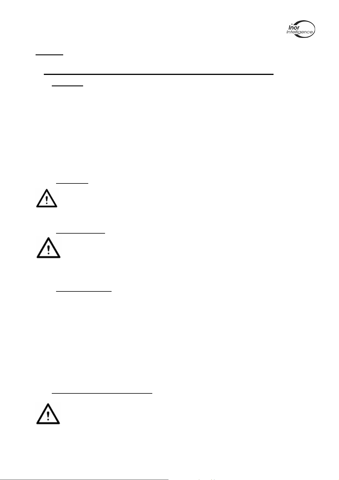
1 M4 Screw, special for ProfIPAQ-H/-HX
2 Spring
3 Locking washer
4 Sensor wires
5 Sensor protection tube
Figure 6 Mounting with Standard Mounting kit 70ADA00017
9
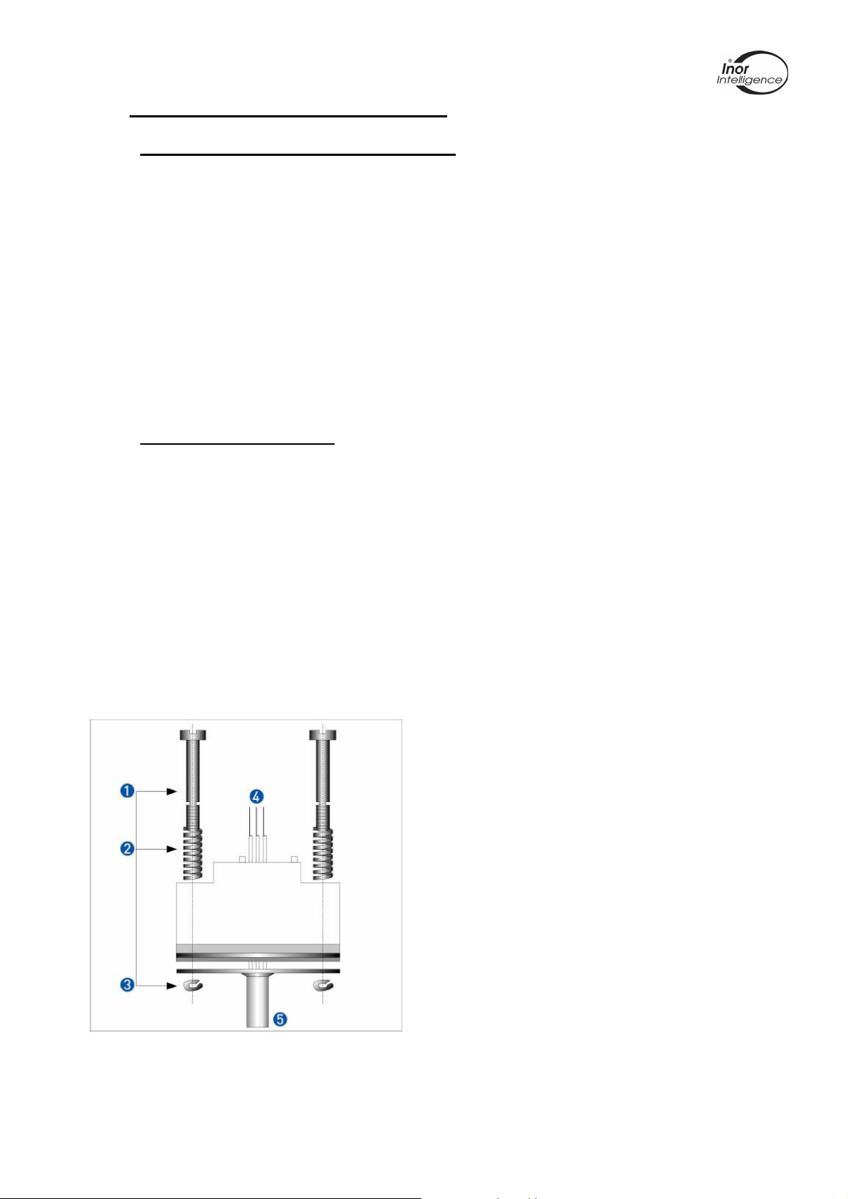
2.5.3 ProfIPAQ-H/D/-HX/D (Dust)
ProfIPAQ-HX/Dxy and ProfIPAQ-H/Dxy – D indicates it is a dust version with dust tight
connection head.
x indicates type of connection head: y indicates process entry:
x=1 INOR Connection head BI y=1 M24x1,5
x=2 INOR Connection head BS y=2 G ½”
x=3 INOR Connection head DANX (GR-A/BL) y=3 NPT ½”
Figure 7 Connection head BI Figure 8 Connection head BS
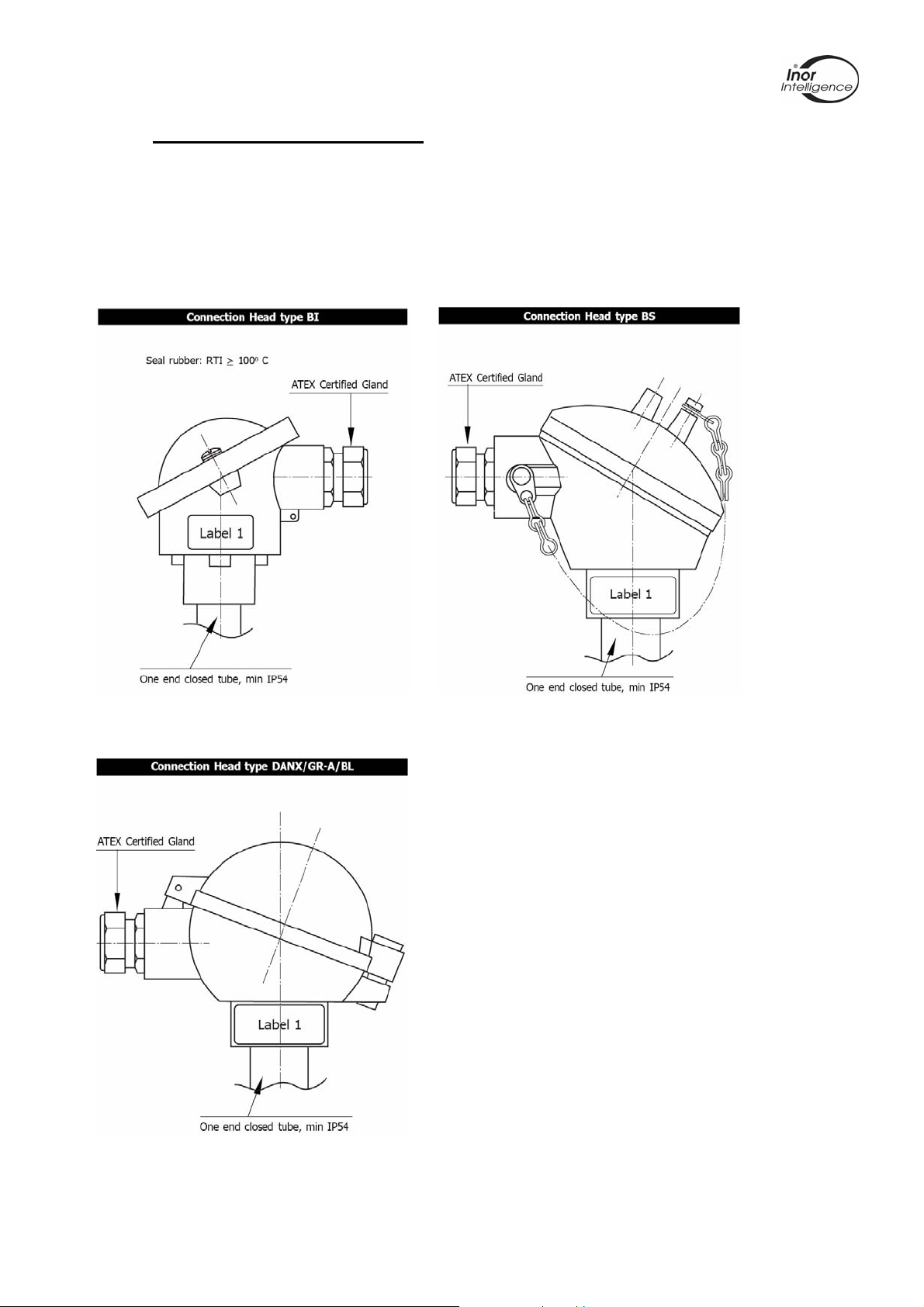
For dust-applications Category 2D (Zone
21) ProfIPAQ-HX/Dxy with at least IP 65 is
needed. Make sure the correct gasket is
used. Cable entries and blanking
elements, suitably Ex certified and
correctly installed, shall be used.
For dust-applications Category 3D (Zone
22) ProfIPAQ-H/Dxy with IP 54 is used.
Cable entries and blanking elements,
suitably Ex certified and correctly installed,
shall be used.
Figure 9 Connection head DANX
10
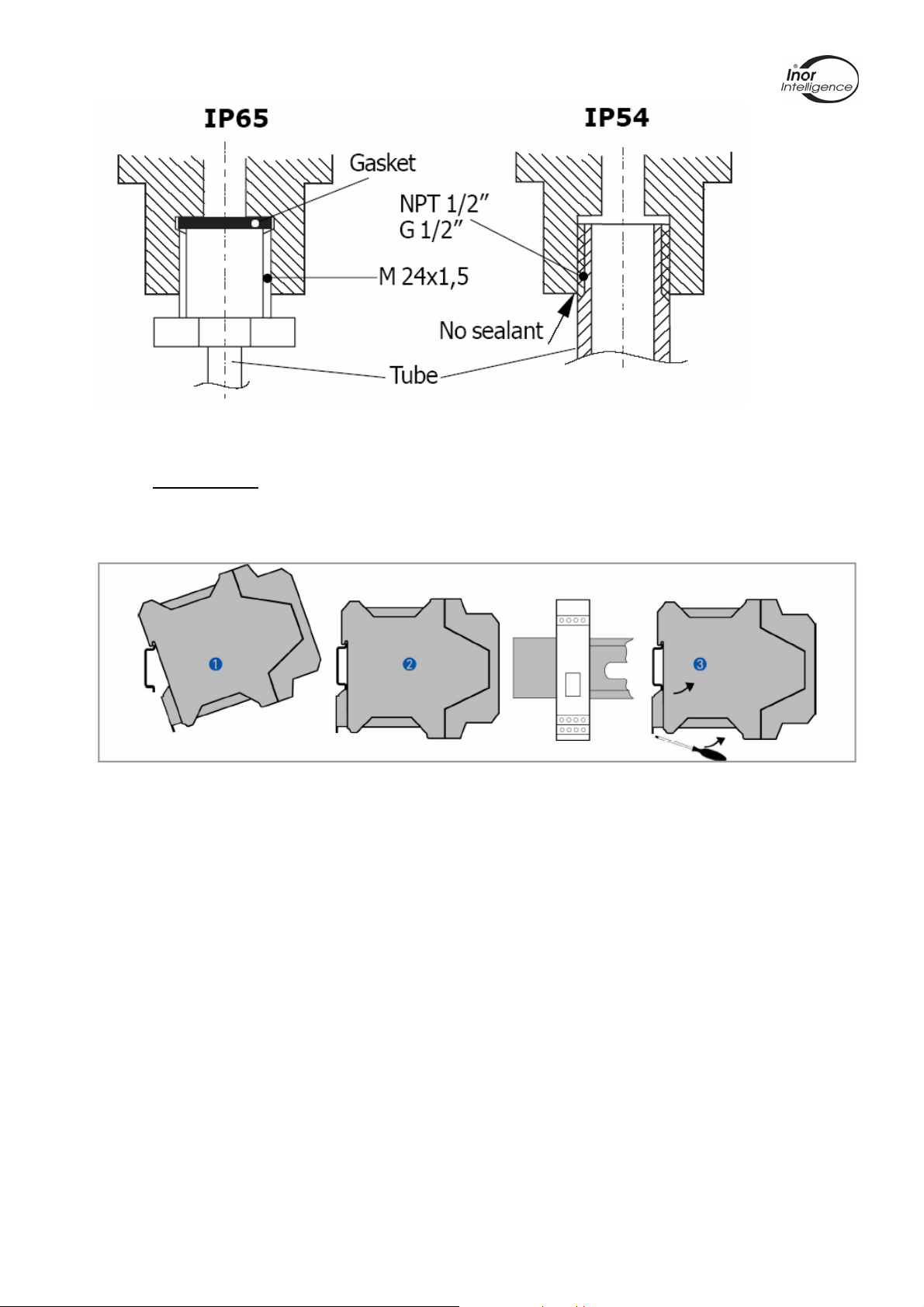
Figure 10 Connection head Sealing
2.5.4 ProfIPAQ-L
The ProfIPAQ-L transmitter is intended for mounting on a 35 mm DIN Rail and must not
be placed in Ex Hazardous area.
Figure 11 ProfIPAQ-L rail mounding and demounting
1 Place the transmitter on upper part of the rail
2 Press the transmitter down until it hangs on to the rail
3 To remove the transmitter, use a screw driver to loosen the hook from the lower
rail part and bend gently the transmitter upwards
11
 Loading...