

INOR IPAQ-R530, IPAQ-C530 Operating Manual

aHa
bndb
HHa
Handndb
IPAQ C530/R530
ndbooooooookkkk
Smart 2-wire universal transmitter
®
with HART
The documentation is only complete when used in combination with the relevant
documentation for the sensor.
7 and NFC technology
© INOR 04/2018 - 4006524701 - MA IPAQ 530 en

:
IMPRINT
:::::::::::::::::::::::::::::::::::::::
2
www.inor.com 04/2018 - 4006524701 - MA IPAQ 530 en

IPAQ C530/R530
CONTENTS
1 Safety instructions 5
1.1 Intended use ..................................................................................................................... 5
1.2 Certifications .................................................................................................................... 6
1.2.1 EC directive compliance ......................................................................................................... 6
1.2.2 Ex approvals............................................................................................................................ 6
1.3 Safety instructions from the manufacturer ..................................................................... 7
1.3.1 Copyright and data protection ................................................................................................ 7
1.3.2 Disclaimer............................................................................................................................... 7
1.3.3 Product liability and warranty ................................................................................................ 8
1.3.4 Information concerning the documentation........................................................................... 8
1.3.5 Warnings and symbols used................................................................................................... 9
1.4 Safety instructions for the operator................................................................................. 9
2 Device description 10
2.1 General description ........................................................................................................10
2.2 Nameplate ...................................................................................................................... 11
2.3 Versioning per NAMUR NE53......................................................................................... 12
2.4 Scope of delivery............................................................................................................. 12
3 Installation 13
3.1 In-head transmitter........................................................................................................13
3.2 Rail mounting kit for in-head transmitters.................................................................... 14
3.3 Rail-mount transmitter .................................................................................................. 15
4 Electrical connections 16
4.1 Safety instructions.......................................................................................................... 16
4.2 Electrical connections of in-head transmitter............................................................... 17
4.3 Connection diagram of in-head transmitter.................................................................. 18
4.4 Connection diagram of in-head transmitter (intrinsically safe).................................... 19
4.5 Electrical connections of rail-mount transmitter.......................................................... 20
4.6 Connection diagram of rail-mount transmitter............................................................. 21
4.7 Connection diagram of rail-mount transmitter (intrinsically safe)............................... 21
4.8 Cable length.................................................................................................................... 22
5 Operation 23
5.1 NFC configuration and logging ...................................................................................... 23
5.2 HART
5.3 Point-to-point connection analog / digital mode ........................................................... 24
5.4 Multi-drop connection .................................................................................................... 25
5.5 Factory settings for configuration.................................................................................. 26
5.6 Configuration with ConSoft ............................................................................................ 27
5.7 Configuration with a hand held communicator FC 475 ................................................. 30
5.8 Device management software........................................................................................ 30
®
networks ............................................................................................................ 24
www.inor.com04/2018 - 4006524701 - MA IPAQ 530 en
3

CONTENTS
IPAQ C530/R530
5.9 Configuration with PACTware ........................................................................................ 31
®
5.10 Current output and HART
dynamic/device variables ................................................ 31
5.11 Diagnostic information according to NAMUR NE 107 ................................................. 32
5.12 Factory default settings................................................................................................ 36
5.13 Sensor error monitoring .............................................................................................. 36
5.14 System or sensor error correction .............................................................................. 36
6 Service 37
6.1 Accessory parts .............................................................................................................. 37
6.2 Spare parts availability...................................................................................................37
6.3 Availability of services .................................................................................................... 37
6.4 Disposal .......................................................................................................................... 37
7 Technical data 38
7.1 Measuring principles...................................................................................................... 38
7.1.1 Resistance temperature sensor ........................................................................................... 38
7.1.2 Thermocouples ..................................................................................................................... 39
7.2 Technical data................................................................................................................. 40
7.3 Dimensions..................................................................................................................... 45
7.4 Temperature data for areas with potentially explosive atmospheres .......................... 46
7.5 Output load diagram....................................................................................................... 47
7.6 Electrical data for outputs and inputs............................................................................ 48
7.7 RTD and T/C accuracy table ........................................................................................... 49
8 Appendix 51
8.1 Installation and control drawing .................................................................................... 51
9 Notes 53
4
www.inor.com 04/2018 - 4006524701 - MA IPAQ 530 en

IPAQ C530/R530
1.1 Intended use
The IPAQ 530 transmitter is an universal HART®-compatible 2-wire transmitter designed for
temperature measurements and intended to be used in industrial environments.
• Temperature measurements with resistance thermometers
• Temperature measurements with thermocouples
• Voltage measurements in a range up to 1000 mV
• Resistance measurement up to 10 kΩ
• Measurements with potentiometers
The transmitters are configured from a PC by using the ConSoft software and a transmitter
configuration kit (USB connection), by a HART
software, e.g. PactWare, or by a Smartphone with built in NFC support
DANGER!
Responsibility for the correct use of the devices with special regard to suitability, intended use
and the field of application lies solely with the operator. To avoid any kind of incorrect use, also
note the information in the chapter "Device description".
SAFETY INSTRUCTIONS
®
-configurator, by a HART®-modem and a suitable
1
DANGER!
The transmitters do not contain any serviceable parts inside. Any substitution of components
may impair the intrinsic safety of the versions with an Ex approval. Always send defective devices
to the manufacturer or the local distributor for repair or exchange. If this is the case, attach a
clear description of the malfunction for warranty claims.
The manufacturer is not liable for any damage resulting from improper use or use for other than
the intended purpose. To avoid any kind of incorrect use, also note the information in the chapter
"Device description"!
CAUTION!
Responsibility for the use of the measuring devices with regard to suitability, intended use and
corrosion resistance of the used materials against the measured fluid lies solely with the
operator.
This device is a Group 1, Class A device as specified within CISPR11:2009. It is intended for use in
industrial environment. There may be potential difficulties in ensuring electromagnetic
compatibility in other environments, due to conducted as well as radiated disturbances.
www.inor.com04/2018 - 4006524701 - MA IPAQ 530 en
5

1
SAFETY INSTRUCTIONS
1.2 Certifications
1.2.1 EC directive compliance
CE marking
The device fulfils all applicable statutory requirements of the following EC directives:
• EMC Directive 2014/30/EU, harmonized standards EN 61326-1 and EN 61326-2-3
• Devices for use in hazardous areas: ATEX Directive 2014/34/EU, harmonized standards
• CE Directive 93/68/EC
• RoHS Directive 2011/65/EU, harmonized standard EN 50581:2012.
The manufacturer certifies successful testing of the product by applying the CE marking.
1.2.2 Ex approvals
IPAQ C530/R530
C530X (intrinsically safe)
ATEX KIWA 17ATEX0053 X II 1G Ex ia IIC T6...T4 Ga
IECEx IECEx KIWA 17.0027X Ex ia IIC T6...T4 Ga
R530X (intrinsically safe)
ATEX KIWA 17ATEX0055 X II 1G Ex ia IIC T6...T4 Ga
IECEx IECEx KIWA 17.0029X Ex ia IIC T6...T4 Ga
See also “Specific Conditions of Use" in the Ex certificates in the download area of the
manufacturer's website
6
www.inor.com 04/2018 - 4006524701 - MA IPAQ 530 en

IPAQ C530/R530
1.3 Safety instructions from the manufacturer
1.3.1 Copyright and data protection
The contents of this document have been created with great care. Nevertheless, we provide no
guarantee that the contents are correct, complete or up-to-date.
The contents and works in this document are subject to copyright. Contributions from third
parties are identified as such. Reproduction, processing, dissemination and any type of use
beyond what is permitted under copyright requires written authorisation from the respective
author and/or the manufacturer.
The manufacturer tries always to observe the copyrights of others, and to draw on works created
in-house or works in the public domain.
The collection of personal data (such as names, street addresses or e-mail addresses) in the
manufacturer's documents is always on a voluntary basis whenever possible. Whenever
feasible, it is always possible to make use of the offerings and services without providing any
personal data.
SAFETY INSTRUCTIONS
1
We draw your attention to the fact that data transmission over the Internet (e.g. when
communicating by e-mail) may involve gaps in security. It is not possible to protect such data
completely against access by third parties.
We hereby expressly prohibit the use of the contact data published as part of our duty to publish
an imprint for the purpose of sending us any advertising or informational materials that we have
not expressly requested.
1.3.2 Disclaimer
The manufacturer will not be liable for any damage of any kind by using its product, including,
but not limited to direct, indirect or incidental and consequential damages.
This disclaimer does not apply in case the manufacturer has acted on purpose or with gross
negligence. In the event any applicable law does not allow such limitations on implied warranties
or the exclusion of limitation of certain damages, you may, if such law applies to you, not be
subject to some or all of the above disclaimer, exclusions or limitations.
Any product purchased from the manufacturer is warranted in accordance with the relevant
product documentation and our Terms and Conditions of Sale.
The manufacturer reserves the right to alter the content of its documents, including this
disclaimer in any way, at any time, for any reason, without prior notification, and will not be liable
in any way for possible consequences of such changes.
www.inor.com04/2018 - 4006524701 - MA IPAQ 530 en
7

1
SAFETY INSTRUCTIONS
1.3.3 Product liability and warranty
The operator shall bear responsibility for the suitability of the device for the specific purpose.
The manufacturer accepts no liability for the consequences of misuse by the operator. Improper
installation or operation of the devices (systems) will cause the warranty to be void. The
respective "Standard Terms and Conditions" which form the basis for the sales contract shall
also apply.
1.3.4 Information concerning the documentation
To prevent any injury to the user or damage to the device it is essential that you read the
information in this document and observe applicable national standards, safety requirements
and accident prevention regulations.
If this document is not in your native language and if you have any problems understanding the
text, we advise you to contact your local office for assistance. The manufacturer can not accept
responsibility for any damage or injury caused by misunderstanding of the information in this
document.
This document is provided to help you establish operating conditions, which will permit safe and
efficient use of this device. Special considerations and precautions are also described in the
document, which appear in the form of icons as shown below.
IPAQ C530/R530
8
www.inor.com 04/2018 - 4006524701 - MA IPAQ 530 en

IPAQ C530/R530
1.3.5 Warnings and symbols used
Safety warnings are indicated by the following symbols.
DANGER!
This warning refers to the immediate danger when working with electricity.
DANGER!
This warning refers to the immediate danger of burns caused by heat or hot surfaces.
DANGER!
This warning refers to the immediate danger when using this device in a hazardous atmosphere.
DANGER!
These warnings must be observed without fail. Even partial disregard of this warning can lead to
serious health problems and even death.
SAFETY INSTRUCTIONS
1
WARNING!
Disregarding this safety warning, even if only in part, poses the risk of serious health problems.
There is also the risk of damaging the device or parts of the operator's plant.
CAUTION!
Disregarding these instructions can result in damage to the device or to parts of the operator's
plant.
These instructions contain important information for the handling of the device.
LEGAL NOTICE!
This note contains information on statutory directives and standards.
• HANDLING
HANDLING
HANDLINGHANDLING
This symbol designates all instructions for actions to be carried out by the operator in the
specified sequence.
i RESULT
RESULT
RESULTRESULT
This symbol refers to all important consequences of the previous actions.
1.4 Safety instructions for the operator
WARNING!
In general, devices from the manufacturer may only be installed, commissioned, operated and
maintained by properly trained and authorized personnel.
This document is provided to help you establish operating conditions, which will permit safe and
efficient use of this device.
www.inor.com04/2018 - 4006524701 - MA IPAQ 530 en
9

2
DEVICE DESCRIPTION
2.1 General description
The IPAQ 530 is a smart, digital 2-wire universal HART®-compatible transmitter for
temperature measurements and other measurement applications in an industrial environment.
For further information about the possible measurements refer to
Configuration of the transmitter is possible with:
®
• HART
• HART
• The graphic user interface DTM.
• The third part PC software with a FSK modem for HART
• PC configuration software ConSoft with PC configuration kit ICON-X
• NFC interface in a portable device such as a smartphone.
A smartphone APP makes it possible to read, write, save and share settings directly in the
field.
7 protocol via 4…20 mA output circuit.
®
7 hand held terminal.
Intended use
®
7 communication
IPAQ C530/R530
on page 5.
The PC configuration software ConSoft is used for configuration, display and documentation. The
current ConSoft version is available for downloading on our website.
You can find configuration instructions in the ConSoft reference manual.
ConSoft is compatible with Windows XP/Vista/7/8/8.1/10.
C530 - In-head transmitter
The in-head transmitter is optionally available in an intrinsically safe version for installation in
potentially explosive areas. These devices wear the "Ex" symbol and have an approval for
mounting into classified hazardous area, Zone 0, 1 and 2.
All in-head versions are intended for installation in a DIN-B head or larger according to EN
50446 / DIN 43729. As an alternative you can also mount the in-head version on a 35 mm rail
according to EN 60715 / DIN 50022 with the help of the rail installation kit ( refer to
kit for in-head transmitters
on page 14).
Rail mounting
R530 - Rail-mount transmitter
The R530 rail-mount transmitter has the same features as the in-head version.
The rail-mount transmitter is optionally available in an intrinsically safe version for installation
into potentially explosive areas. All devices with an Ex approval wear the "Ex" symbol. The railmount transmitter is intended for installation on a 35 mm rail according to EN 60715 / DIN 50022
10
www.inor.com 04/2018 - 4006524701 - MA IPAQ 530 en

IPAQ C530/R530
2.2 Nameplate
Look at the device nameplate to ensure that the device is delivered according to your order.
The transmitter can be identified by the information on the nameplates.
Nameplate for in-head transmitter
Nameplate for in-head transmitter
Nameplate for in-head transmitterNameplate for in-head transmitter
C530X
www.inor.com
Figure 2-1: Example for round nameplate
1 Product name
2 CE marking (EC conformity)
3 Ex-relevant electrical data
4 Part number, serial number (yyww = year and week of manufacturing) and batch number
5 Printable field, sensor configuration
6 Connections
7 Manufacturer and address
0539 II 1G Ex ia IIC T6...T4 Ga
KIWA 17ATEX0053 X
IECEx KIWA 17.0027X
70C530X010
Nyyww.xxxxxx
PO ZZZZZZZZZ
1 234
RTD
DEVICE DESCRIPTION
12
T/C
PO Box 9125
SE-200 39 Malmö
+
SWEDEN
2
Ui = Vmax: 30 V
Pi = Pmax: 0.9 W
li = lmax: 100 mA
Per Ctrl. Dwg. No. 4006360501
Figure 2-2: Example for bottom nameplate
1 Electrical data for output
2 Electronic/electric device waste marking
3 Control drawing number
www.inor.com04/2018 - 4006524701 - MA IPAQ 530 en
11

2
DEVICE DESCRIPTION
Nameplate for rail-mount transmitter
Nameplate for rail-mount transmitter
Nameplate for rail-mount transmitterNameplate for rail-mount transmitter
IPAQ C530/R530
R530X
8
Per Control Dwg
No. 4006360701
www.inor.com
Figure 2-3: Example for nameplate
1 Product name
2 Part number, serial number (yyww = year and week of manufacturing) and batch number
3 Manufacturer and address
4 Printable field, sensor configuration
5 Technical data
6 Electrical data for output and input
7 Control drawing number
8 CE marking (EC conformity) and electronic/electric device waste marking
70R530X010
Nyyww.xxxxxx
PO ZZZZZZZZZ
KIWA 17ATEX0055 X
IECEx KIWA 17.0029X
0539 II 1 G Ex ia IIC T6...T4 Ga
Max. ambient 85 °C
Ui: 30 V
Ii: 100 mA
Pi: 0.9 W
Ci: 23.1 nF
Li: 20 µH
2.3 Versioning per NAMUR NE53
PO Box 9125
SE-200 39 Malmö
SWEDEN
Uo: 6.5 V
Io: 11.7 mA
Po: 19.1 mW
Co: 24 µF
Lo: 400 mH
Hardware Firmware Firmware relese
ConSoft
HART
®
Handbook
date (MM/YYYY)
7
1
1 Label located on bottom side of head mounted transmitter and on the side of rail mounted transmitter.
01.01.04
1
04/2018 3.3.7 7.6 MA IPAQ 530 R01
2.4 Scope of delivery
Inspect the packaging carefully for damages or signs of rough handling. Report damage to the
carrier and to the local office of the manufacturer.
Do a check of the packing list to make sure that you have all the elements given in the order.
Look at the device nameplate to ensure that the device is delivered according to your order.
The scope of delivery always consists of the transmitter and its documentation.
12
www.inor.com 04/2018 - 4006524701 - MA IPAQ 530 en
IPAQ C530/R530
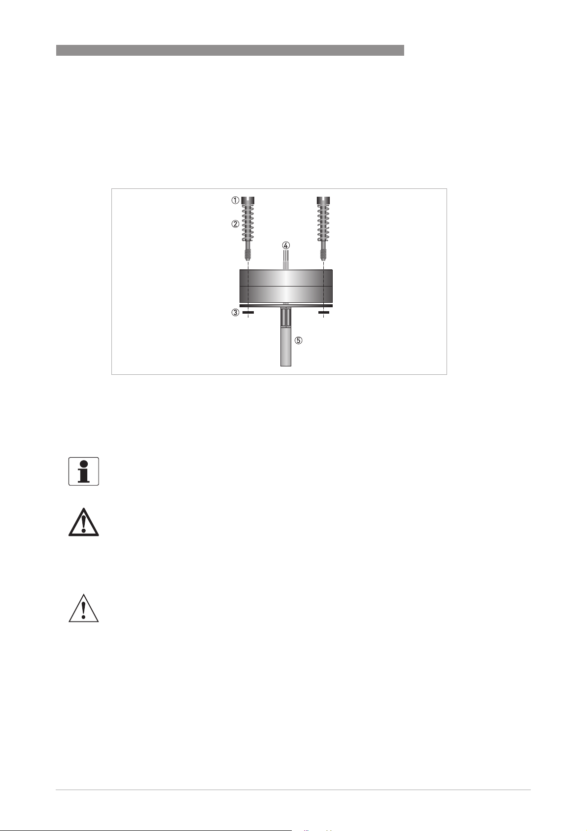
3.1 In-head transmitter
The transmitter is intended for installation in DIN B connection heads or larger. The large
Ø7 mm / 0.28 inch center hole facilitates the electrical connection of the sensor and the
installation. .
INSTALLATION
3
Figure 3-1: Connection head installation kit
1 M4 screw
2 Spring
3 Lock washer
4 Wires from the measuring inserts
5 MI Cable
The connection head installation kit does not belong to the standard scope of delivery of the
transmitter, you have to order it separately.
DANGER!
The transmitter is optionally available in an intrinsically safe version (zone 0, 1 and 2) for
installation in potentially explosive atmospheres. The intrinsically safe version must be supplied
by an intrinsically safe power supply unit or Zener barrier placed outside of the potentially
explosive zone. The Ex transmitter must be installed in a housing with the protection rating IP20
or better according to EN 60529 / IEC 60529.
WARNING!
°
The transmitter has been developed for an operating temperature of -40...+85
C/ -40°F...+185°F.
To avoid destruction or damage of the device, always assure that the operating temperature or
ambient temperature does not exceed the permissible range. The thermowell also transfer the
process temperature to the transmitter housing. If the process temperature is close to or
exceeds the maximum temperature of the transmitter, then the temperature in the transmitter
housing can rise above the maximum permissible temperature. One way to decrease the head
transfer via thermowell is to install the transmitter further away from the heat source. Inversely
similar measurements can be done if the temperature gets below specified minimum
temperature.
www.inor.com04/2018 - 4006524701 - MA IPAQ 530 en
13
3
INSTALLATION
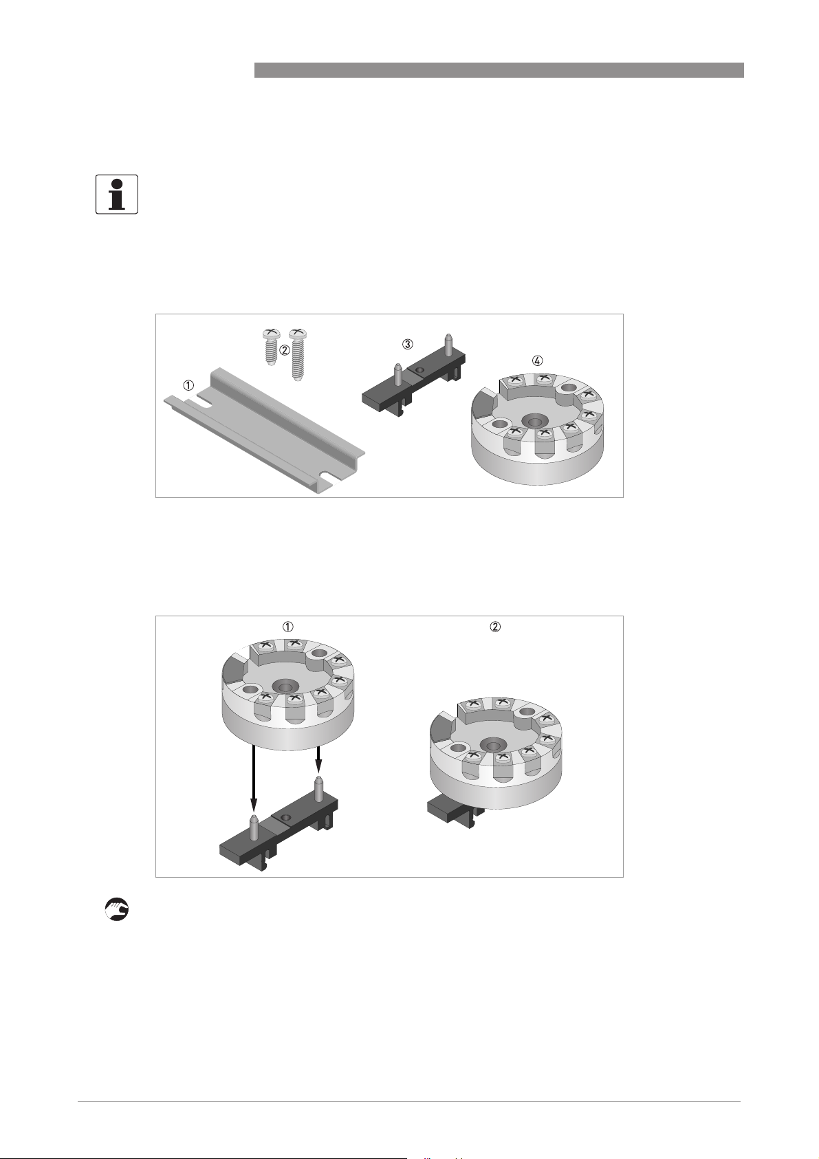
3.2 Rail mounting kit for in-head transmitters
The rail mounting kit allows to install the in-head transmitter on a rail according to EN 60715 /
DIN 50022.
The kit does not belong to the standard scope of delivery. You have to order it separately.
The screws in the kit is not to be used with this transmitter.
Rail mounting kit for in-head transmitters
IPAQ C530/R530
Figure 3-2: Rail mounting kit for in-head transmitters
1 Rail (not included in the kit)
2 Screws (not needed)
3 Clip
4 Transmitter
Installation procedure: Step 1
1 Place the transmitter on the clip.
2 Press down the transmitter until it is attached to the clip.
14
www.inor.com 04/2018 - 4006524701 - MA IPAQ 530 en

IPAQ C530/R530
Installation procedure: Step 2
1 Hook one end of the clip into the rail.
2 Push the other end down until it snaps onto the rail.
3 Release by pushing the hook, and at the same time lift the clip out of the rail.
3.3 Rail-mount transmitter
These transmitters are intended for installation on a 35 mm rail according to EN 60715 /
DIN 50022.
INSTALLATION
3
Figure 3-3: Rail installation
1 Fix the upper part of the transmitter onto the rail.
2 Press the lower part of the transmitter against the rail.
3 To remove the transmitter, bend the locking device using a small screwdriver. Carefully pull
the transmitter in the forward direction.
CAUTION!
The manufacturer has developed the R530 for an operating temperature range of
°
-40...+85
C / -40...+185°F.
To avoid destruction or damage of the device, always note the following items:
•
Assure that the operating temperature or the ambient temperature does not exceed the
permissible range.
www.inor.com04/2018 - 4006524701 - MA IPAQ 530 en
15

4
ELECTRICAL CONNECTIONS
4.1 Safety instructions
DANGER!
All work on the electrical connections may only be carried out with the power disconnected. Take
note of the voltage data on the nameplate!
DANGER!
Observe the national regulations for electrical installations!
DANGER!
The transmitter is protected against polarity reversal. No damage will occur to the device if the
polarity of the supply voltage is switched. The output will then indicate 0 mA.
DANGER!
The transmitter may be operated in areas with potentially explosive atmospheres if the voltage
supply is ensured by means of an associated apparatus.
The safety instructions for operation in potentially explosive areas must be observed.
In potentially explosive areas only Ex approved HART
In order to ensure reliable HART
length of the output circuit must be observed. For detailed information refer to Cable length on
page 22
.
IPAQ C530/R530
®
modems must be used.
®
communication with this transmitter, the maximum cable
WARNING!
Observe without fail the local occupational health and safety regulations. Any work done on the
electrical components of the measuring device may only be carried out by properly trained
specialists.
Look at the device nameplate to ensure that the device is delivered according to your order.
Check for the correct supply voltage printed on the nameplate(Applies only to the intrinsically
safe versions.)
16
www.inor.com 04/2018 - 4006524701 - MA IPAQ 530 en

IPAQ C530/R530
ELECTRICAL CONNECTIONS
4.2 Electrical connections of in-head transmitter
The input and output signals and the power supply must be connected in accordance with the
following illustrations. The transmitter is easy to install with the connection head installation kit.
To avoid measuring errors, all cables must be connected properly and the screws tightened
correctly.
RTD and potentiometer measurement
RTD and potentiometer measurement
RTD and potentiometer measurementRTD and potentiometer measurement
Pt100
Pt100…Pt1000, Ni100, Ni120, Cu10
Pt100Pt100
2-wire connection
2-wire connection
2-wire connection2-wire connection
Resistance, 2-wire connection
Resistance, 2-wire connection Resistance, 3-wire connection
Resistance, 2-wire connectionResistance, 2-wire connection
Pt1000, Ni100, Ni120, Cu10
Pt1000, Ni100, Ni120, Cu10Pt1000, Ni100, Ni120, Cu10
Pt100
Pt100…Pt1000, Ni100, Ni120, Cu10
Pt100Pt100
3-wire connection
3-wire connection
3-wire connection3-wire connection
Resistance, 3-wire connection Resistance, 4-wire connection
Resistance, 3-wire connectionResistance, 3-wire connection
Pt1000, Ni100, Ni120, Cu10
Pt1000, Ni100, Ni120, Cu10Pt1000, Ni100, Ni120, Cu10
Pt100
Pt100…Pt1000, Ni100, Ni120, Cu10
Pt100Pt100
4-wire connection
4-wire connection
4-wire connection4-wire connection
Resistance, 4-wire connection
Resistance, 4-wire connectionResistance, 4-wire connection
Pt1000, Ni100, Ni120, Cu10
Pt1000, Ni100, Ni120, Cu10Pt1000, Ni100, Ni120, Cu10
4
Potentiometer, 3-wire slide wire
Potentiometer, 3-wire slide wire
Potentiometer, 3-wire slide wirePotentiometer, 3-wire slide wire
Thermocouple and voltage measurement
Thermocouple and voltage measurement
Thermocouple and voltage measurementThermocouple and voltage measurement
Thermocouple
Thermocouple Voltage
ThermocoupleThermocouple
Voltage Thermocouple with external CJC
VoltageVoltage
Thermocouple with external CJC
Thermocouple with external CJC Thermocouple with external CJC
(Pt100)
(Pt100)
(Pt100)(Pt100)
www.inor.com04/2018 - 4006524701 - MA IPAQ 530 en
17
 Loading...