

Page 1

USER INSTRUCTIONS
Intelligent 2-wire
INT R ODUC TION
IPAQ-H is a universal and intelligent 2-wire In-head transmitter for
temperature and other measurement applications in industrial
environment.
IPAQ-HX is the Intrinsic Safe version for use in Ex-applications.
In-head Temperature
Transmitter
ATEX
The user instruction must be read prior to adjustment and/or installation.
All information subject to change without notice.
MEA SU RE OF S UCC ES S
GEN E RAL INFO RMAT I ON
The transmitter is congured from a standard IBM compatible PC
by using the IPRO software version 4.14 or later. The latest version
of IPRO can be downloaded from http://www.inor.com. When the
transmitter is set from a PC no calibration is needed.
!
The transmitter must not be connected to a computer,
when the transmitter is in hazardous area.
The transmitter is polarity protected and will not be damaged by
connecting the power supply with the wrong polarity, but the output
will be 0 mA.
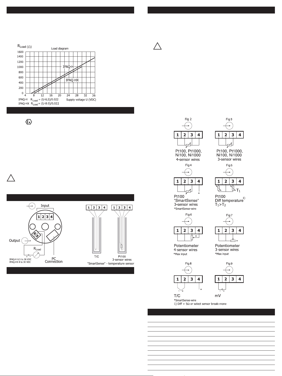
The maximum load in the output loop depends on the supply voltage,
see ”DATA shortform”
The transmitter continuosly supervises the isolation resistance in
thermocouples and 3-wire-connected Pt100 including the connection
wires. If the isolation resistance is low it causes error in the measurements and consequently a faulty ouptput. The transmitter indicates
low isolation resistance by forcing the output to a preprogrammed
value. This function requires setting by the PC-program IPRO and the
use of a temperature sensor with an extra wire.
Sensor wire check: the transmitter uses a pulsating technique to
monitor sensor break or sensor shortened to avoid measuring errors.
This pulsating signal may interfere with some electronic calibrators.
By selecting ”Sensor Break = None” in the IPRO software and
download the conguration into the transmitter the pulsating signal
is turned off.
INOR Process AB, PO Box 9125, SE-200 39 Malmö, Sweden,
Phone: +46(040)31 25 60, Fax: +46(040)31 25 70, E-mail: [email protected]
INOR Transmitter OY, Unikkotie13, FI-01300 Vantaa, Finland,
Phone:+358-9-83850219, Fax: +358-9-83850219, E-mail: jari.stadig@inor.
INOR Transmitter GmbH, Rodenbacher Chaussee 6,
Phone: +49(0)6181-582940, Fax: +49(0)6181-582944, E-mail: [email protected]
INOR Transmitter Inc, 7 Dearborn Road, Peabody, MA 01960, USA,
Fax: +1(978) 535-3882/(262) 670-9001, E-mail: [email protected]
This product should not be mixed with other kind of scrap, after usage.
DE-63457 Hanau-Wolfgang, Germany,
Phone: +1(978) 826-6900/(262) 670-9050,
www.inor.com, www.inor.se
It should be handled as an electronic/electric device.
MEA SU RE OF S UCC ES S
DIM E NSIO NS
CON F IGUR ATIO N
The IPAQ-H/HX transmitter must be powered, when you congure
the transmitter, (see ”Connections” g.1). If IPRO (the IPAQ software)
isn’t installed in your PC, install the software (follow the instructions in
”IPRO User instructions”).
For keeping the safety of the internal circuits in the
!
IPAQ-HX, always use Ex-power supply or a zener barrier
with limitations according to Ex-data and IPRO-X conguration cable when making a conguration with the transmitter
in or connected to hazardous area.
86BIQ00015 2007-06
When choosing differential temperature measuments with Pt100 be
sure to select ”sensor break” = none.
Conguration from PC is ”on-line”, that is, the transmitter can be congured while in operation if the area is known to be non-hazardous.
The output is frozen while transmission from PC to IPAQ take place.
When transfer is done the transmitter uses the new parameters.
Page 2
DAT A (sh ortf orm)
Power supply: IPAQ-H 6.5 to 36 VDC
IPAQ-HX 8 to 30 VDC
Isolation in/out: 1500 VAC
Output: 4-20 mA
Operating temperature: -40 to +50 °C (T6)
-40 to +65 °C (T5)
-40 to +85 °C (T4)
IPAQ-HX EX-DATA
Approval Demko 02 ATEX 132033
CE 0539 II 1G EEx ia IIC T4-T6
Approval FM, J.I 0D6A8.AX, CSA 2007 Certicate 1863602
Class I, Division 1, Group A, B, C and D
Control Drawing 3-7851
Output (current loop)
U
Ii ≤ 100 mA
i
≤ 30 VDC
Pi ≤ 900 mW
Li ~ 0 mH
Ci ~ 0 nF
IPAQ-HX must be powered from an intrinsic safe power
!
supply or zener barrier, placed outside the hazardous area.
Input (sensor)
Uo ≤ 30 VDC
Io ≤ 25 mA
Po ≤ 188 mW
Lo ~ 50 mH
C
o
~ 66 nF
INS T ALLA TION
IPAQ-H/HX are designed to t inside connection heads type DIN B
or larger.
The larger center hole, dia. 7 mm/0.28 inch (see ”Dimensions”),
facilitates the pulling through of the sensor leads or an insert tube,
greatly simplifying the mounting procedure.
IPAQ-HX must be installed in an enclosure having
!
an Ingress Protection suitable for the actual use
but at least IP20.
If IPAQ-HX is mounted in a housing (head) made of light
metals and installed in hazardous area make sure the content
of magnesium (Mg) in the light metal is less than 6%.
If IPAQ-HX is mounted in a housing which is isolated from
ground and can be charged to an ignition capable level, then
the housing shall be electrostatically grounded when installed
in hazardous area.
Connect input, output and power supply acc. to g. 1-9.
A convinient way to install the transmitter is to use the INOR mounting kits for in-head and DIN rail mounting, (see ”Ordering table”). In
order to minimize measuring errors make sure the connecting screws
are tightened enough.
CON N ECT I ONS
Fig 1.
Fig 10.
LIM I TED WARR ANTY
INOR Process AB, or any other afliated company within the Inor Group (hereinafter jointly referred to as
”Inor”), hereby warrants that the Product will be free from defects in materials or workmanship for a period
of ve (5) years from the date of delivery (”Limited Warranty”). This Limited Warranty is limited to repair
or replacement at Inor’s option and is effective only for the rst end-user of the Product. Upon receipt of
a warranty claim, Inor shall respond within a reasonable time period as to its decision concerning:
1 Whether Inor acknowledges its responsibility for any asserted defect in
materials or workmanship; and, if so,
2 the appropriate cause of action to be taken (i.e. whether a defective
product should be replaced or repaired by Inor).
This Limited Warranty applies only if the Product:
1 is installed according to the instructions furnished by Inor;
2 is connected to a proper power supply;
3 is not misused or abused; and
4 there is no evidence of tampering, mishandling, neglect, accidenta damage, modication
or repair without the approval of Inor or damage done to the Product by anyone other
than Inor.
This Limited Warranty is provided by Inor and contains the only express warranty provided.
INOR SPECIFICALLY DISCLAIMS ANY EXPRESS WARRANTY NOT PROVIDED HEREIN AND
ANY IMPLIED WARRANTY, GUARANTEE OR REPRESENTATION AS TO SUITABILITY FOR
ANY PARTICULAR PURPOSE, PERFORMANCE, QUALITY AND ABSENCE OF ANY HIDDEN
DEFECTS, AND ANY REMEDY FOR BREACH OF CONTRACT, WHICH BUT FOR THIS PROVISION, MIGHT ARISE BY IMPLICATION, OPERATION OF LAW, CUSTOM OF TRADE OR
COURSE OF DEALING, INCLUDING IMPLIED WARRANTIES OF MER-CHANTABILITY AND
FITNESS FOR A PARTICULAR PURPOSE. EXCEPT AS PROVIDED HEREIN, INOR FURTHER
DISCLAIMS ANY RESPONSIBILITY FOR LOSSES, EXPENSES, INCONVENIENCES, SPECIAL,
DIRECT, SECONDARY OR CONSEQUENTIAL DAMAGES ARISING FROM OWNERSHIP OR
USE OF THE PRODUCT.
Products that are covered by the Limited Warranty will either be repaired or replaced at the option of
Inor. Customer pays freight to Inor, and Inor will pay the return freight by post or other “normal” way of
transport. If any other type of return freight is requested, customer pays the whole return cost.
ORDERING TABLE
Item Part No.
IPAQ-H, isolated 70IPH00001
IPAQ-HX, isolated (ATEX) 70IPHX0001
IPAQ-HX, isolated (FM, CSA) 70IPHX1001
Software and cable
Conguration kit IPRO with cables 70CFG00092
Accessories
Surface mounting box 70ADA00008
Rail mounting box 70ADA00009
Head mounting kit 70ADA00012
Rail mounting kit 70ADA00013
 Loading...