

Page 1
INTRODUCTION
USER INSTRUCTIONS
Universal 1- & 2-channel
Programmable 2-wire
Transmitter
ATEX
The user instruction must be read prior to adjustment and/or installation.
All information subject to change without notice.
MEA S URE O F S U CCE S S
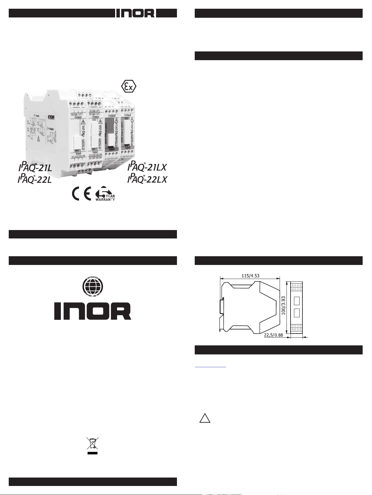
IPAQ-22LX is an Intrinsic Safe, 2-channel universal and intelligent
2-wire rail-mounted transmitter for temperature and other low-level
measurement Ex-applications. IPAQ-21LX = 1 channel.
IPAQ-21L/-22L are the non-Intrinsic Safe versions for use in safe areas.
GENERAL INFORMATION
The transmitter is congured from a standard IBM compatible PC by using
the IPRO software version 4.31 or later. The latest version of IPRO can
be downloaded from http://www.inor.com. When the transmitter is
set from a PC no calibration is needed.
When calibrating/conguring the IPAQ-21LX/-22LX ATEX
certied version of IPRO-X cable must be used.
Please observe that the 2 channels have separate conguration
outlets so put the IPRO-X plug in outlet 1 or 2 depending on which
channel to congure.
The transmitter is polarity protected for the power supply and will not
be damaged by connecting with the wrong polarity, but the output
will be 0 mA.
The maximum load in the output loop depends on the supply voltage,
see ”DATA shortform”
”Isolation input/output/PC” mentioned in the data sheet, indicates IS
galvanic isolation like an isolating barrier. Therefore ordinary power
supplies with Um < 250 VAC can be used with IPAQ-21LX/-22LX.
Sensor wire check: the transmitter uses a pulsating technique to monitor sensor
break or sensor shortened to avoid measuring errors. This pulsating signal may
interfere with some electronic calibrators. By selecting ”Sensor Break = None”
in the IPRO software and download the conguration into the transmitter the
pulsating signal is turned off.
INOR Process AB, PO Box 9125, SE-200 39 Malmö, Sweden,
Phone: +46-40-31 25 60, Fax: +46-40-31 25 70, E-mail: [email protected]
INOR Transmitter OY, Unikkotie 13, FI-01300 Vantaa, Finland,
Phone:+358-10-421 7900, Fax: +358-10-421 7901, E-mail: support.@inor.se
INOR Transmitter GmbH, Am Bocksborn 5,
Phone: +49-6051 14807, Fax: +49-6051 14806, E-mail: [email protected]
KROHNE Temperature Division INOR, 7 Dearborn Road,
Phone: +1-978-826 6900, Fax: +1-978-535 3882, E-mail: [email protected]
D-63571 Gelnhausen, Germany,
Peabody, MA 01960, USA,
www.inor.com, www.inor.se
This product should not be mixed with other kind of scrap, after usage.
It should be handled as an electronic/electric device.
MEA S URE O F S U CCE S S
DIMENSIONS
mm/inches
CONFIGURATION
Install the IPRO software from our software CD or from our web site
www.inor.com.
The IPAQ-21LX/-22LX transmitters must be powered, during conguration
(see CONNECTIONS Fig 1). The IPAQ-21L/-22L must be powered if you use
conguration cable IPRO-X. If the 4-pole, so called ”off-line” cable is used
(only for IPAQ-21L/-22L), you usually don’t have to power the transmitter
during conguration. For computers with only USB-connection, use a USB/
RS232 adapter.
!
For keeping the safety of the internal circuits in the
IPAQ-21LX/-22LX, always use an ATEX -approved IPRO-X
conguration cable when making a conguration.
Before conguring an operating IPAQ-21LX/-22LX make sure the
input wiring is not connected to hazardous area.
86BIQ00016 2010-11
When choosing differential temperature measurements with Pt100 be sure
to select ”sensor break” = none.
For IPAQ-21L/-22L only, the transmitter can be congured during operation.
The output is frozen while transmission from PC to IPAQ takes place. When
transfer is done the transmitter uses the new parameters.
Page 2
DATA (shortform)
Power supply: 8 to 36 VDC
Isolation in/out: 1500 VAC
Output: 4-20 mA limit 23 mA
Operating temperature: IPAQ-21LX/-22LX -20
IPAQ-21LX/-22LX -4
IPAQ-21L/-22L -20
IPAQ-21L/-22L -4
(Ω)
R
LOAD
Supply voltage U (VDC)
=(U-8)/0.022
R
LOAD
≤ Tamb ≤ +60 °C
≤ Tamb ≤ +140 °F
≤ Tamb ≤ +70 °C
≤ Tamb ≤ +158 °F
IPAQ-21LX/-22LX EX-DATA
Approval Demko 03 ATEX 134845X
II (1) G [Ex ia] IIC
II (1) D [Ex iaD]
Input (terminals 11-14, 21-24)
(Intrinsically safe sensor terminals)
Uo : 15 V
Io : 13 mA
Lo : 100 mH
Co : 550 nF
The IPAQ-21LX/-22LX shall be placed outside the hazardous area.
The IPAQ-21LX/-22LX contains no serviceable parts.
In case of repair, the product must be sent to INOR or your dealer.
INSTALLATION
IPAQ-21LX/-22LX must be installed in safe area.
IPAQ-21LX/-22LX/-21L/-22L are designed to t on a standard
DIN Rail.
Input
RTD
4-wire connection
Fig 2
RTD
3-wire connection
Fig 3
Pt100
Diff temperature T1 > T
2
Fig 4
Potentiometer
3-wire connection
Fig 5
Potentiometer
4-wire connection
Fig 6
Voltage
mV
Fig 7
Thermocouple
Fig 8
CABLE LENGTH
For Ex-version IPAQ-21LX/22LX observe that maximum input cable length
is restricted by cable parameters. The total capacitance, inductance and
ratio inductance/resistance must be within the limits given by the certicate
for the transmitter and EN 500020, EN60079-14.
If the connected sensor includes capacitance and inductance these values
must be subtracted from Co and Lo
To calculate maximum length of the cable, use the data-sheet for the
cable to get the cable capacitance/meter. To get the maximum length of
the cable use the formula:
Lengthmax= Co/C where Lmax is in meter, Co is from Ex-data above
and C is cable capacitance/m (nF/m)
Lengthmax= Lo/L where Lmax is in meter, Lo is from Ex-data above
and L is cable inductance/m (mH/m)
Use the smallest Lengthmax of these two calculated values.
CONNECTIONS
IPAQ-21L/-22L have screw plug connectors with coding for connecting
to the right position.
IPAQ-21LX/-22LX can be supplied with either xed terminals or screw
plug-in connectors with coding.
1. Power supply, load and output
signal are connected according
to gure below.
2. Input signal is connected
according to one of the gures 2-8
Cover with the delivered plastic plugs
!
during operation.
Fig 1.
Output
Ri ≤ 10 Ω
ORDERING TABLE
IPAQ-21L, Non-Ex, 1-Ch 70IP21L001
IPAQ-22L, Non-Ex, 2-Ch 70IP22L001
IPAQ-21LX, Ex, 1-Ch Fixed conn. 70IP21LX01
IPAQ-21LX, Ex, 1-Ch Plug-in conn. 70IP21LX02
IPAQ-22LX, Ex, 2-Ch Fixed conn. 70IP22LX01
IPAQ-22LX, Ex, 2-Ch Plug-in conn. 70IP22LX02
PC Conguration Kit 70CFG00092
Conguration 70CAL00001
LIMITED WARRANTY
INOR Process AB, or any other afliated company within the Inor Group (hereinafter jointly referred to as
”Inor”), hereby warrants that the Product will be free from defects in materials or workmanship for a period
of ve (5) years from the date of delivery (”Limited Warranty”). This Limited Warranty is limited to repair
or replacement at Inor’s option and is effective only for the rst end-user of the Product. Upon receipt of
a warranty claim, Inor shall respond within a reasonable time period as to its decision concerning:
1 Whether Inor acknowledges its responsibility for any asserted defect in
materials or workmanship; and, if so,
2 the appropriate cause of action to be taken (i.e. whether a defective
product should be replaced or repaired by Inor).
This Limited Warranty applies only if the Product:
1 is installed according to the instructions furnished by Inor;
2 is connected to a proper power supply;
3 is not misused or abused; and
4 there is no evidence of tampering, mishandling, neglect, accidental damage, modication
or repair without the approval of Inor or damage done to the Product by anyone other
than Inor.
This Limited Warranty is provided by Inor and contains the only express warranty provided.
INOR SPECIFICALLY DISCLAIMS ANY EXPRESS WARRANTY NOT PROVIDED HEREIN AND
ANY IMPLIED WARRANTY, GUARANTEE OR REPRESENTATION AS TO SUITABILITY FOR
ANY PARTICULAR PURPOSE, PERFORMANCE, QUALITY AND ABSENCE OF ANY HIDDEN
DEFECTS, AND ANY REMEDY FOR BREACH OF CONTRACT, WHICH BUT FOR THIS PROVISION, MIGHT ARISE BY IMPLICATION, OPERATION OF LAW, CUSTOM OF TRADE OR
COURSE OF DEALING, INCLUDING IMPLIED WARRANTIES OF MERCHANTABILITY AND
FITNESS FOR A PARTICULAR PURPOSE. EXCEPT AS PROVIDED HEREIN, INOR FURTHER
DISCLAIMS ANY RESPONSIBILITY FOR LOSSES, EXPENSES, INCONVENIENCES, SPECIAL,
DIRECT, SECONDARY OR CONSEQUENTIAL DAMAGES ARISING FROM OWNERSHIP OR
USE OF THE PRODUCT.
Products that are covered by the Limited Warranty will either be repaired or replaced at the option of
Inor. Customer pays freight to Inor, and Inor will pay the return freight by post or other “normal” way of
transport. If any other type of return freight is requested, customer pays the whole return cost.
 Loading...