

Page 1
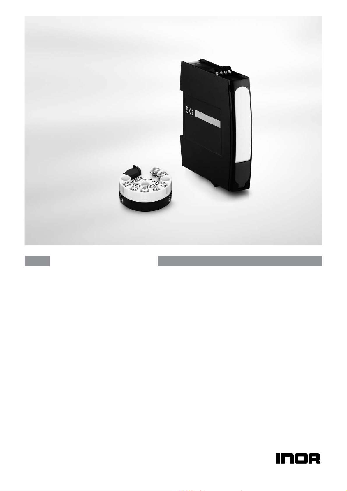
IPAQ C330/R330
IPAQ C330/R330
IPAQ C330/R330IPAQ C330/R330
Universal transmitter with NFC technology
The documentation is only complete when used in combination with the relevant
documentation for
adjustment and/or installation. All information is subject to change without notice.
the signal converter. The manual/handbook must be read prior to
© INOR 09/2020 - 4007317401 – MA IPAQ 330 R02 en
Page 2

:
IMPRINT
:::::::::::::::::::::::::::::::::::::::
2
www.inor.com
09/2020 - 4007317401 – MA IPAQ 330 R02 en
Page 3

IPAQ C330/R330
CONTENTS
1 Safety instructions 5
1.1 Intended use ..................................................................................................................... 5
1.2 Certifications .................................................................................................................... 6
1.2.1 EU directive compliance ......................................................................................................... 6
1.2.2 Ex approvals............................................................................................................................ 6
1.3 Safety instructions from the manufacturer ..................................................................... 7
1.3.1 Copyright and data protection ................................................................................................ 7
1.3.2 Disclaimer ............................................................................................................................... 7
1.3.3 Product liability and warranty ................................................................................................ 8
1.3.4 Information concerning the documentation........................................................................... 8
1.3.5 Warnings and symbols used................................................................................................... 9
1.4 Safety instructions for the operator................................................................................. 9
2 Device description 10
2.1 General description ........................................................................................................10
2.2 Nameplate ...................................................................................................................... 11
2.3 Scope of delivery............................................................................................................. 13
3 Installation 14
3.1 In-head transmitter........................................................................................................14
3.2 Rail mounting kit for in-head transmitters.................................................................... 15
3.3 Rail-mount transmitter .................................................................................................. 16
4 Electrical connections 17
4.1 Safety instructions.......................................................................................................... 17
4.2 Electrical connections of in-head transmitter............................................................... 19
4.3 Connection diagram of in-head transmitter.................................................................. 20
4.4 Connection diagram of in-head transmitter (intrinsically safe).................................... 20
4.5 Electrical connections of rail-mount transmitter.......................................................... 22
4.6 Connection diagram of rail-mount transmitter............................................................. 23
4.7 Connection diagram of rail-mount transmitter (intrinsically safe)............................... 23
5 Operation 24
5.1 NFC configuration and logging ...................................................................................... 24
5.2 Factory settings for configuration.................................................................................. 25
5.3 Configuration with ConSoft ............................................................................................ 26
5.4 Diagnostic information according to NAMUR NE 107 ................................................... 29
5.5 Factory default settings.................................................................................................. 31
5.6 Sensor error monitoring ................................................................................................ 31
5.7 System or sensor error correction ................................................................................ 31
6 Service 32
09/2020 - 4007317401 – MA IPAQ 330 R02 en
www.inor.com
3
Page 4

CONTENTS
IPAQ C330/R330
6.1 Accessory parts .............................................................................................................. 32
6.2 Spare parts availability...................................................................................................32
6.3 Availability of services .................................................................................................... 32
6.4 Returning the device to the manufacturer..................................................................... 32
6.4.1 General information.............................................................................................................. 32
6.4.2 Form (for copying) to accompany a returned device............................................................ 33
6.5 Disposal .......................................................................................................................... 33
6.5.1 Dispose of the transmitter.................................................................................................... 33
6.5.2 Disassembling and recycling................................................................................................ 34
6.5.3 Disassembling and recycling of IPAQ C330/C330X .............................................................. 34
6.5.4 Disassembling and recycling of IPAQ R330/R330X .............................................................. 35
6.5.5 Packaging of IPAQ C330/C330X and R330/R330X ................................................................ 37
7 Technical data 38
7.1 Measuring principles...................................................................................................... 38
7.1.1 Resistance temperature sensor ........................................................................................... 38
7.1.2 Thermocouples ..................................................................................................................... 39
7.2 Technical data................................................................................................................. 40
7.3 Dimensions ..................................................................................................................... 45
7.4 Temperature data for areas with potentially explosive atmospheres .......................... 46
7.5 Output load diagram....................................................................................................... 47
7.6 Electrical data for outputs and inputs............................................................................ 48
7.7 RTD and T/C accuracy table ........................................................................................... 49
8 Appendix 51
8.1 Installation and control drawings .................................................................................. 51
9 Notes 56
4
www.inor.com
09/2020 - 4007317401 – MA IPAQ 330 R02 en
Page 5
IPAQ C330/R330
1.1 Intended use
The IPAQ 330 signal conditioner is a universal two-wire transmitter intended to be used in
industrial environments and designed for:
• Temperature measurements with resistance thermometers
• Temperature measurements with thermocouples
• Voltage measurements in a range up to 1000 mV
• Resistance measurement up to 10 kΩ
• Measurements with potentiometers
C330 / C330X is intended for installation in a DIN B-head or larger
according to EN
R330 / R330X is intended for installation on a 35 mm DIN-rail
according to EN 60715/DIN 50022.
The transmitters are configured from a PC by using the ConSoft program and a transmitter
configuration kit (USB connection), or by a smartphone with built-in NFC support.
NFC applies only to later versions of, see table on page 10.
50446.
SAFETY INSTRUCTIONS
1
DANGER!
You may only use transmitters labelled with the "Ex" symbol in potentially explosive areas or
connect them to a sensor located in those areas. Additionally always note the zone(s) for which
the devices have an approval. Otherwise the transmitters might cause an explosion that can
result in fatal injuries.
DANGER!
Responsibility for the correct use of the devices with special regard to suitability, intended use
and the field of application lies solely with the operator. To avoid any kind of incorrect use, also
note the information in the chapter "Device description".
DANGER!
The transmitters do not contain any serviceable parts inside. Any substitution of components
may impair the intrinsic safety of the versions with an Ex approval. Always send defective devices
to the manufacturer or the local distributor for repair or exchange. If this is the case, attach a
clear description of the malfunction for warranty claims.
The manufacturer is not liable for any damage resulting from improper use or use for other than
the intended purpose. To avoid any kind of incorrect use, also note the information in the chapter
"Device description".
CAUTION!
Responsibility for the use of the measuring devices with regard to suitability, intended use and
corrosion resistance of the used materials against the measured fluid lies solely with the
operator.
This device is a Group 1, Class A device as specified within CISPR11. It is intended for use in
industrial environment. There may be potential difficulties in ensuring electromagnetic
compatibility in other environments, due to conducted as well as radiated disturbances.
09/2020 - 4007317401 – MA IPAQ 330 R02 en
www.inor.com
5
Page 6
1
SAFETY INSTRUCTIONS
1.2 Certifications
1.2.1 EU directive compliance
CE marking
The device fulfils all applicable statutory requirements of the following EU directives:
• EMC Directive 2014/30/EU, harmonized standards EN 61326-1 and EN 61326-2-3
• Devices for use in hazardous areas: ATEX Directive 2014/34/EU, harmonized standards
EN 60079-0 and EN 60079-11
• CE Directive 93/68/EC
• RoHS Directive 2011/65/EU, harmonized standard EN 50581.
• Radio Equipment Directive (RED) 2014/53/EU.
The manufacturer certifies successful testing of the product by applying the CE marking.
IPAQ C330/R330
1.2.2 Ex approvals
C330X (intrinsically safe), part no. 70C330X010 and 70C330X012
ATEX KIWA 16ATEX0038 X II 1 G Ex ia IIC T6...T4 Ga
IECEx IECEx KIWA 16.0016X Ex ia IIC T6...T4 Ga
USA FM17US0283X
Canada FM17CA0144X
R330X (intrinsically safe), part no. 70R330X010 and 70R330X012
ATEX KIWA 16ATEX0040 X II 1 G Ex ia IIC T6...T4 Ga
IECEx IECEx KIWA 16.0018X Ex ia IIC T6...T4 Ga
USA FM17US0283X
Canada FM17CA0144X
See also “Specific Conditions of Use" in the Ex certificates in the download area of the
manufacturer's website
IS CL I DIV 1 GP A-D, T6..
Cl I Zn 0 AEx/Ex ia IIC T6..T4 Ga
IS CL I DIV 1 GP A-D, T6..
Cl I Zn 0 AEx/Ex ia IIC T6...T4 Ga
.T4
.T4
6
www.inor.com
09/2020 - 4007317401 – MA IPAQ 330 R02 en
Page 7

IPAQ C330/R330
1.3 Safety instructions from the manufacturer
1.3.1 Copyright and data protection
The contents of this document have been created with great care. Nevertheless, we provide no
guarantee that the contents are correct, complete or up-to-date.
The contents and works in this document are subject to copyright. Contributions from third
parties are identified as such. Reproduction, processing, dissemination and any type of use
beyond what is permitted under copyright requires written authorisation from the respective
author and/or the manufacturer.
The manufacturer tries always to observe the copyrights of others, and to draw on works created
in-house or works in the public domain.
The collection of personal data (such as names, street addresses or e-mail addresses) in the
manufacturer's documents is always on a voluntary basis whenever possible. Whenever
feasible, it is always possible to make use of the offerings and services without providing any
personal data.
SAFETY INSTRUCTIONS
1
We draw your attention to the fact that data transmission over the Internet (e.g. when
communicating by e-mail) may involve gaps in security. It is not possible to protect such data
completely against access by third parties.
We hereby expressly prohibit the use of the contact data published as part of our duty to publish
an imprint for the purpose of sending us any advertising or informational materials that we have
not expressly requested.
1.3.2 Disclaimer
The manufacturer will not be liable for any damage of any kind by using its product, including,
but not limited to direct, indirect or incidental and consequential damages.
This disclaimer does not apply in case the manufacturer has acted on purpose or with gross
negligence. In the event any applicable law does not allow such limitations on implied warranties
or the exclusion of limitation of certain damages, you may, if such law applies to you, not be
subject to some or all of the above disclaimer, exclusions or limitations.
Any product purchased from the manufacturer is warranted in accordance with the relevant
product documentation and our Terms and Conditions of Sale.
The manufacturer reserves the right to alter the content of its documents, including this
disclaimer in any way, at any time, for any reason, without prior notification, and will not be liable
in any way for possible consequences of such changes.
www.inor.com09/2020 - 4007317401 – MA IPAQ 330 R02 en
7
Page 8

1
SAFETY INSTRUCTIONS
1.3.3 Product liability and warranty
The operator shall bear responsibility for the suitability of the device for the specific purpose.
The manufacturer accepts no liability for the consequences of misuse by the operator. Improper
installation or operation of the devices (systems) will cause the warranty to be void. The
respective "Standard Terms and Conditions" which form the basis for the sales contract shall
also apply.
1.3.4 Information concerning the documentation
To prevent any injury to the user or damage to the device it is essential that you read the
information in this document and observe applicable national standards, safety requirements
and accident prevention regulations.
If this document is not in your native language and if you have any problems understanding the
text, we advise you to contact your local office for assistance. The manufacturer can not accept
responsibility for any damage or injury caused by misunderstanding of the information in this
document.
This document is provided to help you establish operating conditions, which will permit safe and
efficient use of this device. Special considerations and precautions are also described in the
document, which appear in the form of icons as shown below.
IPAQ C330/R330
8
www.inor.com 09/2020 - 4007317401 – MA IPAQ 330 R02 en
Page 9
IPAQ C330/R330
1.3.5 Warnings and symbols used
Safety warnings are indicated by the following symbols.
DANGER!
This warning refers to the immediate danger when working with electricity.
DANGER!
This warning refers to the immediate danger of burns caused by heat or hot surfaces.
DANGER!
This warning refers to the immediate danger when using this device in a hazardous atmosphere.
DANGER!
These warnings must be observed without fail. Even partial disregard of this warning can lead to
serious health problems and even death.
SAFETY INSTRUCTIONS
1
WARNING!
Disregarding this safety warning, even if only in part, poses the risk of serious health problems.
There is also the risk of damaging the device or parts of the operator's plant.
CAUTION!
Disregarding these instructions can result in damage to the device or to parts of the operator's
plant.
These instructions contain important information for the handling of the device.
LEGAL NOTICE!
This note contains information on statutory directives and standards.
• HANDLING
HANDLING
HANDLINGHANDLING
This symbol designates all instructions for actions to be carried out by the operator in the
specified sequence.
i RESULT
RESULT
RESULTRESULT
This symbol refers to all important consequences of the previous actions.
1.4 Safety instructions for the operator
WARNING!
In general, devices from the manufacturer may only be installed, commissioned, operated and
maintained by properly trained and authorized personnel.
This document is provided to help you establish operating conditions, which will permit safe and
efficient use of this device.
www.inor.com09/2020 - 4007317401 – MA IPAQ 330 R02 en
9
Page 10

2
DEVICE DESCRIPTION
2.1 General description
The IPAQ 330 signal conditioner is a smart, digital 2-wire transmitter for temperature
measurements and other measurement applications in an industrial environment.
For further information about the possible measurements refer to
Configuration of the transmitter is possible with:
• PC configuration software ConSoft with PC configuration kit ICON-X.
• NFC interfac
of IPAQ 330, see table below . The smartphone app - INOR Connect, makes it possible to read,
write, save and share settings directly in the field.
The PC configuration software ConSoft is used for configuration, display and documentation.
The current ConSoft version is available for downloading on our website.
You can find configuration instructions in the ConSoft reference manual.
ConSoft is compatible with Windows XP/Vista/7/8/8.1/10.
e in a portable device such as a smartphone. NFC applies only to later versions
Intended use
IPAQ C330/R330
on page 5.
Different versions of the IPAQ 330
IPAQ Part Number NFC
C330 / C330X 70C3300010 / 70C330X010 No
70C3300012 / 70C330X012 Yes
R330 / R330X 70R3300010 / 70R330X010 No
70R3300012 / 70R330X012 Yes
IPAQ C330 - In-head transmitter
The IPAQ C
measurements
information about the possible measurements refer to
The in-head transmitter is optionally available in an intrinsically safe version for installation in
potentially explosive areas. These devices wear the "Ex" symbol and have an approval for
mounting into classified hazardous area, Zone 0, 1 and 2 / DIV 1 and 2.
All in-head versions are intended for installation in a DIN B-head or larger according to EN
50446 / DIN 43729. As an alternative you can also mount the in-head version on a 35 mm rail
according to EN 60715 / DIN 50022 with the help of the rail installation kit ( refer to
kit for in-head transmitters
330 is a smart, digital 2-wire universal in-head transmitter for temperature
and other me
asurement applications in an industrial environment. For further
Intended use
on page 5 .
Rail mounting
on page 15).
IPAQ R330 - Rail-mount transmitter
The IPAQ R330 rail-mount transmitter has the same features as the in-head version.
10
The rail-mount transmitter is optionally available in an intrinsically safe version for installation
into potentially explosive areas. All devices with an Ex approval wear the "Ex" symbol. The railmount transmitter is intended for installation on a 35 mm rail according to EN 60715 / DIN
50022.
www.inor.com
09/2020 - 4007317401 – MA IPAQ 330 R02 en
Page 11
IPAQ C330/R330
2.2 Nameplate
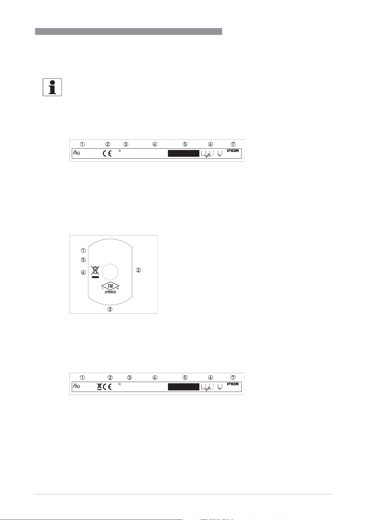
Look at the device nameplate to ensure that the device is delivered according to your order.
The transmitter can be identified by the information on the nameplates. For the different
versions of IPAQ 330 refer to
Nameplate for in-head transmitter - Part no. 70C330X010
C330X
www.inor.com
Figure 2-1: Example for round nameplate
1 Product name
2 CE marking (EC conformity)
3 Ex-relevant electrical data and Ex approvals
4 Part number, serial number (yyww = year and week of manufacturing) and batch number
5 Printable field, sensor configuration
6 Connections
7 Manufacturer and address
0539 II 1G Ex ia IIC T6...T4 Ga
KIWA 16ATEX0038 X
IECEx KIWA 16.0016X
DEVICE DESCRIPTION
NFC configuration and logging
12
70C330X010
Nyyww.xxxxxx
PO zzzzzzzzz
1 234
RTD
T/C
+
PO Box 9125
SE-200 39 Malmö
SWEDEN
2
on page 24.
Ui = Vmax: 30 V
Pi = Pmax: 0.9 W
Ii = Imax: 100 mA
Per Control Dwg
No. 4005488501
IS CL I DIV 1 GP ABCD T4...T6
FM17US0283X
FM17CA0144X
Cl I Zn 0 AEx/Ex ia IIC T4...T6 Ga
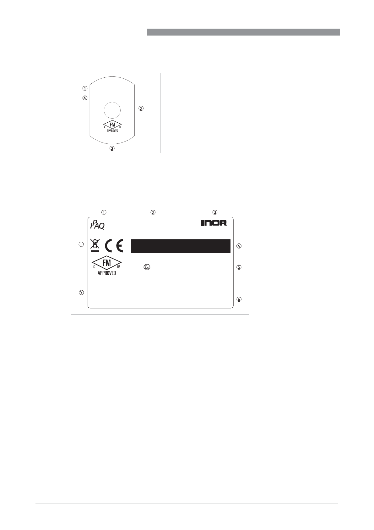
Figure 2-2: Example for bottom nameplate - Part no. 70C330X010
1 Electrical data for output
2 Ex-relevant electrical data
3 Ex approvals - North America
4 Electronic/electric device waste marking
5 Control drawing number
Nameplate for in-head transmitter - Part no. 70C330X012
12
C330X
www.inor.com
0539 II 1G Ex ia IIC T6...T4 Ga
KIWA 16ATEX0038 X
IECEx KIWA 16.0016X
70C330abcd
Nyyww.xxxxxx
PO zzzzzzzzz
Figure 2-3: Example for round nameplate
1 Product name
2 CE marking (EC conformity) and electric/electronic device waste marking
3 Ex-relevant electrical data and Ex approvals
4 Part number, serial number (yyww = year and week of manufacturing) and batch number
5 Printable field, sensor configuration
6 Connections
7 Manufacturer and address
1 234
RTD
T/C
+
PO Box 9125
SE-200 39 Malmö
SWEDEN
09/2020 - 4007317401 – MA IPAQ 330 R02 en
www.inor.com
11
Page 12
2
DEVICE DESCRIPTION
Ui = Vmax: 30 V
Pi = Pmax: 0.9 W
Ii = Imax: 100 mA
Per Control Dwg
No. 4005488502
FM17US0283X
FM17CA0144X
Ta: -40 to 55/70/85 °C for T6/T5/T4
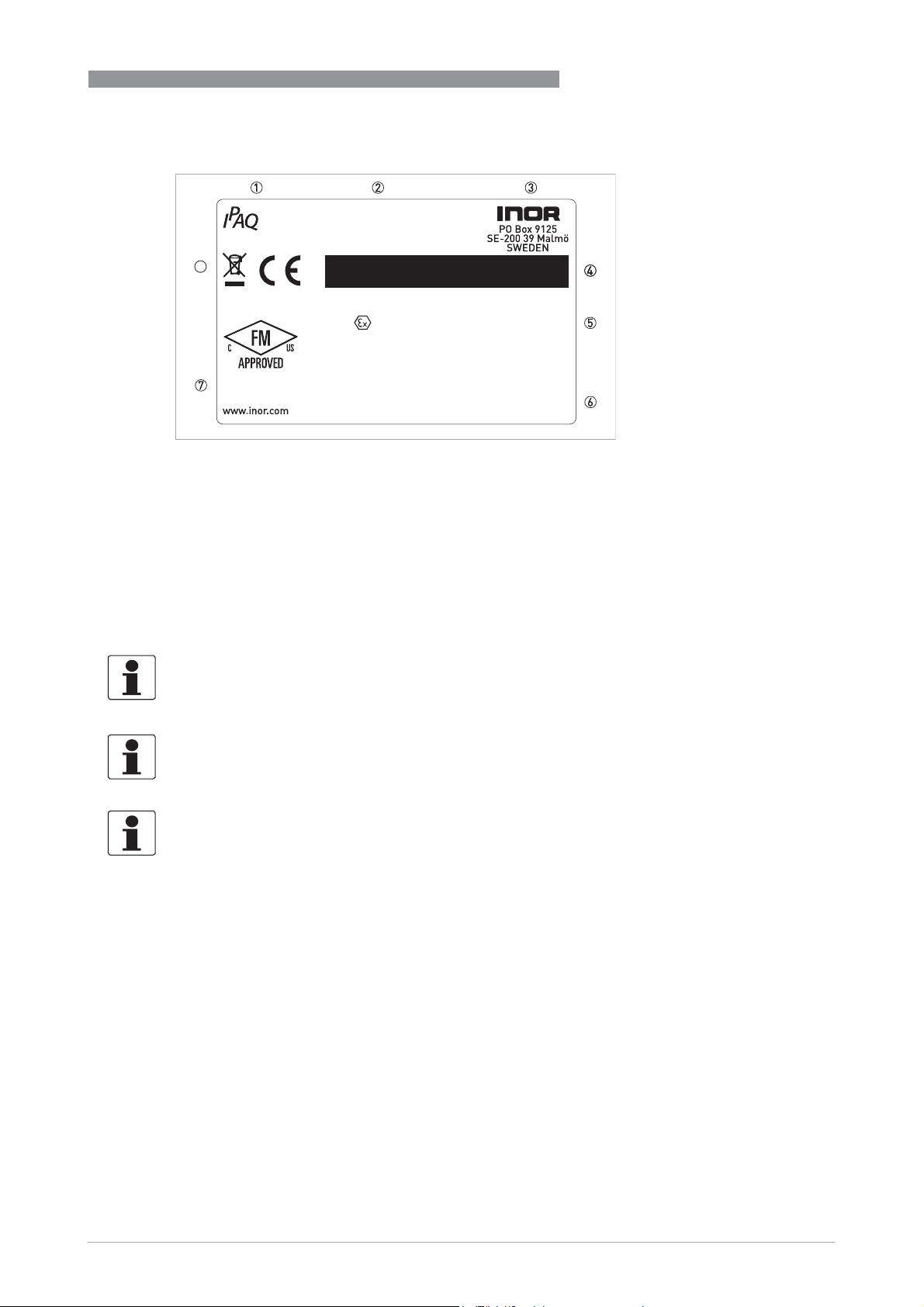
Figure 2-4: Example for bottom nameplate - Part no. 70C330X012
1 Electrical data for output
2 Ex-relevant electrical data
3 Ex approvals - North America
4 Control drawing number
Nameplate for rail-mount transmitter - Part no. 70R330X010
IS CL I DIV 1 GP ABCD T6...T4
Cl I Zn 0 AEx/Ex ia IIC T6...T4 Ga
IPAQ C330/R330
R330X
8
70R330X010
Nyyww.xxxxxx
PO ZZZZZZZZZ
PO Box 9125
SE-200 39 Malmö
SWEDEN
KIWA 16ATEX0040 X
IECEx KIWA 16.0018X
0539 II 1 G Ex ia IIC T6...T4 Ga
FM17US0283X
Max. ambient 85 °C
Per Control Dwg
No. 4005499601
www.inor.com
Figure 2-5: Example for nameplate
1 Product name
2 Part number, serial number (yyww = year and week of manufacturing) and batch number
3 Manufacturer and address
4 Printable field, sensor configuration
5 Ex-relevant electrical data and Ex approvals
6 Electrical data for output and input
7 Control drawing number
8 CE marking (EC conformity) and electronic/electric device waste marking
FM17CA0144X
IS CL I DIV 1 GP ABCD T4...T6
Cl I Zn 0 AEx/Ex ia IIC T4...T6 Ga
Ui: 30 V, Ii: 100 mA, Pi: 0.9 W, Ci: 23 nF, Li: 20 μH
Uo: 30 V, Io: 54 mA, Po: 405 mW, Co: 38.1 nF, Lo: 11 mH
12
www.inor.com
09/2020 - 4007317401 – MA IPAQ 330 R02 en
Page 13
IPAQ C330/R330
Nameplate for rail-mount transmitter- Part no. 70R330X012
DEVICE DESCRIPTION
2
R330X
8
Ta: -40 to 55/70/85 °C
for T6/T5/T4
Per Control Dwg
No. 4005499602
Figure 2-6: Example for nameplate
1 Product name
2 Part number, serial number (yyww = year and week of manufacturing) and batch number
3 Manufacturer and address
4 Printable field, sensor configuration
5 Ex-relevant electrical data and Ex approvals
6 Electrical data for output and input
7 Control drawing number
8 CE marking (EC conformity) and electronic/electric device waste marking
2.3 Scope of delivery
70R330abcd
Nyyww.xxxxxx
PO zzzzzzzzz
KIWA 16ATEX0040 X
IECEx KIWA 16.0018X
0539 II 1 G Ex ia IIC T6...T4 Ga
FM17US0283X
FM17CA0144X
IS CL I DIV 1 GP ABCD T6...T4
Cl I Zn 0 AEx/Ex ia IIC T6...T4 Ga
Ui: 30 V, Ii: 100 mA, Pi: 0.9 W, Ci: 23.1 nF, Li: 20 μH
Uo: 6.5 V, Io: 11.7 mA, Po: 19.1 mW, Co: 24 μF, Lo: 400 mH
Inspect the packaging carefully for damages or signs of rough handling. Report damage to the
carrier and to the local office of the manufacturer.
Do a check of the packing list to make sure that you have all the elements given in the order.
Look at the device nameplate to ensure that the device is delivered according to your order.
The scope of delivery always consists of the transmitter and its documentation.
09/2020 - 4007317401 – MA IPAQ 330 R02 en
www.inor.com
13
Page 14
3
INSTALLATION
3.1 In-head transmitter
DANGER!
IPAQ C330X must be installed in an enclosure having an Ingress Protection suitable for the
actual use but at least IP20.
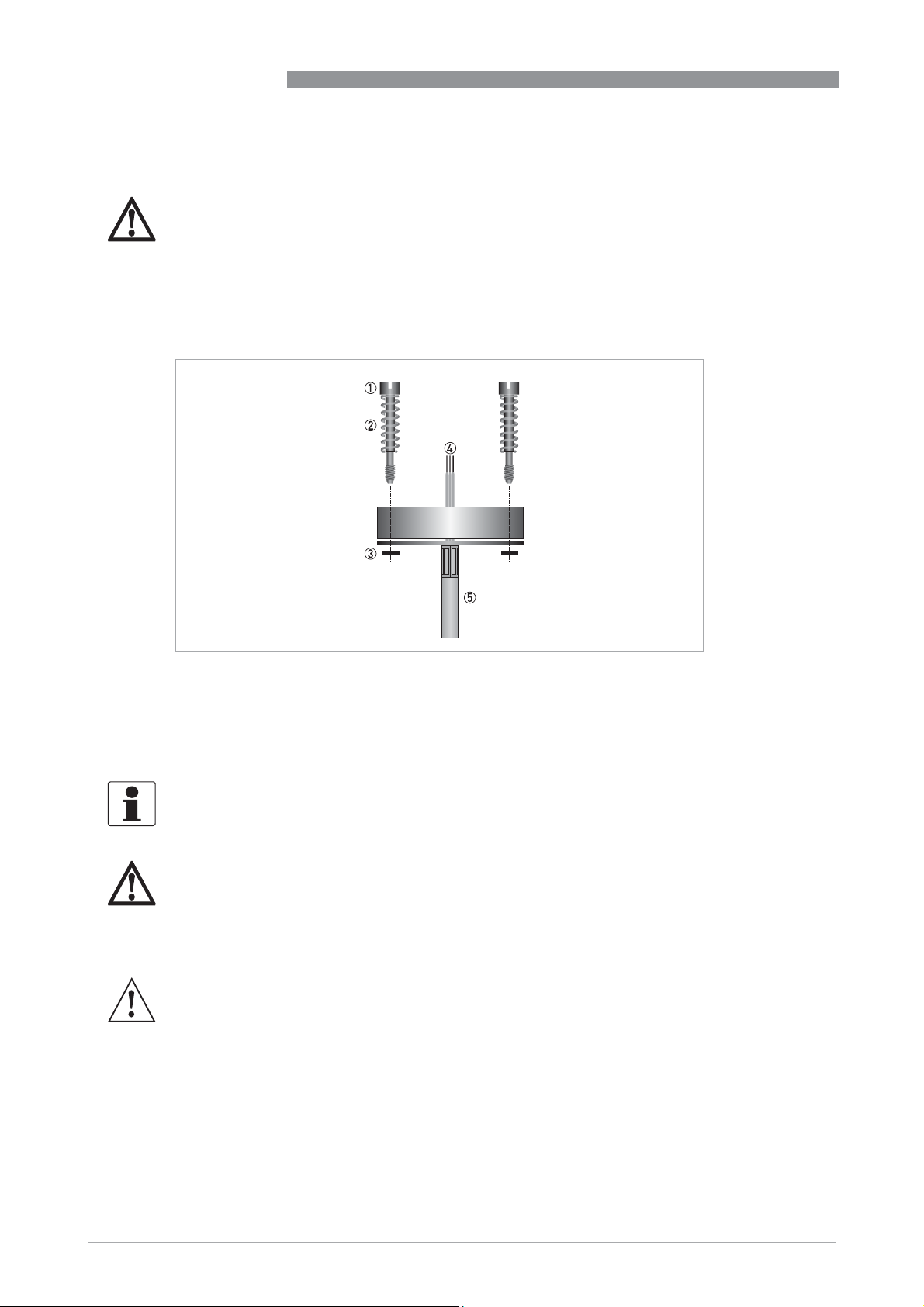
The transmitter is intended for installation in DIN B connection head or larger. For detailed
information refer to
Dimensions
IPAQ C330/R330
on page 45.
Figure 3-1: Connection head installation kit
1 M4 screw
2 Spring
3 Lock washer
4 Wires from the measuring insert.
5 MI cable
The connection head installation kit does not belong to the standard scope of delivery of the
transmitter, you have to order it separately.
DANGER!
The transmitter is optionally available in an intrinsically safe version (zone 0, 1 and 2 / DIV 1 and
2) for installation in potentially explosive atmospheres. The intrinsically safe version must be
supplied by an intrinsically safe power supply unit or Zener barrier placed outside of the
potentially explosive zone.
WARNING!
The transmitter has been developed for an operating temperature of -40...+85
°
C / -40...+185°F.
To avoid destruction or damage of the device, always assure that the operating temperature or
ambient temperature does not exceed the permissible range. The thermowell also transfer the
process temperature to the transmitter housing. If the process temperature is close to or
exceeds the maximum temperature of the transmitter, then the temperature in the transmitter
housing can rise above the maximum permissible temperature. One way to decrease the head
transfer via thermowell is to install the transmitter further away from the heat source. Inversely
similar measurements can be done if the temperature gets below specified minimum
temperature.
14
www.inor.com
09/2020 - 4007317401 – MA IPAQ 330 R02 en
Page 15
IPAQ C330/R330
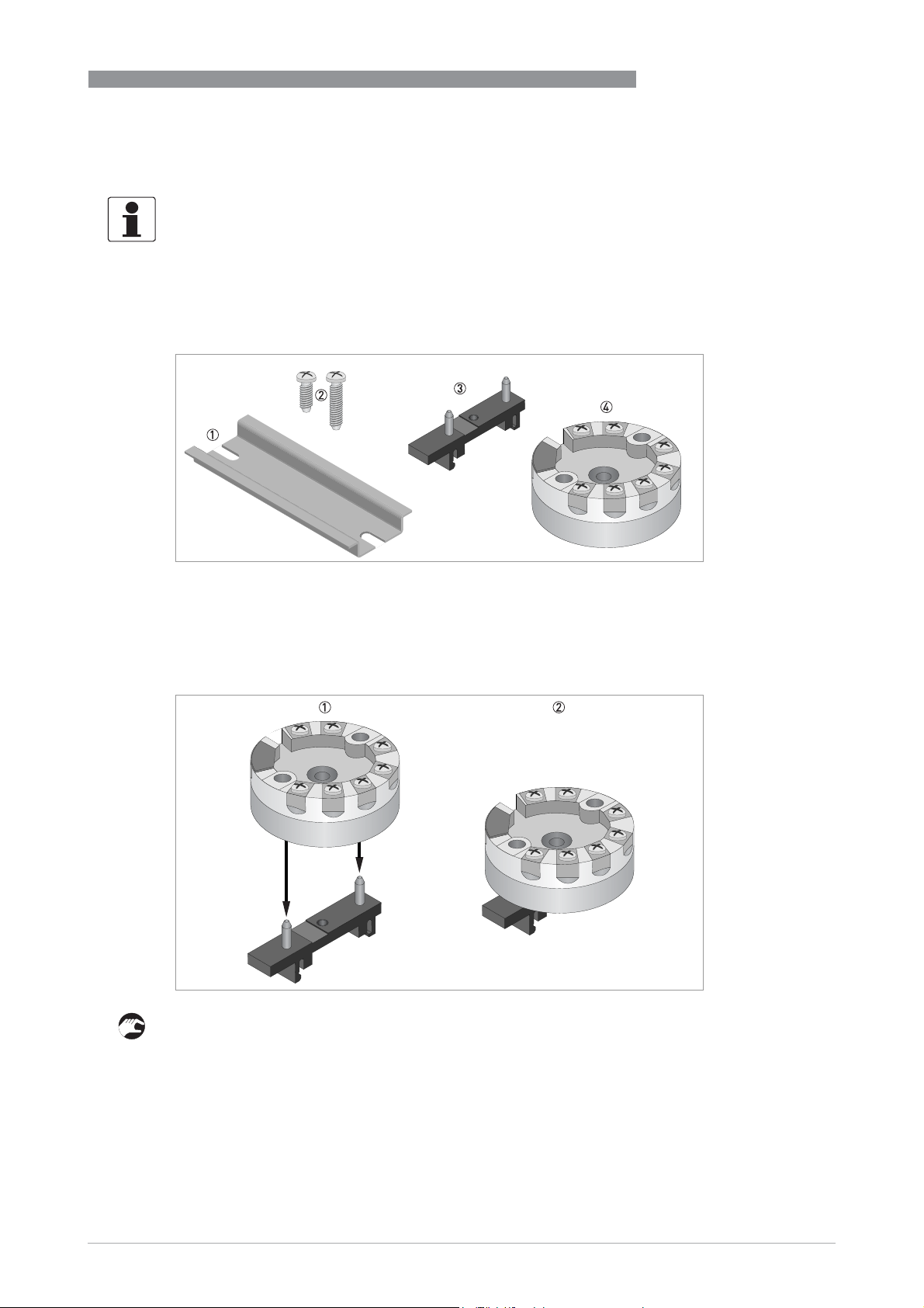
3.2 Rail mounting kit for in-head transmitters
The rail mounting kit allows to install the in-head transmitter on a rail according to EN 60715 /
DIN 50022.
The kit does not belong to the standard scope of delivery. You have to order it separately.
The screws in the kit is not to be used with this transmitter.
Rail mounting kit for in-head transmitters
INSTALLATION
3
Figure 3-2: Rail mounting kit for in-head transmitters
1 Rail (not included in the kit)
2 Screws (not needed)
3 Clip
4 Transmitter
Installation procedure: Step 1
1 Place the transmitter on the clip.
2 Press down the transmitter until it is attached to the clip.
www.inor.com09/2020 - 4007317401 – MA IPAQ 330 R02 en
15
Page 16
3
INSTALLATION
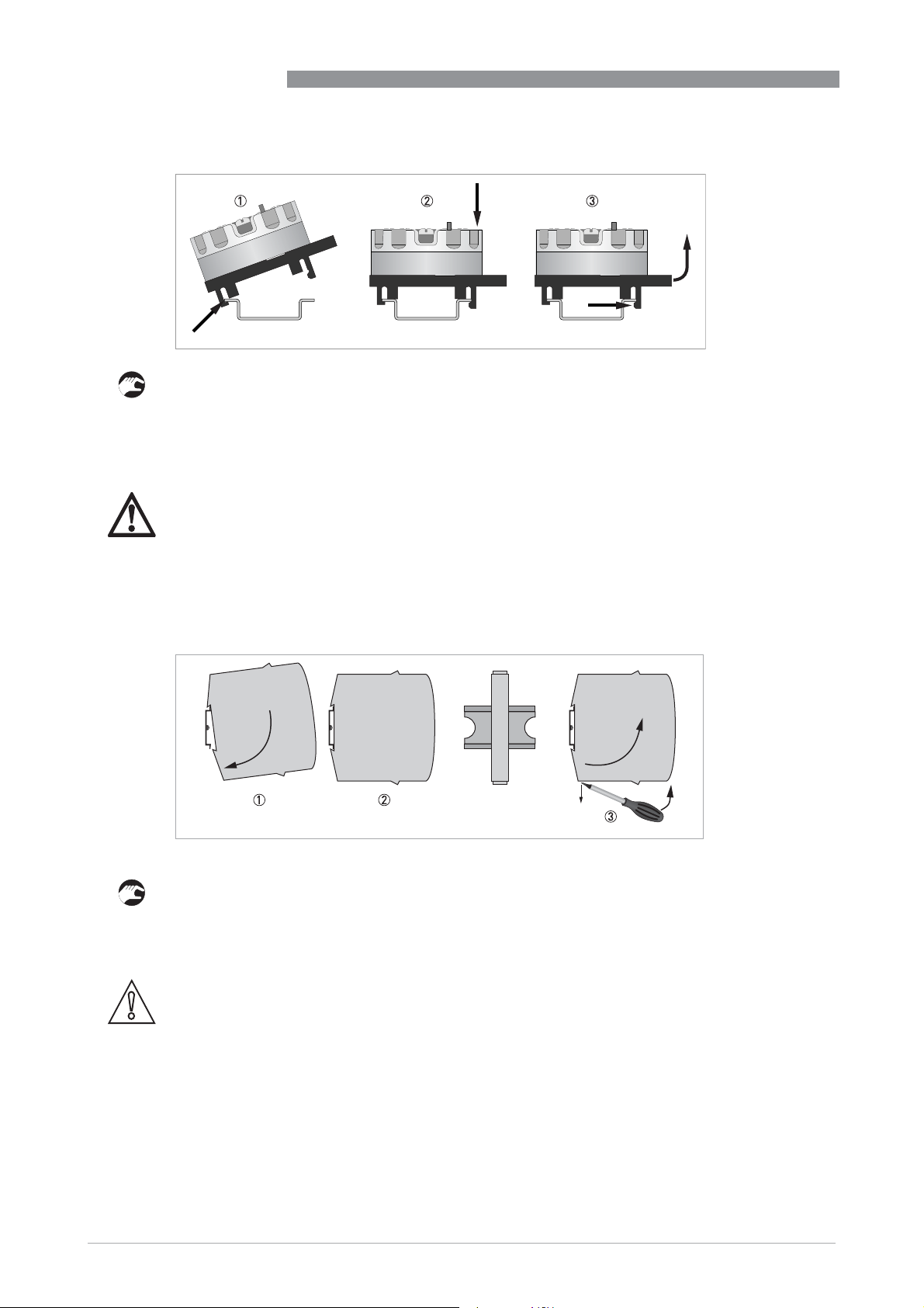
Installation procedure: Step 2
1 Hook one end of the clip into the rail.
2 Push the other end down until it snaps onto the rail.
3 Release by pushing the hook, and at the same time lift the clip out of the rail.
3.3 Rail-mount transmitter
DANGER!
IPAQ R330X must be installed in an enclosure having an ingress protection suitable for the
actual use but at least IP20.
IPAQ C330/R330
These transmitters are intended for installation on a 35 mm rail according to EN 60715 /
DIN 50022.
1 Fix the upper part of the transmitter onto the rail.
2 Press the lower part of the transmitter against the rail.
3 To remove the transmitter, bend the locking device using a small screwdriver. Carefully pull
the transmitter in the forward direction.
CAUTION!
The manufacturer has developed the R330 for an operating temperature range of
°
-40...+85
C / -40...+185°F.
To avoid destruction or damage of the device, always note the following items:
•
Assure that the operating temperature or the ambient temperature does not exceed the
permissible range.
16
www.inor.com
09/2020 - 4007317401 – MA IPAQ 330 R02 en
Page 17
IPAQ C330/R330
4.1 Safety instructions
DANGER!
All work on the electrical connections may only be carried out with the power disconnected.
Take note of the voltage data on the nameplate!
DANGER!
Observe the national regulations for electrical installations!
The transmitter is protected against polarity reversal. No damage will occur to the device if the
polarity of the supply voltage is switched. The output will then indicate 0 mA.
DANGER!
In potentially explosive areas, the intrinsically safe versions must be used.
The C330X / R330X (intrinsically safe) can be installed in potentially hazardous area zone 0, 1 and
2 / DIV 1 and 2.
The C330X / R330X (intrinsically safe) can be installed in potentially hazardous zone 0, 1 and 2 /
DIV 1 and 2 and the input may be connected to temperature sensors installed in zone 0 / DIV 1.
The intrinsically safe versions must be supplied by an intrinsically safe power supply unit or
Zener barrier placed outside of the potentially explosive area.
ELECTRICAL CONNECTIONS
4
DANGER!
Never connect or operate a non-Ex version of a transmitter in potentially explosive areas,
otherwise it might cause an explosion that can result in fatal injuries! Before you connect and
operate a transmitter version with an Ex approval, always note the following items to avoid an
explosion which may result in fatal injuries
•
Connect the Ex version only to Ex approved sensors or sensors that meet the requirements
for "simple apparatus" in EN 60079-11.
•
Observe the corresponding regulations, the declaration of conformity, the Ex type test
certificate of the device and the relevant instructions of this document.
•
The intrinsically safe versions must be supplied by an intrinsically safe power supply unit or a
Zener barrier placed outside of the potentially explosive area.
WARNING!
Observe without fail the local occupational health and safety regulations.
Any work done on the electrical components of the measuring device may only be carried out by
properly trained specialists.
Look at the device nameplate to ensure that the device is delivered according to your order.
Check for the correct supply voltage printed on the nameplate (applies only to the intrinsically
safe versions).
09/2020 - 4007317401 – MA IPAQ 330 R02 en
www.inor.com
17
Page 18

4
ELECTRICAL CONNECTIONS
DANGER!
For the transmitters used in hazardous areas following special conditions have to be considered:
The communication interface (USB connection) may only be connected to the associated ICON
interface if the temperature transmitter is outside of the hazardous area. If certified ICON-X
interface is used, a connected sensor may be located in the hazardous area. If non-Ex ICON
interface is used, a connected sensor shall not be located in the hazardous area.
For the permitted ambient temperature range, refer to Temperature data for areas with
potentially explosive atmospheres on page 46
The transmitter shall be mounted into a suitable enclosure that provides a degree of protection
of at least IP20.
The NFC Interface for communication must not be used in hazardous areas.
IPAQ C330/R330
18
www.inor.com
09/2020 - 4007317401 – MA IPAQ 330 R02 en
Page 19
IPAQ C330/R330
ELECTRICAL CONNECTIONS
4.2 Electrical connections of in-head transmitter
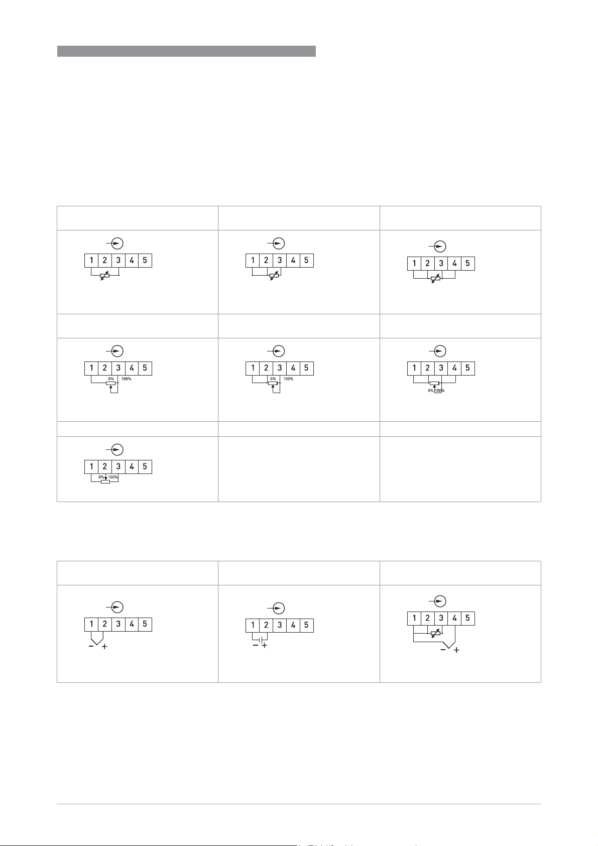
The input and output signals and the power supply must be connected in accordance with the
following illustrations. The transmitter is easy to install with the connection head installation kit.
To avoid measuring errors, all cables must be connected properly and the screws tightened
correctly.
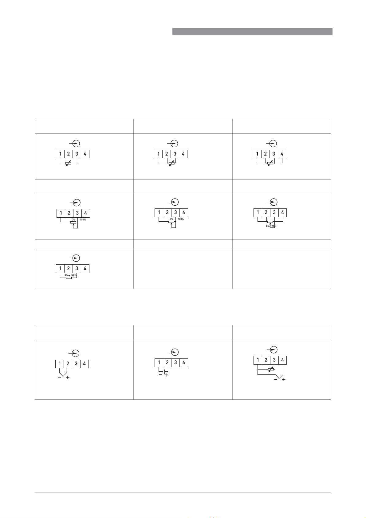
RTD and potentiometer measurement
RTD and potentiometer measurement
RTD and potentiometer measurementRTD and potentiometer measurement
Pt100
Pt100…Pt1000, Ni100, Ni120, Cu10
Pt100Pt100
2-wire connection
2-wire connection
2-wire connection2-wire connection
Resistance, 2-wire connection
Resistance, 2-wire connection Resistance, 3-wire connection
Resistance, 2-wire connectionResistance, 2-wire connection
Pt1000, Ni100, Ni120, Cu10
Pt1000, Ni100, Ni120, Cu10Pt1000, Ni100, Ni120, Cu10
Pt100
Pt100…Pt1000, Ni100, Ni120, Cu10
Pt100Pt100
3-wire connection
3-wire connection
3-wire connection3-wire connection
Resistance, 3-wire connection Resistance, 4-wire connection
Resistance, 3-wire connectionResistance, 3-wire connection
Pt1000, Ni100, Ni120, Cu10
Pt1000, Ni100, Ni120, Cu10Pt1000, Ni100, Ni120, Cu10
Pt100
Pt100…Pt1000, Ni100, Ni120, Cu10
Pt100Pt100
4-wire connection
4-wire connection
4-wire connection4-wire connection
Resistance, 4-wire connection
Resistance, 4-wire connectionResistance, 4-wire connection
Pt1000, Ni100, Ni120, Cu10
Pt1000, Ni100, Ni120, Cu10Pt1000, Ni100, Ni120, Cu10
4
Potentiometer, 3-wire slide wire
Potentiometer, 3-wire slide wire
Potentiometer, 3-wire slide wirePotentiometer, 3-wire slide wire
Thermocouple and voltage measurement
Thermocouple and voltage measurement
Thermocouple and voltage measurementThermocouple and voltage measurement
Thermocouple
Thermocouple Voltage
ThermocoupleThermocouple
Voltage Thermocouple with external CJC
VoltageVoltage
Thermocouple with external CJC
Thermocouple with external CJC Thermocouple with external CJC
(Pt100)
(Pt100)
(Pt100)(Pt100)
www.inor.com09/2020 - 4007317401 – MA IPAQ 330 R02 en
19
Page 20
4
ELECTRICAL CONNECTIONS
4.3 Connection diagram of in-head transmitter
CAUTION!
Always establish the electrical connections according to the following diagrams. Otherwise it
can come to destruction or damage of the transmitter. Note that the maximum output load
always depends on the power supply. If the maximum output load is exceeded, then the
measured value will become incorrect. For further information refer to Technical data on page
40
.
IPAQ C330/R330
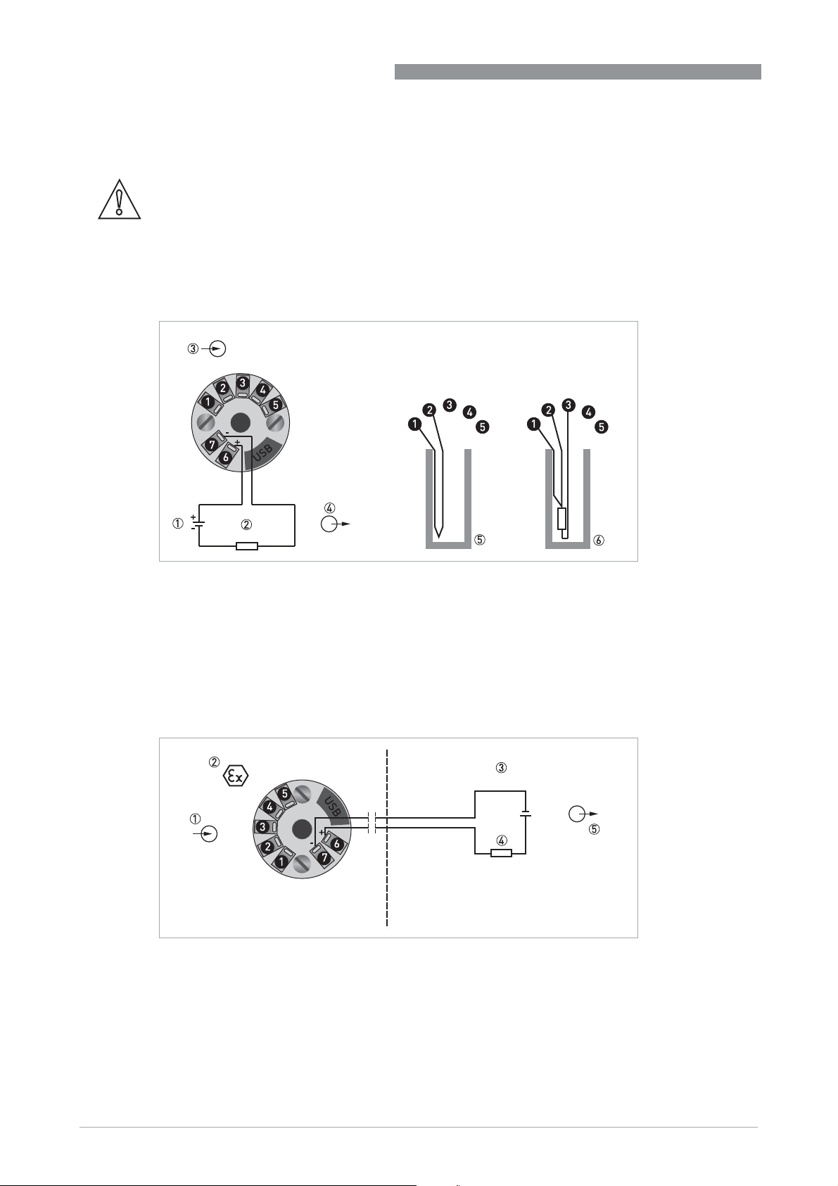
Figure 4-1: Connection diagram
1 Voltage supply VDC (terminals 6, 7)
2 R
Load
3 Input
4 Output
5 Pt100 3-wire connection
4.4 Connection diagram of in-head transmitter (intrinsically safe)
+
Figure 4-2: Connection diagram
1 Input (intrinsically safe)
2 Classified hazardous area (potentially explosive area e.g. zone 0, 1 and 2 / DIV 1 and 2)
3 Safe area
4 R
5 Zener barrier / Voltage supply 8.0…30 VDC (intrinsically safe) and output 4...20 mA
(intrinsically safe)
Load
20
www.inor.com
09/2020 - 4007317401 – MA IPAQ 330 R02 en
Page 21

IPAQ C330/R330
DANGER!
The transmitter may be operated in areas with potentially explosive atmospheres if the voltage
supply is ensured by means of an associated apparatus.
ELECTRICAL CONNECTIONS
4
www.inor.com09/2020 - 4007317401 – MA IPAQ 330 R02 en
21
Page 22
4
ELECTRICAL CONNECTIONS
4.5 Electrical connections of rail-mount transmitter
The input and output signals and the power supply must be connected in accordance with the
following illustrations. To avoid measuring errors, all cables must be connected properly and the
screws tightened correctly.
RTD and potentiometer measurement
RTD and potentiometer measurement
RTD and potentiometer measurementRTD and potentiometer measurement
Pt100
Pt100…Pt1000, Ni100, Ni120, Cu10
Pt100Pt100
2-wire connection
2-wire connection
2-wire connection2-wire connection
Resistance, 2-wire connection
Resistance, 2-wire connection Resistance, 3-wire connection
Resistance, 2-wire connectionResistance, 2-wire connection
Pt1000, Ni100, Ni120, Cu10
Pt1000, Ni100, Ni120, Cu10Pt1000, Ni100, Ni120, Cu10
Pt100
Pt100…Pt1000, Ni100, Ni120, Cu10
Pt100Pt100
3-wire connection
3-wire connection
3-wire connection3-wire connection
Resistance, 3-wire connection Resistance, 4-wire connection
Resistance, 3-wire connectionResistance, 3-wire connection
Pt1000, Ni100, Ni120, Cu10
Pt1000, Ni100, Ni120, Cu10Pt1000, Ni100, Ni120, Cu10
IPAQ C330/R330
Pt100
Pt100…Pt1000, Ni100, Ni120, Cu10
Pt100Pt100
4-wire connection
4-wire connection
4-wire connection4-wire connection
Resistance, 4-wire connection
Resistance, 4-wire connectionResistance, 4-wire connection
Pt1000, Ni100, Ni120, Cu10
Pt1000, Ni100, Ni120, Cu10Pt1000, Ni100, Ni120, Cu10
Potentiometer, 3-wire slide wire
Potentiometer, 3-wire slide wire
Potentiometer, 3-wire slide wirePotentiometer, 3-wire slide wire
Thermocouple and voltage measurement
Thermocouple and voltage measurement
Thermocouple and voltage measurementThermocouple and voltage measurement
Thermocouple
Thermocouple Voltage
ThermocoupleThermocouple
Voltage Thermocouple with external CJC
VoltageVoltage
Thermocouple with external CJC
Thermocouple with external CJC Thermocouple with external CJC
(Pt100)
(Pt100)
(Pt100)(Pt100)
22
www.inor.com
09/2020 - 4007317401 – MA IPAQ 330 R02 en
Page 23
IPAQ C330/R330
ELECTRICAL CONNECTIONS
4.6 Connection diagram of rail-mount transmitter
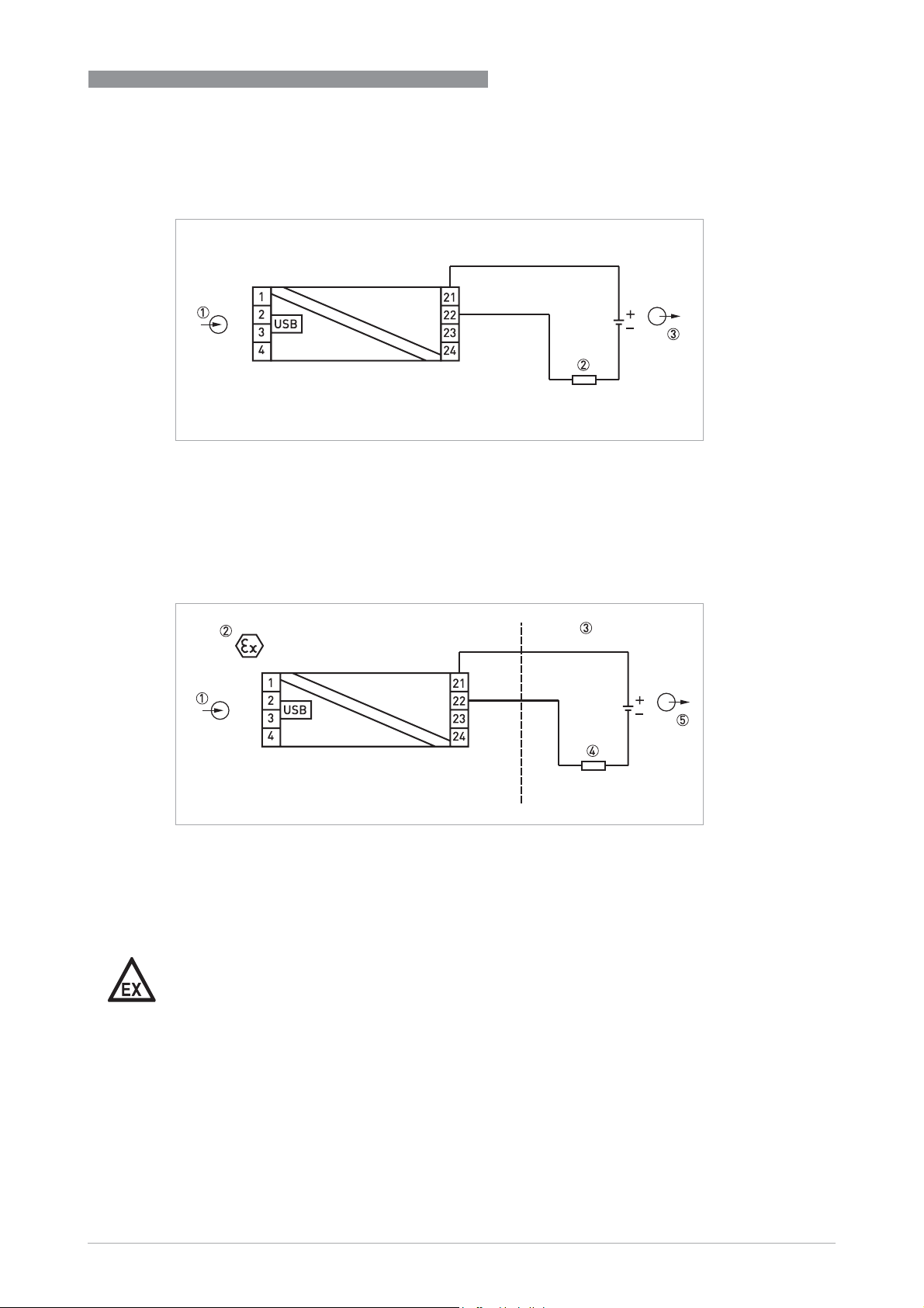
Figure 4-3: Connection diagram
1 Input
2 R
Load
3 Voltage supply 8...36 VDC and output 4...20 mA
4
4.7 Connection diagram of rail-mount transmitter (intrinsically safe)
Figure 4-4: Connection diagram
1 Input (intrinsically safe)
Classified hazardous area (potentially explosive area e.g. zone 0, 1 and 2 / DIV 1 and 2.
2
3 Safe area
4 R
5 Zener barrier / Voltage supply 8.0…30 VDC (intrinsically safe) and Output signal (4...20mA)
DANGER!
The transmitter may be operated in areas with potentially explosive atmospheres if the voltage
supply is ensured by means of an associated apparatus.
(intrinsically safe)
Load
www.inor.com09/2020 - 4007317401 – MA IPAQ 330 R02 en
23
Page 24

5
OPERATION
5.1 NFC configuration and logging
The IPAQ 330 contains an NFC interface (applies only to later versions of IPAQ 330, see table on
page 10) for communication with a smartphone app - INOR Connect. The configuration
procedure uses the NFC function in combination with a smartphone with built-in NFC support to
perform all settings of the transmitter. The transmitter does not need any power or other
external connection, just to be close to the smartphone. The app makes it possible to read, write,
save and share settings directly in the field.
The logging function give the possibility to log events directly in the field without any other
equipment beside the smartphone. The logged data can be stored or shared by the mobile
network. It makes it also very simple to read and display the actual measuring value in the
transmitter.
The app does also give direct access to the transmitter documentation and calibration data
through an internet connection.
NFC applies only to IPAQ 330 according to the table on page 10.
IPAQ C330/R330
24
www.inor.com
09/2020 - 4007317401 – MA IPAQ 330 R02 en
Page 25

IPAQ C330/R330
5.2 Factory settings for configuration
The transmitters are delivered with either a factory settings or configured according to
customers' specifications.
Parameter Factory settings
Type of sensor RTD Pt100 α = 0.003850
Number of wires 3
PV Lower range value 0
PV Upper range value 100
Temperature units °C
Damping value 1.4s
Sensor break
(Downscale/Upscale)
Sensor short circuit
(Downscale/Upscale)
Upscale
Upscale
OPERATION
5
www.inor.com09/2020 - 4007317401 – MA IPAQ 330 R02 en
25
Page 26
5
OPERATION
5.3 Configuration with ConSoft
The ConSoft is a PC based graphical user interface for configuration of the transmitters. The PC
configuration software ConSoft is used for configuration, display and documentation. The
current software versions of ConSoft and the USB interface are available for downloading on our
website.
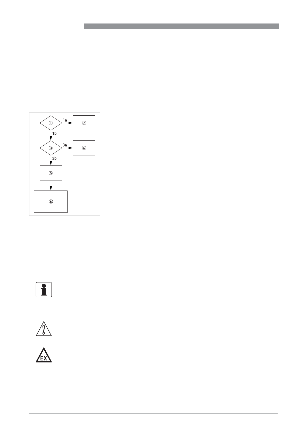
To upgrade your USB interface software to the latest version, use the following flow chart.
1 Is the USB interface version 1.2.00 or higher?
1a No
1b Yes
2 No possibility of updating for hardware version below 1.2.00. Replace the USB
interface with newer version.
3 Is a ConSoft version 1.2.0.0 or higher installed on your PC?
3a No
3b Yes
4 Download the current ConSoft version from our website and install it on your
PC.
5 Download the current software file [USB_x.y.zz.hex] for the USB interface from
our website to your PC either on your desktop or in a folder made for this
purpose.
6 1. Start ConSoft
2. Connect the USB interface to the PC. Note that no other device should be
connected during updating of the USB interface.
3. Click on Options/Update USB Interface/Load file (type the path for the
software file downloaded on your desktop or in a separate folder).
4. Wait until "File OK" message is on the screen.
5. Click on "Start update". A message "Programming!" and a green status
indicator show up on the screen. The update will take about one minute.
6. Wait until "Ready USB Interface" message is displayed on the screen. Close
the update window. The USB interface is now ready for use.
IPAQ C330/R330
26
Full functionality of the transmitter is achieved with ConSoft program version 3.2.0 or later and
the firmware in the USB Interface must have a version number 1.2.07 or later. Consoft is
compatible with Windows XP/Vista/7/8/8.1/10. The current software version of ConSoft and the
USB interface are available for downloading on our website.
CAUTION!
Only use the manufacturer's configuration kit for PC configuration. Another configuration kit
could destroy or damage the transmitter.
DANGER!
The transmitter's communication port (USB connection) may only be connected to the certified
ICON-X Interface. When the ICON-X is connected, the temperature transmitter shall be ouside of
the hazardous area; a connected sensor may be located in the hazardous area.
For the applicable ambient temperature range , see the control drawings for C330X/R330X at the
end of this book, and for ICON-X - 4006801801
www.inor.com
.
09/2020 - 4007317401 – MA IPAQ 330 R02 en
Page 27
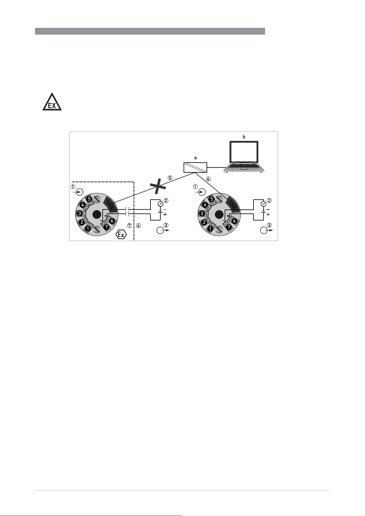
IPAQ C330/R330
Proper connection of the transmitters with a PC requires our USB interface which is included in
the ICON-X configuration kit. For connection of the transmitters refer to the following connection
diagrams during configuration.
DANGER!
Make sure the area is safe before connecting the USB interface ICON-X to the transmitter.
OPERATION
5
Figure 5-1: Connection during configuration of in-head transmitter
a = PC configuration kit; b = PC software ConSoft
1 Input (intrinsically safe)
2 R
3 Output voltage supply (intrinsically safe terminals 6 and 7)
4 Communication with USB interface and a PC software ConSoft
5 Connection to USB interface and a PC software ConSoft is not permitted if Ex version of IPAQ C330 (IPAQ C330X) is
6 Safe area
7 Classified hazardous area (potentially explosive area e.g. zone 0, 1 and 2 / DIV 1 and 2)
(intrinsically safe)
Load
placed in the classified hazardous area (potentially explosive area)
www.inor.com09/2020 - 4007317401 – MA IPAQ 330 R02 en
27
Page 28
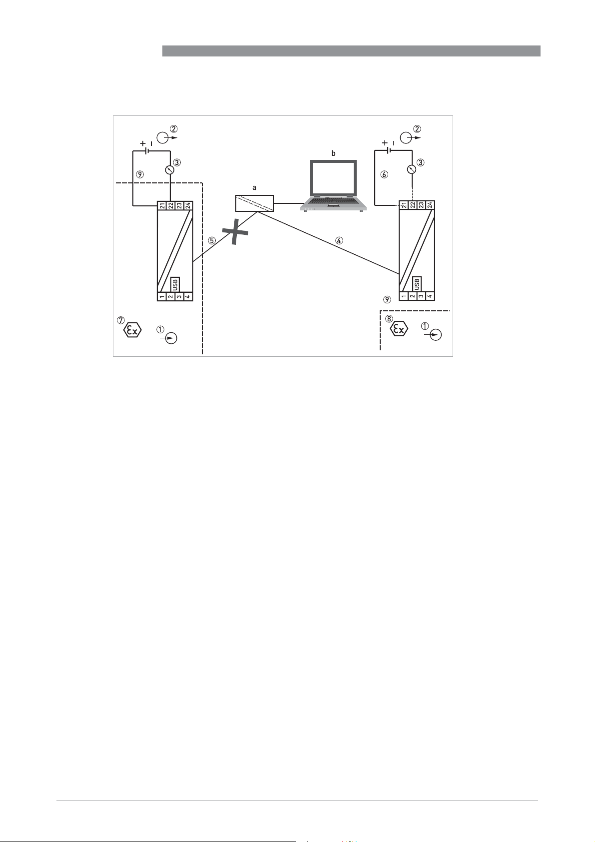
5
OPERATION
IPAQ C330/R330
Figure 5-2: Connection during configuration of rail-mount transmitter
a = PC configuration kit; b = PC software ConSoft
1 Input (intrinsically safe)
2 Voltage supply (intrinsically safe terminals 21, 22)
3 R
4 Communication with USB interface and a PC software ConSoft
5 Connection to USB interface and a PC software ConSoft is not permitted if Ex version of IPAQ R330 (IPAQ R330X) is
6 Connection to the voltage supply during configuration with USB interface and PC software ConSoft is not needed
7 Classified hazardous area (potentially explosive area e.g. zone 0 / DIV 1)
8 Classified hazardous area (potentially explosive area e.g. zone 0, 1 and 2 / DIV 1 and 2)
9 Safe area
(intrinsically safe)
Load
placed in the classified hazardous area (potentially explosive area)
28
www.inor.com
09/2020 - 4007317401 – MA IPAQ 330 R02 en
Page 29

IPAQ C330/R330
OPERATION
5.4 Diagnostic information according to NAMUR NE 107
Diagnostic information about the connected sensor is available in the configuration software
ConSoft or via NFC when using a portable device.
In accordance with NAMUR NE 107 for:
• Sensor break (failure / sensor wire break)
• Sensor short-circuit (failure / sensor wire short-circuit)
• Transmitter error (failure/transmitter error, non-correctable in the transmitter)
For complete information about all diagnostic information available from the transmitters,
connection to the chosen sensor and current loop should be established.
Messages in ConSoft Actions
Device specific Error message Error correction
Device Specific Status
Device Specific Status additional device status information, which are described below.
Device Specific StatusDevice Specific Status
Transmitter Underrange Measurement is under specified range. Check the specified lower
Transmitter Overrange Measurement is over specified range. Check the specified high range
Transmitter Ad_short See Sensor short circuit (same error cause).
Transmitter Ad_open See Sensor break (same error cause).
Transmitter Sensor break Sensor wire broken. Check the sensor and sensor connection. If
Transmitter Sensor short circuit Sensor wire shorted. Check the sensor and sensor. If error remains
Transmitter Sensor invalid Invalid sensor selected. Check the sensor selection. If error remains
Transmitter Linearization table invalid Linearization table invalid. Check Linearization table settings. If error
Transmitter Loop voltage too low N/A
Transmitter Dac out of range Digital-to-Analog-Converter out of max range. Power cycle the
Transmitter Dac feedback error (+/-
10%)
Transmitter Loop resistance out of
range
Transmitter Dac acknowledge error No acknowledge from Digital-to-Analog-Converter. Power cycle the
Transmitter System non-recoverable
errors
Transmitter Process Maintenance required: Process
Transmitter Configuration Maintenance required: Configuration
Transmitter Electronics Maintenance required: Electronics
Transmitter Sensor Maintenance required: Sensor
Transmitter Process Out of Specification: Process
Transmitter Configuration Out of Specification: Configuration
range and sensor and sensor connection. If error remains replace
the sensor.
and sensor and sensor connection. If error remains replace the
sensor.
error remains replace the sensor.
replace the sensor.
replace device.
remains replace device.
device. If error remains replace device.
N/A
Loop Resistance out of range (RLoad [Ω] = (U-8.0)/0.022)). Check loop
connection and voltage. If error remains replace device.
device. If error remains replace device.
Internal system non-recoverable error. Power cycle the device. If
error remains replace device.
5
www.inor.com09/2020 - 4007317401 – MA IPAQ 330 R02 en
29
Page 30

5
OPERATION
IPAQ C330/R330
Messages in ConSoft Actions
Device specific Error message Error correction
Transmitter Electronics Out of Specification: Electronics
Transmitter Sensor Out of Specification: Sensor
Transmitter Process Check: Process
Transmitter Configuration Check: Configuration
Transmitter Electronics Check: Electronics
Transmitter Sensor Check: Sensor
Transmitter Process Failure: Process
Transmitter Configuration Failure: Configuration
Transmitter Electronics Failure: Electronics
Transmitter Sensor Failure: Sensor
Transmitter High Alarm Check the sensor and sensor connection. If error remains replace the
Transmitter Low Alarm Check the sensor and sensor connection. If error remains replace the
sensor.
sensor.
30
www.inor.com
09/2020 - 4007317401 – MA IPAQ 330 R02 en
Page 31

IPAQ C330/R330
5.5 Factory default settings
The transmitters are delivered with a factory configuration Pt100 (α = 0.00385), 3-wire
connection 0...+100°C / +32...+212°F, sensor error monitoring "Upscale", filtering level 1.4 s or
configured according to customer’s requirements.
Due to the long-term drift of max. ±0.02% of span per year, a re-calibration of the transmitter is
normally not needed. Should you for any reason require the re-calibration, the transmitter must
be returned to the factory.
5.6 Sensor error monitoring
In case of a sensor break or short circuit the transmitter indicates this by either drop the output
<3.6 mA or lift it to >21.0 mA. The sensor error indication is individually configurable and is set
via the configuration software.
5.7 System or sensor error correction
System error correction
To perform a system error correction a dry block cell or a temperature bath together with a
calibrated reference thermometer is needed. The system is the sensor + transmitter. Expose the
sensor to one (one-point correction) or two (two-point correction) accurately measured
temperatures (true temperatures), while the transmitter is connected to the configuration
software. The true temperature(s) are entered into the software, and the transmitter
automatically corrects for the system errors.
OPERATION
5
Sensor error correction
If the temperature sensor is calibrated, or the sensor error compared to the standard curve is
known, then the sensor error (deviation from the standard curve) can be entered into the
transmitter via the configuration software and the transmitter corrects for the sensor errors.
www.inor.com09/2020 - 4007317401 – MA IPAQ 330 R02 en
31
Page 32
6
SERVICE
6.1 Accessory parts
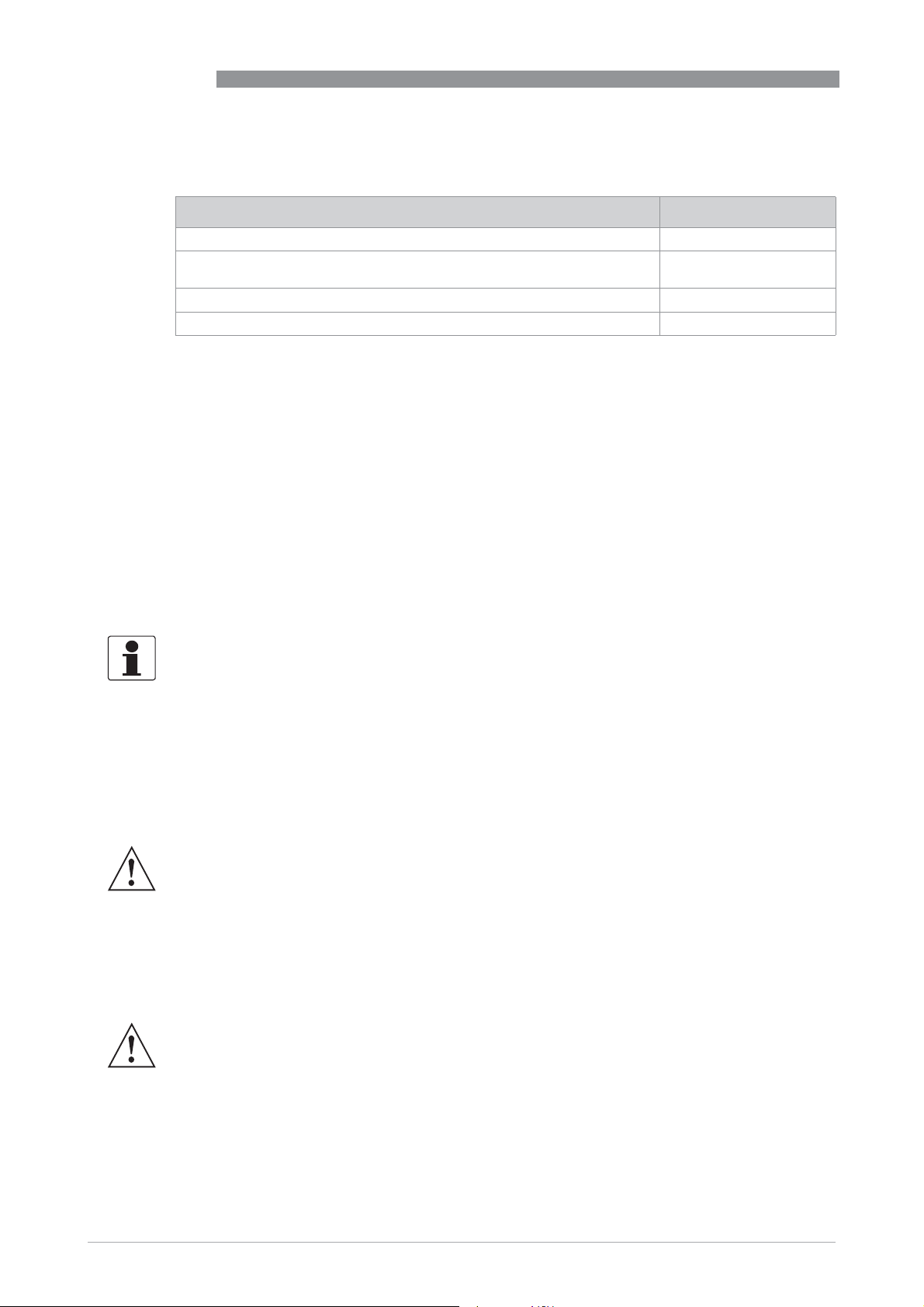
Accessory part Order code
Universal rail mounting kit for in-head version 70ADA00015
Ex configuration kit including Ex approved modem, software ConSoft and
cables for USB connection.
Connection Head installation kit 70ADA00017
ICON-BT, Bluetooth configuration kit 70CFGBT001
6.2 Spare parts availability
The manufacturer adheres to the basic principle that functionally adequate spare parts for each
device or each important accessory part will be kept available for a period of 3 years after
delivery of the last production run for the device.
This regulation only applies to spare parts which are subject to wear and tear under normal
operating conditions.
IPAQ C330/R330
70CFGUSX01
6.3 Availability of services
The manufacturer offers a range of services to support the customer after expiration of the
warranty. These include repair, maintenance, technical support and training.
For more precise information, please contact your local sales office.
6.4 Returning the device to the manufacturer
6.4.1 General information
This device has been carefully manufactured and tested. If installed and operated in accordance
with these operating instructions, it will rarely present any problems.
WARNING!
Should you nevertheless need to return a device for inspection or repair, please pay strict
attention to the following points:
•
Due to statutory regulations on environmental protection and safeguarding the health and
safety of the personnel, the manufacturer may only handle, test and repair returned devices
that have been in contact with products without risk to personnel and environment.
•
This means that the manufacturer can only service this device if it is accompanied by the
following certificate (see next section) confirming that the device is safe to handle.
32
WARNING!
If the device has been operated with toxic, caustic, radioactive, flammable or water-endangering
products, you are kindly requested:
•
to check and ensure, if necessary by rinsing or neutralising, that all cavities are free from
such dangerous substances,
•
to enclose a certificate with the device confirming that it is safe to handle and stating the
product used.
www.inor.com
09/2020 - 4007317401 – MA IPAQ 330 R02 en
Page 33
IPAQ C330/R330
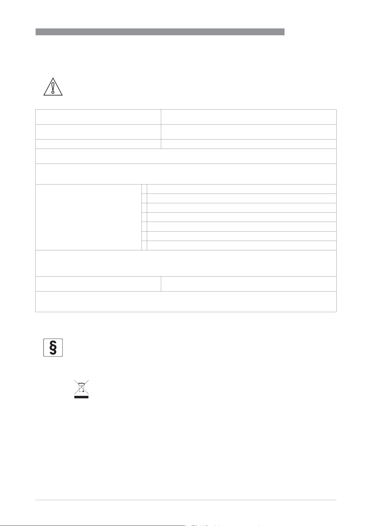
6.4.2 Form (for copying) to accompany a returned device
CAUTION!
To avoid any risk for our service personnel, this form has to be accessible from outside of the
packaging with the returned device.
Company: Address:
Department: Name:
Telephone number: Email address:
Manufacturer order number or serial number:
The device has been operated with the following medium:
This medium is: radioactive
water-hazardous
toxic
caustic
flammable
We checked that all cavities in the device are free from such substances.
We have flushed out and neutralized all cavities in the device.
SERVICE
6
We hereby confirm that there is no risk to persons or the environment caused by any residual media contained in this
device when it is returned.
Date: Signature:
Stamp:
6.5 Disposal
LEGAL NOTICE!
Disposal must be carried out in accordance with legislation applicable in your country.
Separate collection of WEEE (Waste Electrical and Electronic Equipment) in the European Union:
Separate collection of WEEE (Waste Electrical and Electronic Equipment) in the European Union:
Separate collection of WEEE (Waste Electrical and Electronic Equipment) in the European Union:Separate collection of WEEE (Waste Electrical and Electronic Equipment) in the European Union:
According to the directive 2012/19/EU, the monitoring and control instruments marked with the
WEEE symbol and reaching their end-of-life must not be disposed of with other waste
The user must dispose of the WEEE to a designated collection point for the recycling of WEEE or
send them back to our local organisation or authorised representative.
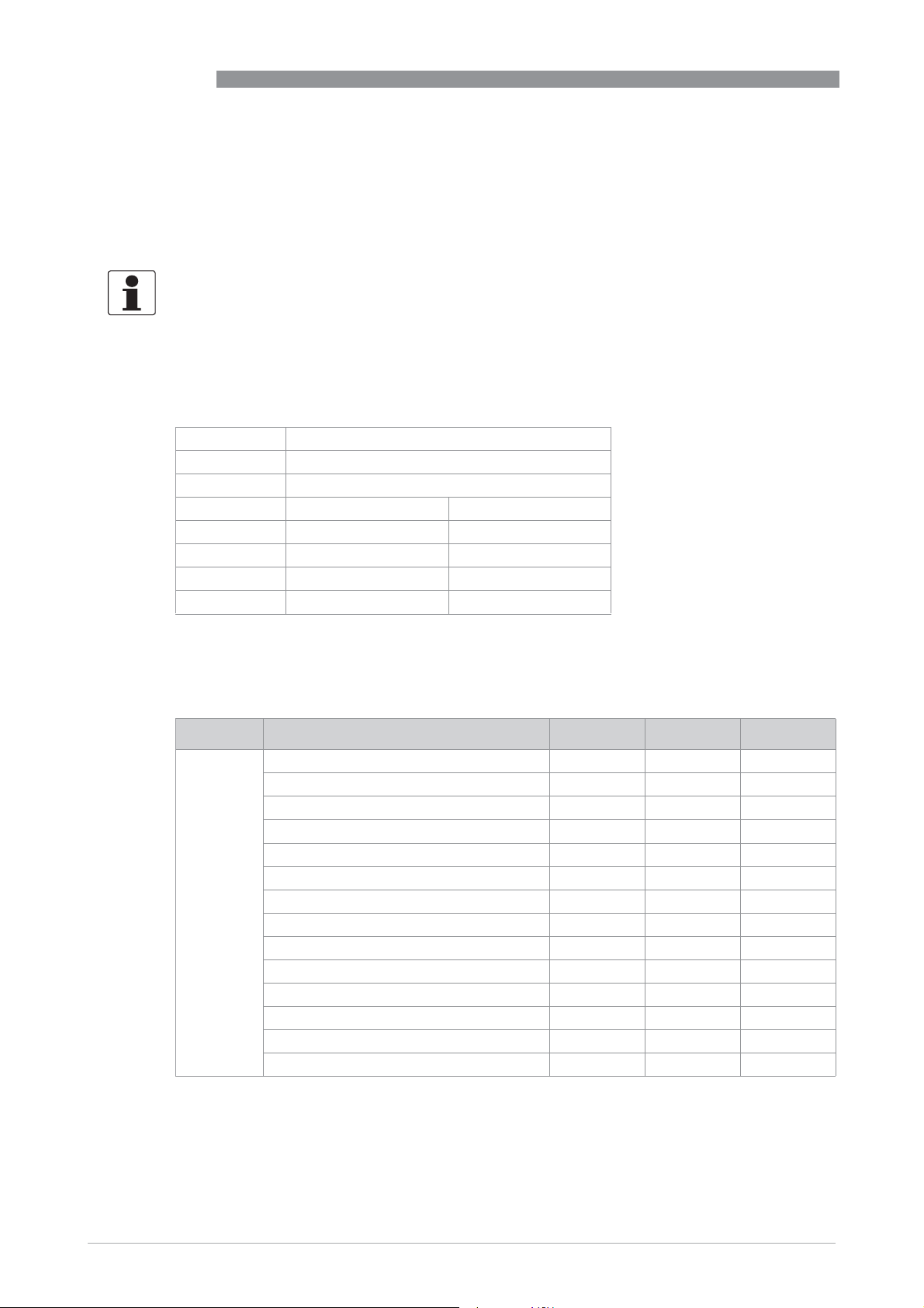
6.5.1 Dispose of the transmitter
Dispose of the transmitter, sensor and packaging materials in an environmentally compatible
way and in accordance with the country-specific waste disposal regulations.
must not be disposed of with other waste.
must not be disposed of with other wastemust not be disposed of with other waste
www.inor.com09/2020 - 4007317401 – MA IPAQ 330 R02 en
33
Page 34
6
SERVICE
6.5.2 Disassembling and recycling
This section describes (in short) the instructions of handling and disassembling the device when
it’s reached EOL (end of life) or is disposed after usage. The information given is sufficient to
gather the most important parts of the device (by the end-user) which can be used for recycling.
The products do not contain dangerous gases or materials. If there is contamination from the
process, refer to Returning the device to the manufacturer on page 32
6.5.3 Disassembling and recycling of IPAQ C330/C330X
Type IPAQ
Model C330 / C330X
Usage Signal conditioner for resistance and voltage
Weight [g] Weight [lb]
Total 35.2 0.08
Metal parts 10.8 0.02
Ceramic fibers 0.3 0.00
Plastic parts 24.1 0.05
IPAQ C330/R330
.
To achieve reliability and quality performance of the product IPAQ C330/C330X is encapsulated in
casting polymer plastic resulting in that dismantling of the IPAQ C330/C330X is not possible. The
content of the IPAQ C330/C330X can be found in the following table.
Material CAS Weight [g] Weight [%]
Thermoplastic NA 19.3 54.8
Stainless steel NA 5.2 14.8
Brass NA 3.5 9.9
Zinc 7440-66-6 0.3 0.9
Silicone 7440-21-3 0.8 2.3
Epoxy NA 3.6 10.2
Lead free solder NA 0.3 0.9
Nitrile NA 0.2 0.6
Copper 7440-50-8 0.9 2.6
Polyester NA 0.2 0.6
Nickel 7723-14-0 0.5 1.4
Alumina (Al2O3) 1344-28-1 0.2 0.6
Gold (Au) 7444-57-6 0.1 0.3
Barium titanat (BaTiO3) 12047-27-7 0.1 0.3
34
www.inor.com
09/2020 - 4007317401 – MA IPAQ 330 R02 en
Page 35

IPAQ C330/R330
Material CAS Weight [g] Weight [%]
RoHS Polybrominated diphenyl Ethers (PBDE) NA 0 0
Cadmium (Cd) 7440-43-9 0 0
Mercury (Hg) 7439-97-6 0 0
Lead (Pb) 7440-31-7 0 0
Chrome VI (Cr VI) 7440-47-3 0 0
Polybrominated biphenyls (PBB) NA 0 0
Bis (2-ethylhexil) phthalate (DEHP) 117-81-7 0 0
Butyl benzyl phthalate (BBP) 85-68-7 0 0
Dibutyl phthalate (DBP) 84-74-2 0 0
Diisobutyl phthalate (DIBP) 84-69-5 0 0
6.5.4 Disassembling and recycling of IPAQ R330/R330X
Type IPAQ
Model R330 / R330X
Usage Signal conditioner for resistance and voltage
Weight [g] Weight [lb]
Total 63.8 0.14
Metal parts 9.4 0.02
Ceramic fibres 0.2 0.00
Plastic parts 54.2 0.12
SERVICE
6
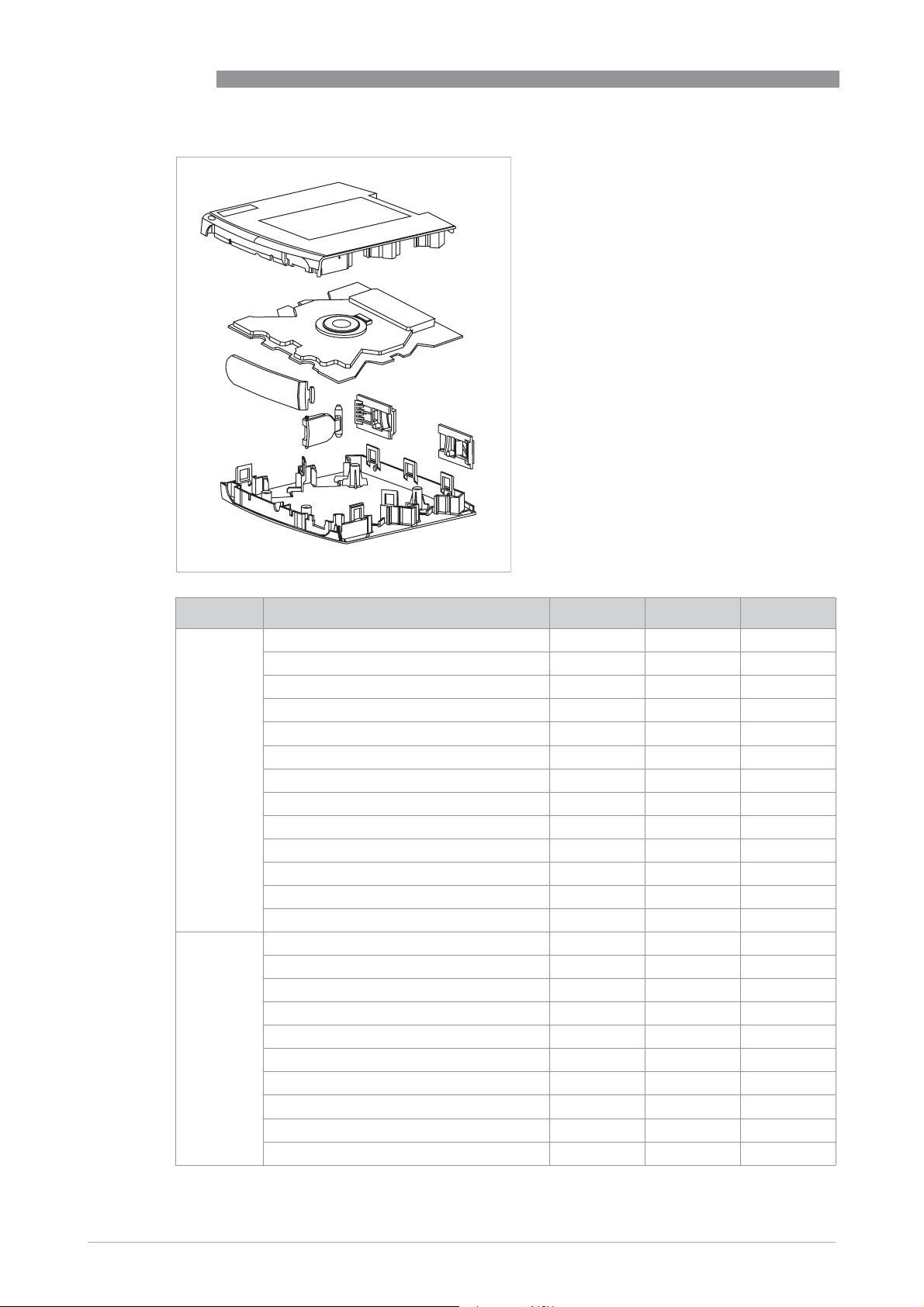
To achieve reliability and quality performance of the product IPAQ R330/R330X is encapsulated
in casting polymer plastic resulting in that dismantling of the IPAQ R330/R330X is not possible
except the housing, which is sorted as plastic. The content of the IPAQ R330/R330X can be found
in the following table.
www.inor.com09/2020 - 4007317401 – MA IPAQ 330 R02 en
35
Page 36
6
SERVICE
IPAQ C330/R330
Material CAS Weight [g] Weight [%]
Thermoplastic NA 45.1 70.7
Stainless steel NA 4.3 6.7
Brass NA 3.2 5.0
Zinc 7440-66-6 0.3 0.5
Silicone 7440-21-3 0.8 1.3
Epoxy NA 8.1 12.7
Lead free solder NA 0.3 0.5
Copper 7440-50-8 0.9 1.4
Polyester NA 0.2 0.3
Nickel 7723-14-0 0.3 0.5
Alumina (Al2O3) 1344-28-1 0.1 0.2
Gold (Au) 7444-57-6 0.1 0.2
Barium titanat (BaTiO3) 12047-27-7 0.1 0.2
RoHS Polybrominated diphenyl Ethers (PBDE) NA 0 0
Cadmium (Cd) 7440-43-9 0 0
Mercury (Hg) 7439-97-6 0 0
Lead (Pb) 7440-31-7 0 0
Chrome VI (Cr VI) 7440-47-3 0 0
Polybrominated biphenyls (PBB) NA 0 0
Bis (2-ethylhexil) phthalate (DEHP) 117-81-7 0 0
Butyl benzyl phthalate (BBP) 85-68-7 0 0
Dibutyl phthalate (DBP) 84-74-2 0 0
Diisobutyl phthalate (DIBP) 84-69-5 0 0
36
www.inor.com
09/2020 - 4007317401 – MA IPAQ 330 R02 en
Page 37

IPAQ C330/R330
6.5.5 Packaging of IPAQ C330/C330X and R330/R330X
The products are delivered to the customers in corrugated cardboard boxes, which protect
products against moisture and provides sustainable packaging solutions.
SERVICE
6
www.inor.com09/2020 - 4007317401 – MA IPAQ 330 R02 en
37
Page 38
7
TECHNICAL DATA
7.1 Measuring principles
The kind of the measuring principle depends on the measuring insert that you combine with the
transmitter. In matters of the thermometer type the manufacturer offers two different
measuring inserts, either with a resistance thermometer or with a thermocouple. This
transmitter supports both types.
7.1.1 Resistance temperature sensor
The measuring insert with a temperature-sensitive sensor made from a platinum(Pt) RTD,
whose value at 0°C / +32°F is 100 Ω. That is where the name "Pt100" comes from.
It is generally valid that the electric resistance of metals increases according to a mathematical
function as the temperature rises. This effect is taken advantage of by resistance temperature
sensors to measure temperature. The "Pt100" temperature sensors features a measuring
resistance with defined characteristics, standardised in IEC 60751. The same is true for the
tolerances. The average temperature coefficient of a Pt100 is 3.85 x 10
0...+100°C / +32...+212°F.
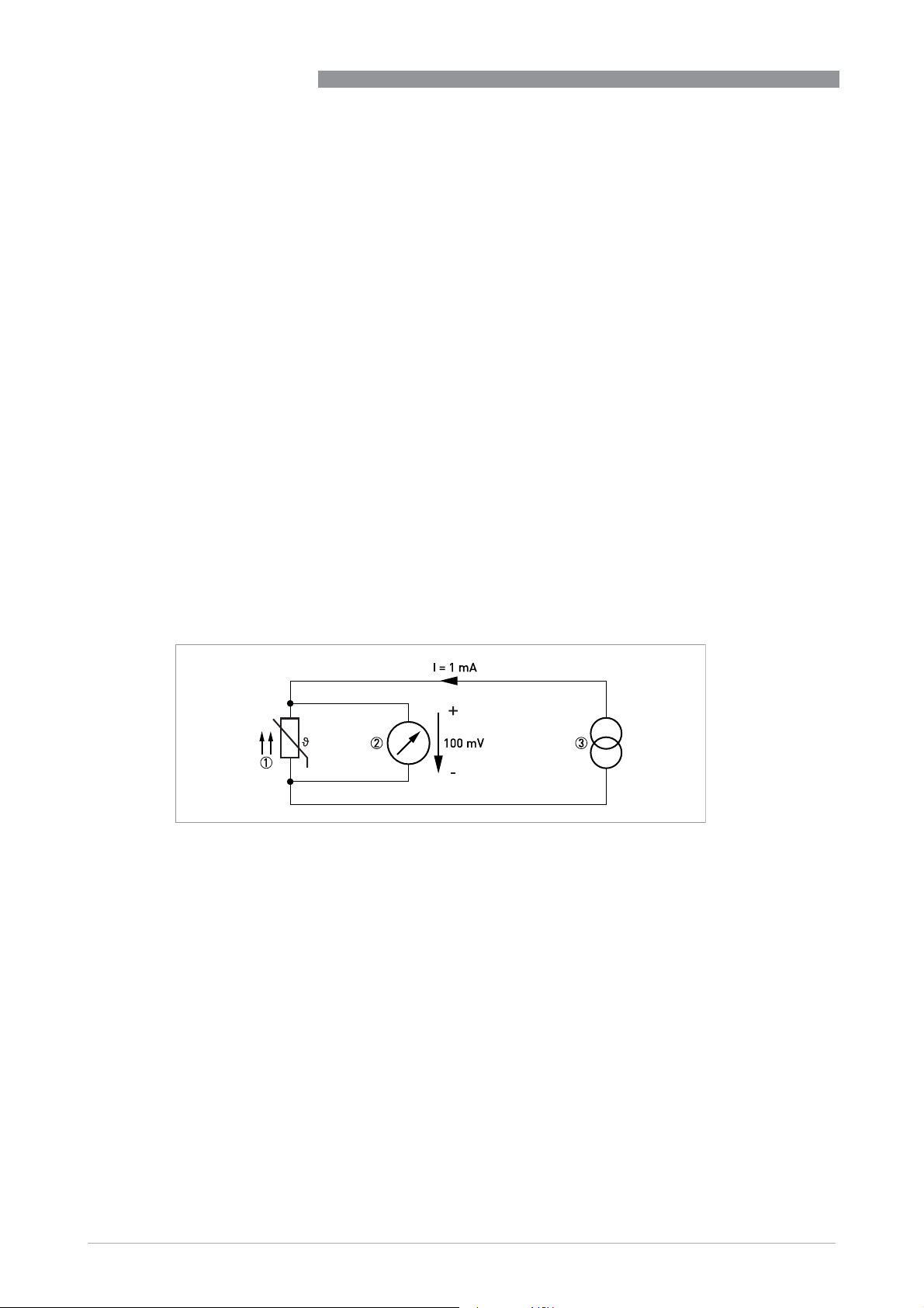
During operation, a constant current I (≤ 1 mA) flows through the Pt100 RTD, which brings about
a voltage drop U. The resistance R is calculated using Ohm's Law (R=U/I). As the voltage drop U
at 0°C / +32°F is 100 mV, the resulting resistance of the Pt100 temperature assembly is
100 Ω (100 mV / 1 mA = 100 Ω).
IPAQ C330/R330
-3K-1
in the range from
38
Figure 7-1: Pt100 resistance temperature sensor at 0°C/ +32°F, schematic
1 Pt100 RTD
2 Voltage meter
3 Current source
www.inor.com
09/2020 - 4007317401 – MA IPAQ 330 R02 en
Page 39
IPAQ C330/R330
7.1.2 Thermocouples
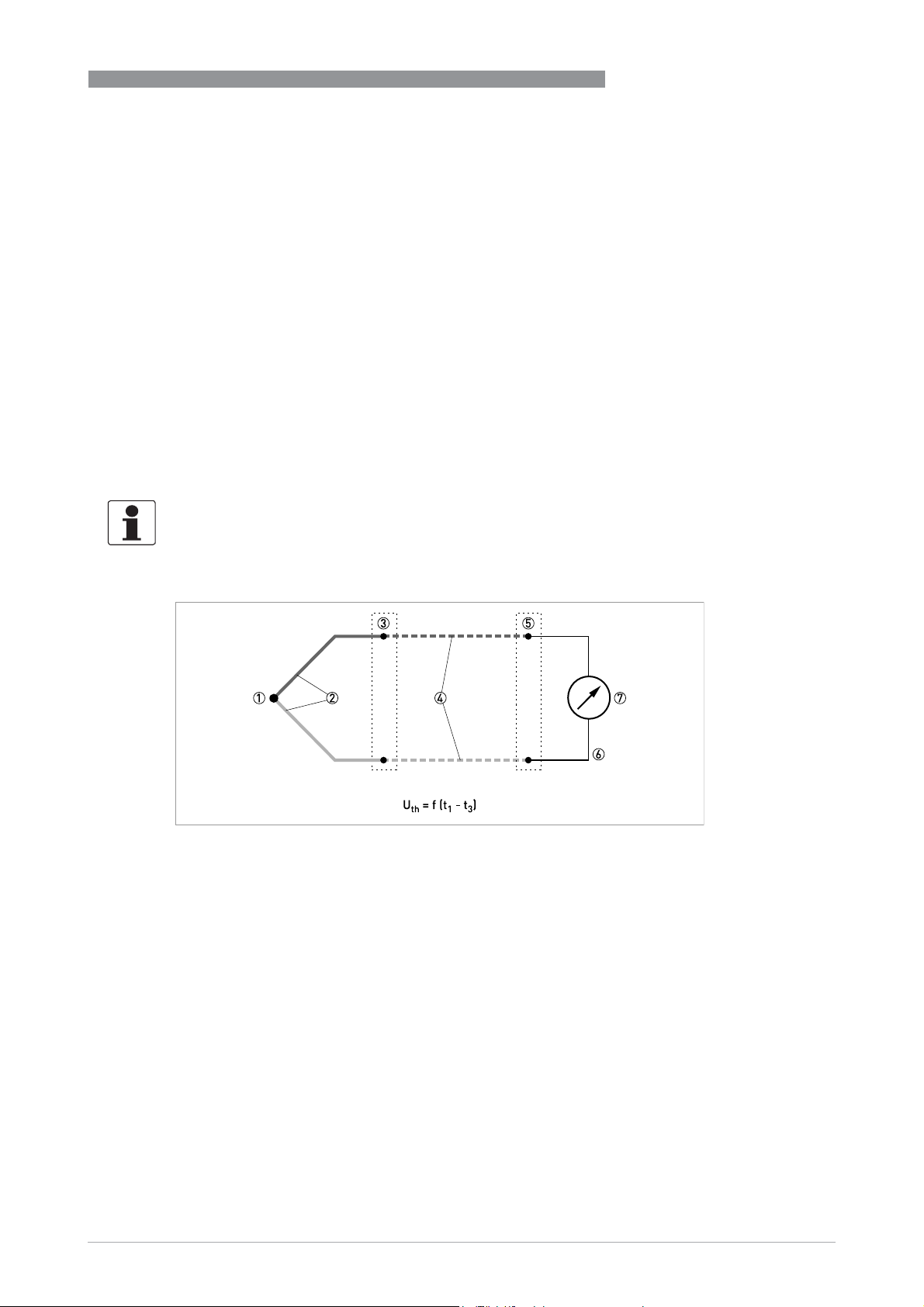
The thermocouple features two electric conductors made from different metals, connected at
one end. Each free end is connected to a compensation cable which is then connected to a
millivolt meter. This circuitry forms a "thermal circuit". The point at which the two electric
conductors connect is called the measuring point and the point at which the compensation
cables connect to the conductors of the millivolt meter is called the cold junction.
If the measuring point of this thermal circuit is heated up, a small electrical voltage (thermal
voltage) can be measured. If, however, the measuring point and the cold junction are at the same
temperature, no thermoelectric voltage is generated. The degree of thermoelectric voltage, also
known as electromotive force (EMF), depends on the thermocouple material and the extent of
the temperature difference between the measuring point and the cold junction. It can be
measured using the millivolt meter with no auxiliary power.
Simply put, the thermocouple behaves like a battery, the voltage of which also increases as the
temperature rises.
The characteristic curves and tolerances of commercially available thermocouples are
standardised in IEC 60584.
TECHNICAL DATA
7
Figure 7-2: Thermocouple measuring circuit, schematic
1 Measuring point t
2 Thermocouple
3 Transition junction t
4 Compensation cable / extension cable
5 Reference junction t
6 Copper conductor
7 Voltage meter U
(hot junction)
1
2
(cold junction)
3
th
www.inor.com09/2020 - 4007317401 – MA IPAQ 330 R02 en
39
Page 40
7
TECHNICAL DATA
IPAQ C330/R330
7.2 Technical data
•
The following data is provided for general applications. If you require data that is more
relevant to your specific application, please contact us or your local sales office.
•
Additional information (certificates, special tools, software,...) and complete product
documentation can be downloaded free of charge from the website.
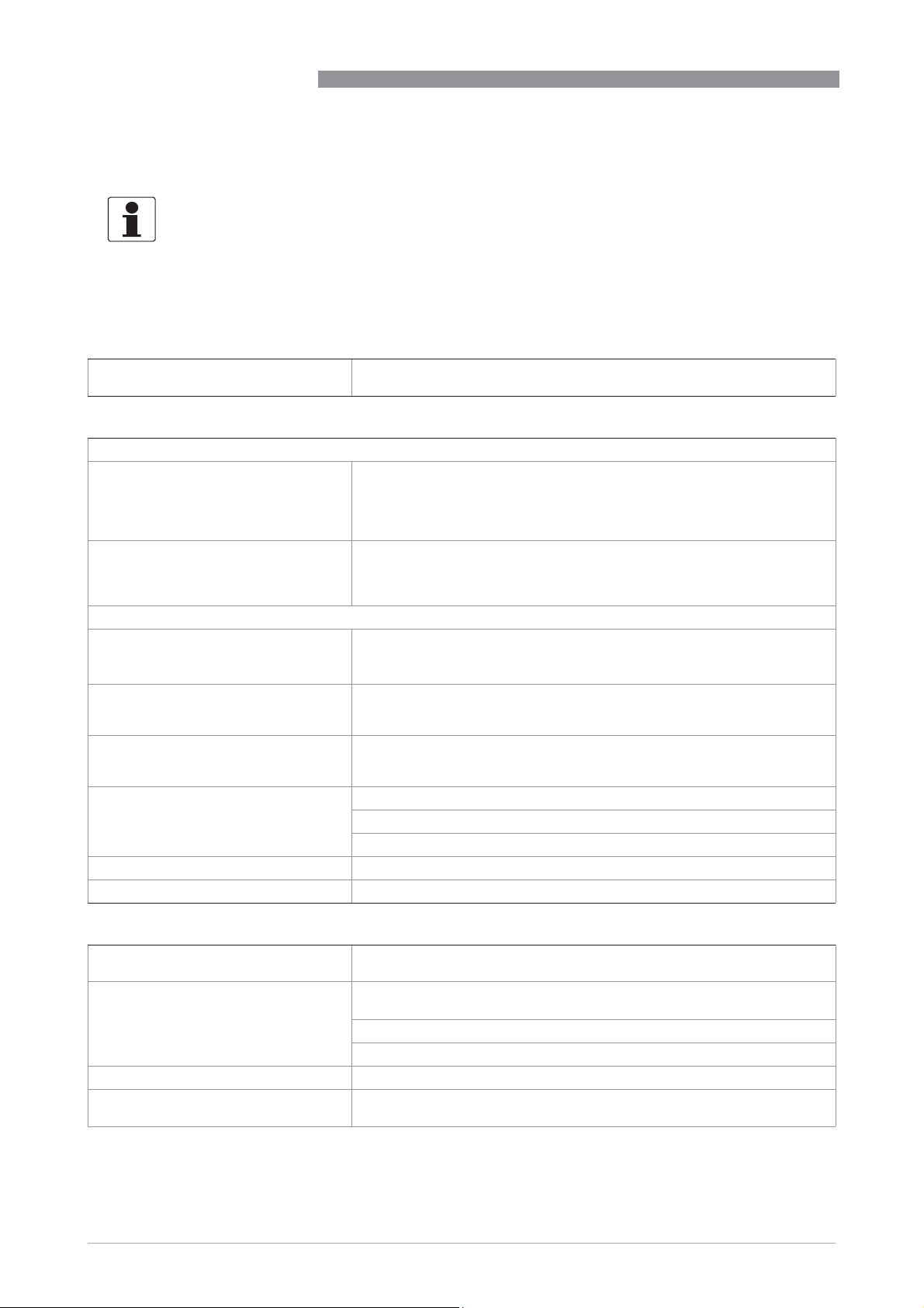
Measuring system
Application range Temperature measurements of solids, liquids and gases in industrial
Design
Versions
Versions
VersionsVersions
C330
R330
Features
Features
FeaturesFeatures
®
NFC
Sensor matching A matching to a calibrated temperature sensor can easily be performed by
Customized linearization For resistance and mV inputs, either a 50-point customized linearization
PC programmable Measuring ranges are set from PC.
Runtime counter Hour counter for elapsed operational time.
Simulated output Fixed current output during a maximum time of 15 minutes.
environment.
In-head transmitters which are intended for installation in a DIN B-head or
larger according
This transmitter is optionally available in an intrinsically safe version
(zone 0, 1 and 2 / DIV 1 and 2) for installation in potentially explosive
atmospheres.
Rail-mount transmitters which are inten
according to DIN 50022 / EN 60715, 35 mm / 1.38".
The transmitter is optionally available in an intrinsically safe version (zone 0,
1 and 2 / DIV 1 and 2) for installation in potentially explosive atmospheres.
NFC® enables wireless communication and configuration between
transmitter and a portable device such a smartphone.
NFC applies only to later versions of IPAQ 330
entering the sensor deviation in the low and high ends of the measuring
ranges.
table or via Callendar-Van Dusen (applies only to RTD, α = 0.00385)
constants can provide a correct process value.
Full accuracy is provided without any need for calibration.
Configuration without external power.
to DIN EN 50446.
ded for installation on a DIN-rail
Measuring accuracy
Accuracy & stability Typical accuracy is max. of ±0.08°C or ±0.08% of span.(Pt100, 3- or 4-wire
Ambient temperature influence RTD and thermocouple: for detailed information refer to
Supply voltage influence <±0.005% of span per V
Long-term drift Max. of ±0.02°C or ±0.02% of span per year
40
connection)
RTD and T/C
accuracy table
Resistance: ±0.01% < 4000 Ω (2000 Ω at 2-wire) < ±0.02% of span per °C
Voltage: ±0.01% of span per °C
on page 49.
www.inor.com
09/2020 - 4007317401 – MA IPAQ 330 R02 en
Page 41
IPAQ C330/R330
TECHNICAL DATA
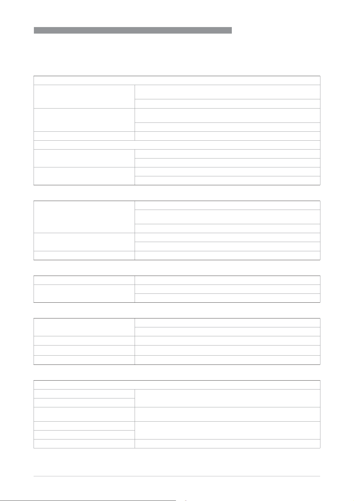
Operating conditions
Temperature
Temperature
TemperatureTemperature
In-head transmitter Operating and storage temperature:
Rail-mount transmitter Operating and storage temperature:
Humidity 0...95% RH (non-condensing)
Protection category
Protection category
Protection categoryProtection category
In-head transmitter Housing: IP65
Rail-mount transmitter Housing: IP20
Operating and storage temperature:
Operating and storage temperature:Operating and storage temperature:
Standard version: -40...+85°C / -40...+185°F
IS version: For permitted ambient temperature
Operating and storage temperature:
Operating and storage temperature:Operating and storage temperature:
Standard version: -40...+85°C / -40...+185°F
IS version: For permitted ambient temperature
Terminals: IP00
Terminals: IP20
range, see page 46
range, see page 46
Installation conditions
Mounting In-head transmitter: DIN B-head or larger, DIN-rail (with adapter)
Rail-mount transmitter: DIN-rail according to DIN 50022 / EN 60715,
35 mm / 1.38"
For detailed information refer to
Weight In-head transmitter: 35 g / 0.08 lb
Rail-mount transmitter: 70 g / 0.15 lb
Dimensions For detailed information refer to
Installation
Dimensions
on page 14.
on page 45.
7
Materials
Housing PC/ABS + PA
Flammability according to UL In-head transmitter: V0
Rail-mount transmitter: V0/HB
Electrical connections
Power supply Standard version: 8.0...36 VDC
IS version: 8.0...30 VDC
Isolation Galvanically isolated (in-out), 1500 VAC, 1 minute
Connection
Reverse Polarity Protection Yes
Single/stranded wires: max. 1.5 mm2/ AWG 16
Inputs / Outputs
Input - RTD
Input - RTD
Input - RTDInput - RTD
Pt100 (IEC 60751, α = 0.00385) -200...+850°C / -328...+1562°F
Pt100 (JIS C1604-1981, α = 0.003916)
PtX (10 ≤ X ≤ 1000)
(IEC 60751, α = 0.00385)
Ni100 (DIN 43760) -60...+250°C / -76...+482°F
Ni120 (Edison No. 7)
Ni1000 (DIN 43760) -50...+180°C / -58...+356°F
The upper range depends on the X value, max. input temperature
corresponding to 4000 Ω.
www.inor.com09/2020 - 4007317401 – MA IPAQ 330 R02 en
41
Page 42

7
TECHNICAL DATA
Cu10 (Edison Copper Windings No. 15) -50...+200°C / -58...+392°F
Sensor current ≤300 μA
Maximum sensor wire resistance 3-wire and 4-wire connection: 50 Ω/wire
Adjustment Minimum span 10°C/ 18°F
Input - resistance / potentiometer
Input - resistance / potentiometer
Input - resistance / potentiometerInput - resistance / potentiometer
Range (resistance) 0...10000 Ω
Range (potentiometer) 100...10000 Ω
Zero adjustment Within range
Max offset adjustment 50% of selected max. value
Minimum span 10 Ω
Sensor current ≤300 μA
Customized linearization Up to 50 points
Maximum sensor wire resistance In-head transmitter: 50 Ω/wire
Input - thermocouples
Input - thermocouples
Input - thermocouplesInput - thermocouples
T/C type B - Pt30Rh-Pt6Rh (IEC 60584) 400...+1800°C / +752...+3272°F
T/C type C - W5Re-W26Re (ASTM E 988) 0...+2315°C / 32...+4199°F
T/C type D - W3Re-W25Re (ASTM E 988) 0...+2315°C / 32...+4199°F
T/C type E - NiCr-CuNi (IEC 60584) -270...+1000°C / -454...+1832°F
T/C type J - Fe-CuNi (IEC 60584) -210...+1200°C / -346...+2192°F
T/C type K - NiCr-NiAl (IEC 60584) -270...+1300°C / -454...+2372°F
T/C type N - NiCrSi-NiSi (IEC 60584) -270...+1300°C / -454...+2372°F
T/C type R - Pt13Rh-Pt (IEC 60584) -50...+1750°C / -58...+3182°F
T/C type S - Pt10Rh-Pt (IEC 60584) -50...+1750°C / -58...+3182°F
T/C type T - Cu-CuNi (IEC 60584) -270...+400°C / -454...+752°F
Input impedance >10 MΩ
Maximum wire loop resistance In-head transmitter (including T/C sensor): 5 kΩ
Cold Junction Compensation (CJC) Internal, external (Pt100) or fixed
Input - voltage
Input - voltage
Input - voltageInput - voltage
Range -10...+1000 mV
Zero adjustment Within range
Minimum span 2mV
Customized linearization Up to 50 points
Input impedance >10 MΩ
Maximum wire loop resistance In-head transmitter: 5 kΩ
Output
Output
OutputOutput
Output signal 4...20 mA, 20...4 mA; temperature, resistance or voltage linear, customized
Permissible load (Supply voltage-8,0)/0.022
NAMUR compliance Output limits and failure currents according to NAMUR NE 43
2-wire connection: Compensation for 0 to 100 Ω loop resistance
Sensor error compensation ±10% of span for span <50°C/ 90°F, otherwise
±5°C/ ±9°F
Rail-mount transmitter: 50 Ω/wire
Field transmitter (including T/C sensor): 10 kΩ
Field transmitter / Switch room transmitter: 10 kΩ
linearization possible.
IPAQ C330/R330
42
www.inor.com
09/2020 - 4007317401 – MA IPAQ 330 R02 en
Page 43

IPAQ C330/R330
Adjustable filtering level 0.17...90 s, (default 1.4s) (3-wire RTD)
Monitoring Sensor break and short circuit monitoring, selectable, upscale ≥21.0 mA or
Configuration
Configuration
ConfigurationConfiguration
ConSoft The PC configuration software, ConSoft, is a versatile and user-friendly tool
INOR connect The app INOR Connect for portable devices (smartphones) is a versatile and
downscale ≤3.6 mA action, individually configurable.
for transmitter configuration.
ConSoft is compatible with Windows XP/Vista/7/8/8.1/10
ConSoft is part of the complete configuration kit, which also contains a USB
interface and necessary cables.
Full functionality of the transmitter is achieved with ConSoft program
version 3.4.0 or later and the firmware in the USB Interface must have a
version number 1.2.07 or later.
user-friendly tool for wireless configuration through Bluetooth
technology.
Communication via Bluetooth
ICON-BT, which can be ordered from the manufacturer.
®
requires the Bluetooth® interface -
TECHNICAL DATA
®
or NFC®
Approvals and certifications
CE The device fulfils the statutory requirements of the EU directives.
Ex approvals
Ex approvals
Ex approvalsEx approvals
Standard version Without
Intrinsically safe (IS) version Refer to Ex approvals
Other standards and approvals
Other standards and approvals
Other standards and approvalsOther standards and approvals
Electromagnetic compatibility Directive: 2014/30/EU
RoHS Directive: 2011/65/EU
Vibration resistance According to IEC 60068-2-6, test Fc, 10...2000 Hz,
Radio Equipment Directive This product contains NFC communication and conforms to the
The manufacturer certifies that these requirements have been met by
applying the CE marking.
Ex approvals in the separate table below.
Ex approvalsEx approvals
Harmonized standards: EN 61326-1 and EN 61326-2-3
NAMUR NE 21
EN 61326-1 and -2-3: Criteria A
NE 21: <0.5% of span
Harmonized standard: EN 50581
10 g for in-head mounted / 5 g for rail mounted transmitter
requirements of the Radio Equipment Directive (RED) 2014/53/EU
7
www.inor.com09/2020 - 4007317401 – MA IPAQ 330 R02 en
43
Page 44

7
TECHNICAL DATA
Ex approvals
C330X (intrinsically safe), part no. 70C330X010 and 70C330X012
C330X (intrinsically safe), part no. 70C330X010 and 70C330X012
C330X (intrinsically safe), part no. 70C330X010 and 70C330X012C330X (intrinsically safe), part no. 70C330X010 and 70C330X012
ATEX KIWA 16ATEX0038 X II 1 G Ex ia IIC T6...T4 Ga
IECEx IECEx KIWA 16.0016X Ex ia IIC T6...T4 Ga
USA FM17US0283X
Canada FM17CA0144X
R330X (intrinsically safe), part no. 70R330X010 and 70R330X012
R330X (intrinsically safe), part no. 70R330X010 and 70R330X012
R330X (intrinsically safe), part no. 70R330X010 and 70R330X012R330X (intrinsically safe), part no. 70R330X010 and 70R330X012
ATEX KIWA 16ATEX0040 X II 1 G Ex ia IIC T6...T4 Ga
IECEx IECEx KIWA 16.0018X Ex ia IIC T6...T4 Ga
USA FM17US0283X
Canada FM17CA0144X
Cl I DIV 1 GP A-D, T6...T4
Zn 0 AEx/Ex ia IIC T6...T4 Ga
Cl I
Cl I DIV 1 GP A-D, T6...T4
Zn 0 AEx/Ex ia IIC T6...T4 Ga
Cl I
IPAQ C330/R330
44
www.inor.com
09/2020 - 4007317401 – MA IPAQ 330 R02 en
Page 45
IPAQ C330/R330
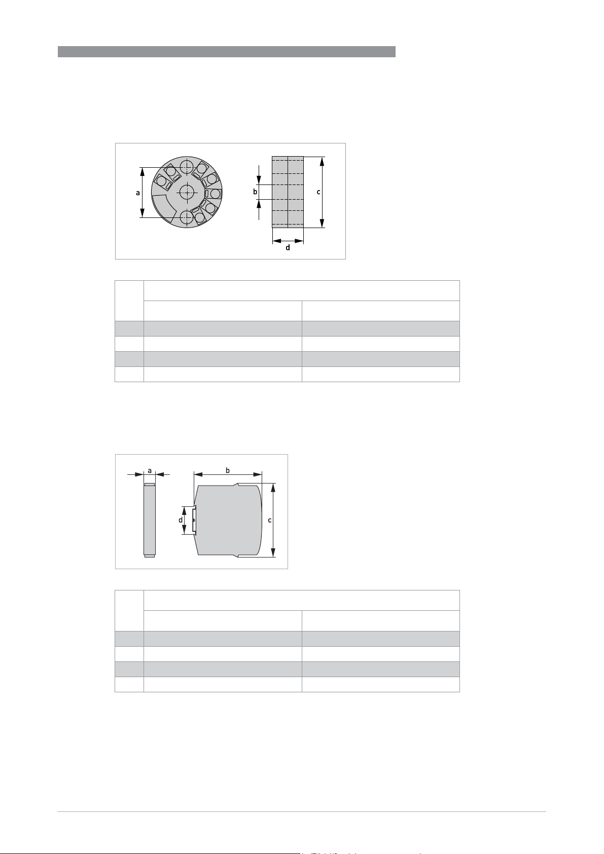
7.3 Dimensions
In-head transmitter
In-head transmitter
In-head transmitterIn-head transmitter
a 33.0 1.30
b 7.0 0.28
c 44.5 1.75
d 19.7 0.78
Dimensions
[mm] [inch]
TECHNICAL DATA
7
Rail-mount transmitter
Rail-mount transmitter
Rail-mount transmitterRail-mount transmitter
Dimensions
[mm] [inch]
a 17.5 0.69
b 81.3 3.20
c 90.0 3.54
d 35 1.38
www.inor.com09/2020 - 4007317401 – MA IPAQ 330 R02 en
45
Page 46
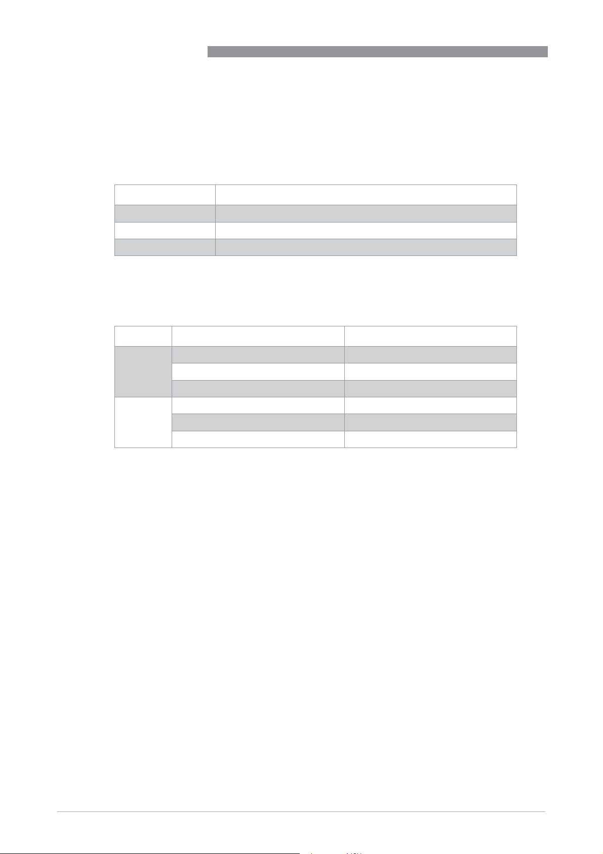
7
TECHNICAL DATA
IPAQ C330/R330
7.4 Temperature data for areas with potentially explosive atmospheres
Intrinsically safe in head and rail mount transmitter
C330X, part no. 70C330X010
R330X, part no. 70R330X010
Temperature class Allowed ambient temperature
T6 -40°C ≤ Ta ≤ +60°C / -40°F ≤ Ta ≤ +140°F
T5 -40°C ≤ Ta ≤ +75°C / -40°F ≤ Ta ≤ +167°F
T4 -40°C ≤ Ta ≤ +85°C / -40°F ≤ Ta ≤ +185°F
C330X, part no. 70C330X012
R330X, part no. 70R330X012
Pi Temperature class Allowed ambient temperature
900 mW T6 -40°C ≤ Ta ≤ +55°C / -40°F ≤ Ta ≤ +131°F
T5 -40°C ≤ Ta ≤ +70°C / -40°F ≤ Ta ≤ +158°F
T4 -40°C ≤ Ta ≤ +85°C / -40°F ≤ Ta ≤ +185°F
700 mW T6 -40°C ≤ Ta ≤ +60°C / -40°F ≤ Ta ≤ +140°F
T5 -40°C ≤ Ta ≤ +75°C / -40°F ≤ Ta ≤ +167°F
T4 -40°C ≤ Ta ≤ +85°C / -40°F ≤ Ta ≤ +185°F
46
www.inor.com
09/2020 - 4007317401 – MA IPAQ 330 R02 en
Page 47
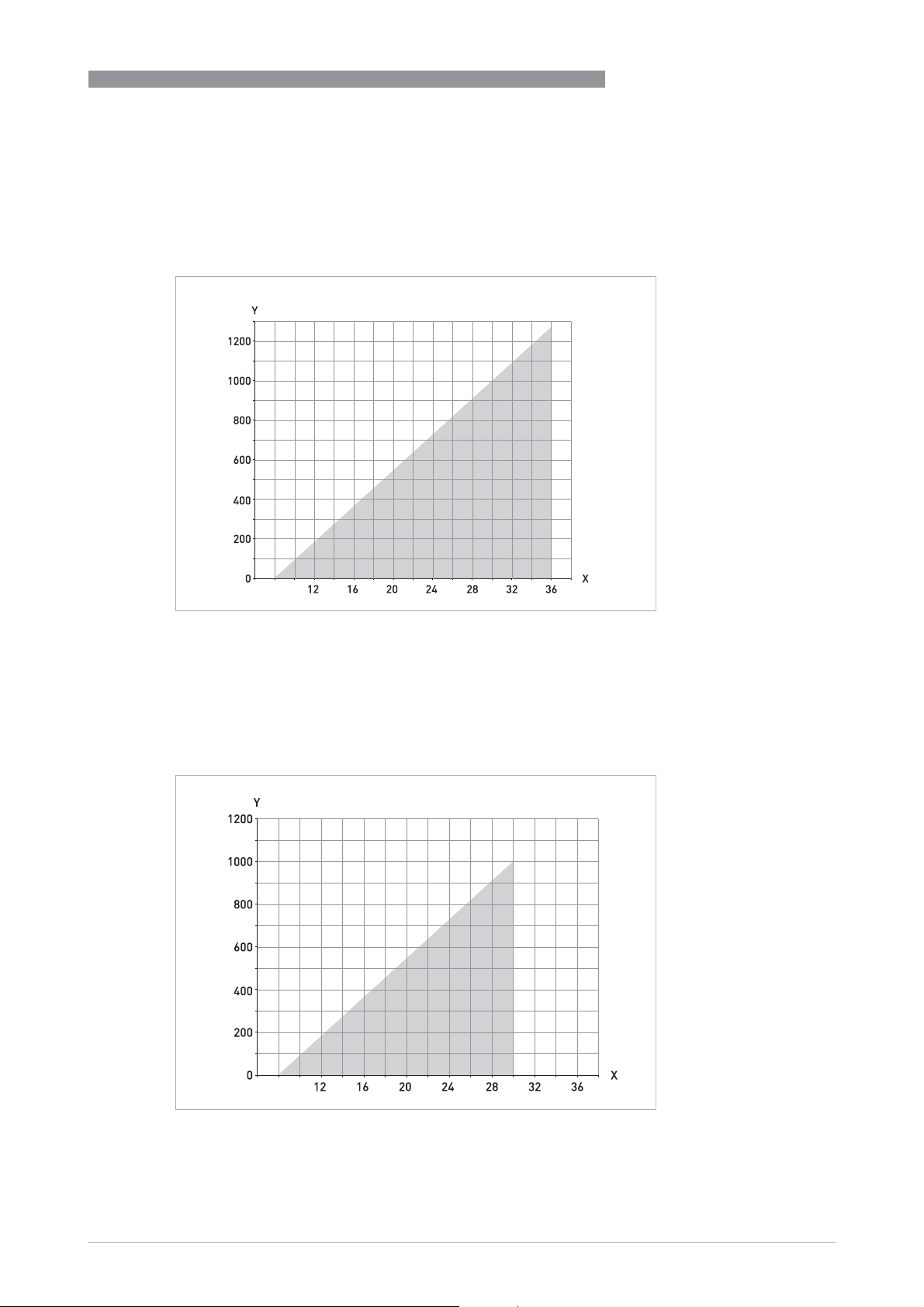
IPAQ C330/R330
7.5 Output load diagram
Formula for the maximum permissible output load:
permissible R
Standard transmitter
[Ω] = (U-8.0)/0.022
Load
TECHNICAL DATA
7
8
Figure 7-3: Output load diagram
X: Power supply U [VDC]
Y: Total output load R [Ω]
Formula for the maximum permissible output load:
permissible R
[Ω] = (U-8.0)/0.022
Load
Intrinsically safe transmitter
8
Figure 7-4: Output load diagram
X: Power supply U [VDC]
Y: Total output load R [Ω]
www.inor.com09/2020 - 4007317401 – MA IPAQ 330 R02 en
47
Page 48
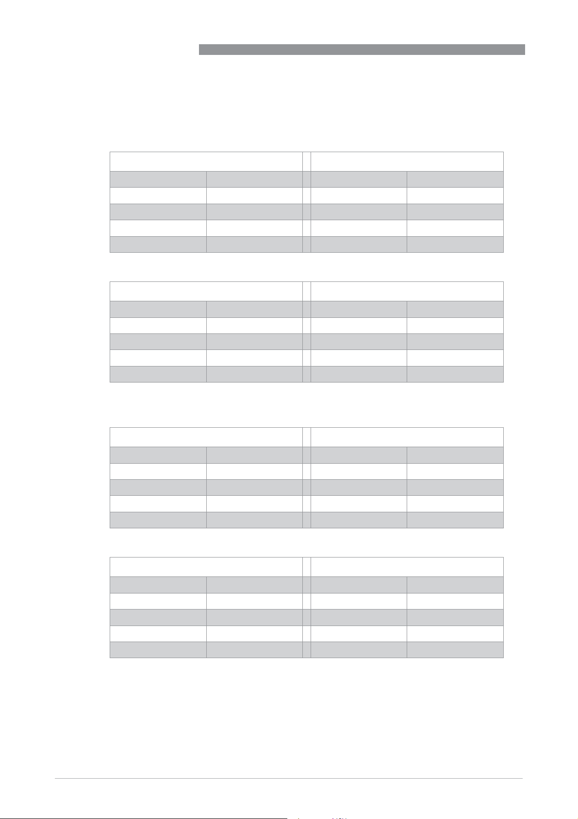
7
TECHNICAL DATA
7.6 Electrical data for outputs and inputs
In-head transmitter
In-head transmitter
In-head transmitterIn-head transmitter
Intrinsically safe transmitter, C330X - Part number 70C330X010
Output terminals 6, 7 Input terminals 1, 2, 3, 4
IPAQ C330/R330
Ui = V
Ii = I
Pi = P
L
i
C
i
max
max
max
≤ 30 VDC U0 = U
≤ 100 mA I0 = I
≤ 900 mW P
20 μH L
23.1 nF C
0
0
0
0C
SC
Intrinsically safe transmitter, C330X - Part number 70C330X012
Output terminals 6, 7 Input terminals 1, 2, 3, 4
Ui = V
max
Ii = I
max
Pi = P
max
L
i
C
i
Rail-mount transmitter
Rail-mount transmitter
Rail-mount transmitterRail-mount transmitter
≤ 30 VDC Uo = U
≤ 100 mA Io = I
≤ 900 mW P
20 μH L
23.1 nF C
o
o
o
0C
SC
Intrinsically safe transmitter, R330X - Part number 70R330X010
Output terminals 21, 22 Input terminals 1, 2, 3, 4
Ui = V
Ii = I
Pi = P
L
i
C
i
max
max
max
≤ 30 VDC U0 = U
≤ 100 mA I0 = I
≤ 900 mW P
20 μH L
23.1 nF C
0
0
0
0C
SC
≤ 30 VDC
≤ 54 mA
≤ 405 mW
11 mH
38.1 nF
≤ 6.5 VDC
≤ 11.7 mA
≤ 19.1 mW
400 mH
24 μF
≤ 30 VDC
≤ 54 mA
≤ 405 mW
11 mH
38.1 nF
48
Intrinsically safe transmitter, R330X - Part number 70R330X012
Output terminals 21, 22 Input terminals 1, 2, 3, 4
Ui = V
Ii = I
Pi = P
L
i
C
i
max
max
max
≤ 30 VDC Uo = U
≤ 100 mA Io = I
≤ 900 mW P
20 μH L
23.1 nF C
www.inor.com
o
o
o
0C
SC
09/2020 - 4007317401 – MA IPAQ 330 R02 en
≤ 6.5 VDC
≤ 11.7 mA
≤ 19.1 mW
400 mH
24 μF
Page 49

IPAQ C330/R330
TECHNICAL DATA
7.7 RTD and T/C accuracy table
Typical accuracy ±0.08% of span, max. of ±0.1 K or ±0.1% of span.(Pt100, 3- or 4-wire connection)
Conformance level 95% (2σ)
CJC = Cold Junction Compensation
Accuracies in °C
Input type Temp. range Min. span Accuracy (maximum of) Temp. influence
[°C] [°C] [°C]
(Dev. from ref. temp. 20°C)
7
RTD Pt100 -200...+850 10 ±0.08°C or ±0.08% of span
RTD PtX
2
Corresp. to max.
10 ±0.1°C or ±0.1% of span
1
1
±0.01% of span per °C
±0.01% of span per °C
4kΩ
RTD Ni100 -60...+250 10 ±0.1°C or ±0.1% of span
RTD Ni120 -60...+250 10 ±0.1°C or ±0.1% of span
RTD Ni1000 -50...+180 10 ±0.1°C or ±0.1% of span
RTD Cu10 -50...+200 83 ±1.5°C or ±0.2% of span
T/C type B +400...+1800 700 ±1.0°C or ±0.2% of span
T/C type C 0...+2315 200 ±1.0°C or ±0.2% of span
T/C type D 0...+2315 200 ±1.0°C or ±0.2% of span
T/C type E -270...+1000 50 ±0.5°C or ±0.1% of span
T/C type J -210...+1200 50 ±0.5°C or ±0.1% of span
T/C type K -270...+1300 50 ±0.5°C or ±0.1% of span
T/C type N -100...+1300 100 ±0.5°C or ±0.1% of span
T/C type N -270...-100 100 ±1.0°C
4
T/C type R -50...+1750 300 ±1.0°C or ±0.1% of span
T/C type S -50...+1750 300 ±1.0°C or ±0.1% of span
T/C type T -270...+400 50 ±0.25°C or ±0.2% of span
1 Valid for 3- and 4-wire connection. For factory settings Pt100, 3-wire connection, 0..100°C applies ±0.05 °C.
2 (10 ≤ X ≤ 1000)
3 For 2-wire connection and span >2000 Ω applies ±0.02% of span per °C
4 CJC error not included. ≤ 0.5°C within ambient temperature range
1
1
1
1
4
4
4
4
4
4
4
4
4
±0.01% of span per °C
±0.01% of span per °C
±0.01% of span per °C
±0.02% of span per °C
±0.01% of span per °C
±0.01% of span per °C
±0.01% of span per °C
±0.01% of span per °C
±0.01% of span per °C
±0.01% of span per °C
±0.01% of span per °C
±0.1% of span per °C
±0.01% of span per °C
±0.01% of span per °C
4
±0.01% of span per °C
3
3
www.inor.com09/2020 - 4007317401 – MA IPAQ 330 R02 en
49
Page 50

7
TECHNICAL DATA
IPAQ C330/R330
Accuracies in °F
Input type Temp. range Min. span Accuracy (maximum of) Temp. influence
[°F] [°F] [°F]
(Dev. from ref. temp. 68°F)
RTD Pt100 -328...+1562 18 ±0.14°F or ±0.08% of span
RTD PtX
2
Corresp. to max.
18 ±0.18°F or ±0.1% of span
1
1
4kΩ
RTD Ni100 -76...+482 18 ±0.18°F or ±0.1% of span
RTD Ni120 -76...+482 18 ±0.18°F or ±0.1% of span
RTD Ni1000 -58...+356 18 ±0.18°F or ±0.1% of span
RTD Cu10 -58...+392 149 ±2.7°F or ±0.2% of span
T/C type B +752...+3272 1260 ±1.8°F or ±0.1% of span
T/C type C +32...+4199 360 ±1.8°F or ±0.1% of span
T/C type D +32...+4199 360 ±1.8°F or ±0.1% of span
T/C type E -454...+1832 90 ±0.9°F or ±0.1% of span
T/C type J -346...+2192 90 ±0.9°F or ±0.1% of span
T/C type K -454...+2372 90 ±0.9°F or ±0.1% of span
T/C type N -148...+2372 180 ±0.9°F or ±0.1% of span
T/C type N -454...-148 180 ±1.8°F
4
T/C type R -58...+3182 540 ±1.8°F or ±0.1% of span
T/C type S -58...+3182 540 ±1.8°F or ±0.1% of span
T/C type T -454...+752 90 ±0.9°F or ±0.1% of span
1 Valid for 3-wire, 4-wire connection. For factory settings Pt100, 3-wire, 32-212 °F applies ±0.09 ° F.
2 (10 ≤ X ≤ 1000)
3 For 2-wire connection and span >2000 Ω applies ±0.02% of span per 1.8° F
4 CJC error not included. ≤ 0.9°F within ambient temperature range
1
1
1
1
4
4
4
4
4
4
4
4
4
4
±0.006% of span per °F
±0.006% of span per °F
±0.006% of span per °F
±0.006% of span per °F
±0.006% of span per °F
±0.006% of span per °F
±0.006% of span per °F
±0.006% of span per °F
±0.006% of span per °F
±0.006% of span per °F
±0.006% of span per °F
±0.006% of span per °F
±0.006% of span per °F
±0.18% of span per °F
±0.006% of span per °F
±0.006% of span per °F
±0.006% of span per °F
3
3
50
www.inor.com
09/2020 - 4007317401 – MA IPAQ 330 R02 en
Page 51

IPAQ C330/R330
8.1 Installation and control drawings
IPAQ Part Number Control drawing
C330X
1
C330X
2
R330X
1
R330X
2
1 Without NFC interface
2 With NFC interface
70C330X010 4005488501
70C330X012 4005488502
70R330X010 4005499601
70R330X012 4005499602
APPENDIX
8
www.inor.com09/2020 - 4007317401 – MA IPAQ 330 R02 en
51
Page 52
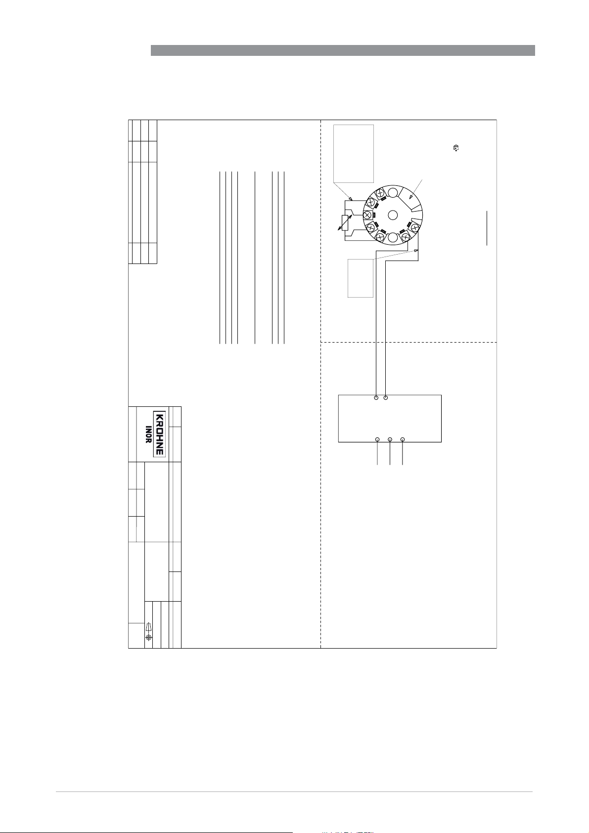
8
APPENDIX
Revision
Date
Comment
Approved by:
Rev 1
161123
First release revision
GP
Rev 2 170120
Changed value for Co
GP
Rev 3
180615
cFMus added, Co group IIA=1000 nF
GP
Isolation in-out 1500 VAC (Signal isolation)
Output Analog 4-20 mA, temperature linear
Power supply 8 to 30 VDC for IPAQ C330X
Sensor short circuit Upscale (21.0 mA) or downscale (≥3.6 mA)
Sensor break Upscale (21.0 mA) or downscale (≥3.6 mA)
Range configuration
Measuring ranges Multifunctional with wide measuring ranges
Sensor monitoring
Configuration PC-programmable
This drawing is property of Inor Process AB, Malmö, Sweden, without whose permission
it may not be copied, and the contents thereof must not be imparted to third party nor be
used for any unautherized purpose. Contravention will be prosecuted.
Input RTD, T/C, mV and Ohm
Connection type 2-, 3-, and 4-wire. Pot/Slide wire
Data (short form)
IIC A/B 38.1 11
IIB C 530 45
IIA D 1000 90
Group Co=Ca Lo=La
(nF) (mH)
(RTD, T/C etc.)
Sensor
Li=20μH
Ci = 23.1 nF
IPAQ C330/R330
Europe:
KIWA 16ATEX0038 X
IECEx KIWA 16.0016X
CE 0539 II 1 G Ex ia IIC T6...T4 Ga
T4: -40 °C ≥ Ta ≥ +85 °C
T5: -40 °C ≥ Ta ≥ +75 °C
Po=405 mW
Uo=Voc=30 V
Io=Isc=54 mA
5
4
3
+
6
2
-
7
1
Pi=Pmax=900 mW
Ui=Vmax=30 V
Ii=Imax=100 mA
T6: -40 °C ≥ Ta ≥ +60 °C
-40 °F ≥ Ta ≥ +140 °F
T6: -40 °C ≥ Ta ≥ +60 °C
USB Connection
Hazardous (Classified) Location
IPAQ C330X
North America:
USA FM17US0283X
IS Class I, Division 1, Groups A, B, C, D; T4 to T6
Class I, Zone 0, AEx ia IIC Ga T4 to T6
Canada FM17CA0144X
Class I, Division 1, Groups A, B, C, D; T4 to T6
Class I, Zone 0, Ex ia IIC Ga T4 to T6
T4: -40 °C ≥ Ta ≥ +85 °C
T5: -40 °C ≥ Ta ≥ +75 °C
-40 °F ≥ Ta ≥ +185 °F
-40 °F ≥ Ta ≥ +167 °F
File
4005488501dwg_3
SWEDEN
Designed by:
Date:
Installation and control drawing
IPAQ C330X
Temperature transmitter
2016-11-23
LH
Scale:
Approved by:
GP
1:1
No of sheets:
Sheet:
1
1
ZZ
Doc. type:
4005488501
Drawing number:
Projection:
General surface roughness Ra
Ra 3,2
Rev:
3
SS-ISO-2768-1 m
Title:
Treatment:
General tolerance
Det.no.
Quantity
Description
ATEX, IECEx and cFMus
Material
Document-ID
1000375591
Article no.
4005488501
the Certification Body.
Ex-document, may not be revised without approval from
degree of protection of at least IP20.
Power supply / 4-20 mA
2-Wire loop
Non Hazardous Location
ENTITY PARAMETERS
Po ≥ 0.9 W
La=Lo Li + Lcable
Isc=Io ≥ 100 mA
Ca=Co Ci + Ccable
Um = 250 V
or generate over 250 V rms or dc
North America:
a degree of protection of at least IP20.
connected must not use
The control equipment
6. The transmitter shall be mounted into a suitable enclosure that provides
of the transmitter unless area is known to be non-hazardous.
Voc=Uo ≥ 30 V
Associated apparatus
1. The associated apparatus or intrincically safe equipment shall be approved.
5. Do not connect any communication equipment to the communication port
4. If a safety barrier is used and the safety barrier requires an earth conection
Capacitance = 200 pF/m
Inductance = 0.66 μH/m
then the resistance between the terminal on the safety barrier and the earth
ground shall be less than 1 ohm.
3. If the cable parameters are unknown, the following values may be
used as a guideline:
2. Safety barriers must be installed in accordance with the
manufacturers instructions.
Europe:
(-)
(+)
- The transmitter's communication port (USB connection) may only be connected to the
- For the applicable ambient temperature range, see the sketch.
- The transmitter shall be mounted into a suitable enclosure that provides a
hazardous area, a connected sensor may be located in the hazardous area.
When the ICON-X is connected, the temperature transmitter shall be outside of the
certified ICON-X communication interface.
Specific conditions of use:
6. Do not connect any communication equipment to the communication port
resistance between the terminal on the safety barrier and the earth
ground shall be less than 1 ohm.
of the transmitter unless area is known to be non-hazardous.
5. If the safety barrier requires an earth conection then the
Inductance = 0.66 μH/m (0.20μH/feet)
4. If the cable parameters are unknown, the following values shall be
used:
Capacitance = 200 pF/m (60pF/feet)
2. Safety barriers must be installed in accordance with the
3. Installation must be accordance with the National Electrical Code
manufacturers instructions.
equipment or simple apparatus shall be approved.
(NFPA 70, Article 500 to 510), Canadian Electrical Code (CEC)
Section 18 and ANSI/ISA-RP12.06.01
1. The configuration of the associated apparatus or intrincically safe
52
www.inor.com
09/2020 - 4007317401 – MA IPAQ 330 R02 en
Page 53
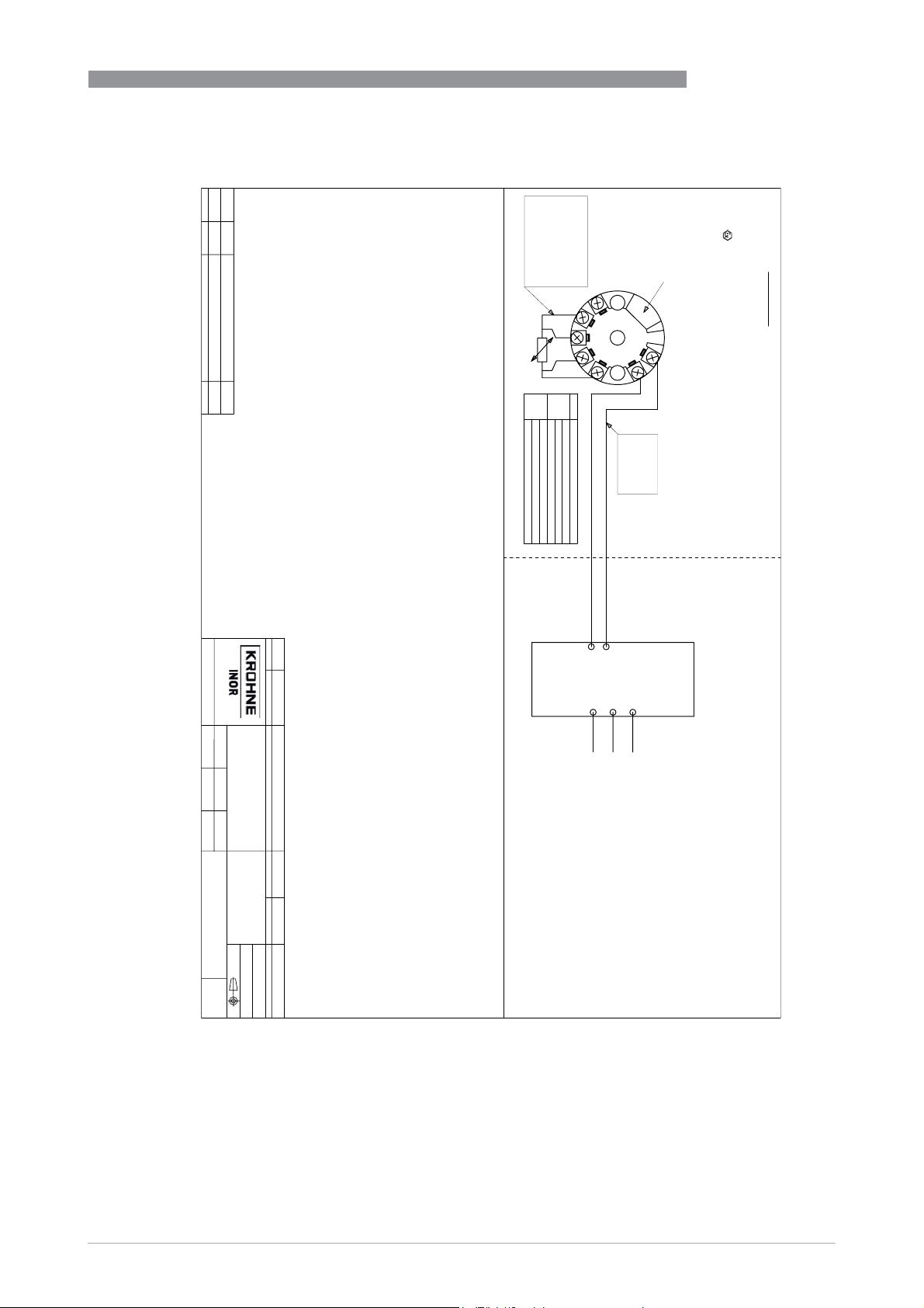
IPAQ C330/R330
Revision
Date
Comment
Approved by:
Rev 1
181030
First release revision
GP
Rev 2 190923
cFMus added, new values for Ta
GP
This drawing is property of Inor Process AB, Malmö, Sweden, without whose permission
it may not be copied, and the contents thereof must not be imparted to third party nor be
used for any unautherized purpose. Contravention will be prosecuted.
(RTD, T/C etc.)
IIA D 1000 1000
Sensor
T4: -40 °C (-40 °F) ≥ Ta ≥ +85 °C (+185 °F)
Po=19.1 mW
Uo=Voc=6.5 V
Io=Isc=11.7 mA
IIC A/B 24 400
IIB C 569 1000
Group Co=Ca Lo=La
(μF) (mH)
5
4
3
2
1
Power Pi
700 mW
900 mW
Temperature class: Temperature range
T6: -40 °C (-40 °F) ≥ Ta ≥ +55 °C (+131 °F)
T5: -40 °C (-40 °F) ≥ Ta ≥ +70 °C (+158 °F)
T4: -40 °C (-40 °F) ≥ Ta ≥ +85 °C (+185 °F)
T6: -40 °C (-40 °F) ≥ Ta ≥ +60 °C (+140 °F)
T5: -40 °C (-40 °F) ≥ Ta ≥ +75 °C (+167 °F)
APPENDIX
Europe:
KIWA 16ATEX0038 X
IECEx KIWA 16.0016X
CE 0539 II 1 G Ex ia IIC T6...T4 Ga
USB Connection
8
IPAQ C330X
+
6
-
7
Canada FM17CA0144X
Class I, Division 1, Groups A, B, C, D; T6...T4
Class I, Zone 0, Ex ia IIC T6...T4 Ga
Pi=Pmax=900 mW
Li=20μH
Ui=Vmax=30 V
Ii=Imax=100 mA
Ci = 23.1 nF
Class I, Zone 0, AEx ia IIC T6...T4 Ga
IS Class I, Division 1, Groups A, B, C, D; T6...T4
Hazardous (Classified) Location
North America:
USA FM17US0283X
File
4005488502dwg_2
SWEDEN
Designed by:
Date:
Installation and control drawing
IPAQ C330X
Temperature transmitter
2018-10-30
LH
Scale:
Approved by:
GP
1:1
No of sheets:
Sheet:
1
1
ZZ
Doc. type:
4005488502
Drawing number:
Projection:
General surface roughness Ra
Ra 3,2
Rev:
2
SS-ISO-2768-1 m
Title:
Treatment:
General tolerance
Det.no.
Quantity
Description
ATEX, IECEx and cFMus
Material
Document-ID
Article no.
40054885021000488846
the Certification Body.
Ex-document, may not be revised without approval from
degree of protection of at least IP20.
Power supply / 4-20 mA
2-Wire loop
Non Hazardous Location (Safe area)
ENTITY PARAMETERS
Po ≥ 0.9 W
La=Lo Li + Lcable
Isc=Io ≥ 100 mA
Ca=Co Ci + Ccable
Um = 250 V
250 V rms or dc
North America:
a degree of protection of at least IP20.
Voc=Uo ≥ 30 V
use or generate over
connected must not
The control equipment
5. Do not connect any communication equipment to the communication port
6. The transmitter shall be mounted into a suitable enclosure that provides
of the transmitter unless area is known to be non-hazardous.
ground shall be less than 1 ohm.
Associated apparatus
4. If a safety barrier is used and the safety barrier requires an earth conection
then the resistance between the terminal on the safety barrier and the earth
Inductance = 0.66 μH/m
Capacitance = 200 pF/m
3. If the cable parameters are unknown, the following values may be
used as a guideline:
1. The associated apparatus or intrincically safe equipment shall be certified.
2. Safety barriers must be installed in accordance with the
manufacturers instructions.
Europe:
(-)
(+)
- The transmitter's communication port (USB connection) may only be connected to the
- For the applicable ambient temperature range, see the sketch.
- The transmitter shall be mounted into a suitable enclosure that provides a
hazardous area, a connected sensor may be located in the hazardous area.
When the ICON-X is connected, the temperature transmitter shall be outside of the
certified ICON-X communication interface.
Specific conditions of use:
6. Do not connect any communication equipment to the communication port
resistance between the terminal on the safety barrier and the earth
ground shall be less than 1 ohm.
of the transmitter unless area is known to be non-hazardous.
5. If the safety barrier requires an earth conection then the
Inductance = 0.66 μH/m (0.20μH/feet)
4. If the cable parameters are unknown, the following values shall be
used:
Capacitance = 200 pF/m (60pF/feet)
2. Safety barriers must be installed in accordance with the
3. Installation must be accordance with the National Electrical Code
manufacturers instructions.
equipment or simple apparatus shall be certified.
(NFPA 70, Article 500 to 510), Canadian Electrical Code (CEC)
Section 18 and ANSI/ISA-RP12.06.01
1. The configuration of the associated apparatus or intrincically safe
www.inor.com09/2020 - 4007317401 – MA IPAQ 330 R02 en
53
Page 54
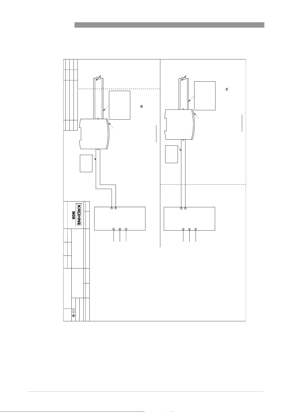
8
APPENDIX
Revision
Date
Comment
Approved by:
Rev 1
161123
First release revision
GP
Rev 2 170120
Changed value for Co
GP
Rev 3
180615
cFMus added, Co group IIA=1000 nF
GP
IPAQ C330/R330
This drawing is property of Inor Process AB, Malmö, Sweden, without whose permission
it may not be copied, and the contents thereof must not be imparted to third party nor be
used for any unautherized purpose. Contravention will be prosecuted.
Hazardous (Classified)
IECEx KIWA 16.0018X
CE 0539 II 1 G Ex ia IIC T6...T4 Ga
IS Class I, Division 1, Groups A, B, C, D; T4 to T6
Class I, Zone 0, AEx ia IIC Ga T4 to T6
Location
Europe:
KIWA 16ATEX0040 X
North America:
USA FM17US0283X
Non Hazardous Location (Safe area)
IPAQ R330X
(RTD, T/C etc.)
Sensor
Europe:
KIWA 16ATEX0040 X
IECEx KIWA 16.0018X
CE 0539 II 1 G Ex ia IIC T6...T4 Ga
T4: -40 °C ≥ Ta ≥ +85 °C
T5: -40 °C ≥ Ta ≥ +75 °C
T6: -40 °C ≥ Ta ≥ +60 °C
Po=405 mW
Uo=Voc=30 V
Io=Isc=54 mA
IIC A/B 38.1 11
IIB C 530 45
IIA D 1000 90
Group Co=Ca Lo=La
(nF) (mH)
1
2
3
4
USB Connection
Canada FM17CA0144X
Class I, Division 1, Groups A, B, C, D; T4 to T6
Class I, Zone 0, Ex ia IIC Ga T4 to T6
T4: -40 °C ≥ Ta ≥ +85 °C
T5: -40 °C ≥ Ta ≥ +75 °C
T6: -40 °C ≥ Ta ≥ +60 °C
21 +
22 -
Pi=Pmax=900 mW
Li=20μH
Ui=Vmax=30 V
Ii=Imax:100 mA
Ci = 23.1 nF
-40 °F ≥ Ta ≥ +185 °F
-40 °F ≥ Ta ≥ +167 °F
-40 °F ≥ Ta ≥ +140 °F
IS Class I, Division 1, Groups A, B, C, D; T4 to T6
Class I, Zone 0, AEx ia IIC Ga T4 to T6
Hazardous (Classified) Location
North America:
USA FM17US0283X
IPAQ R330X
(RTD, T/C etc.)
Sensor
Po=405 mW
Uo=Voc=30 V
Io=Isc=54 mA
IIC A/B 38.1 11
IIB C 530 45
IIA D 1000 90
Group Co=Ca Lo=La
(nF) (mH)
1
2
3
4
USB Connection
21 +
22 -
Pi=Pmax=900 mW
Li=20μH
Ui=Vmax=30 V
Ii=Imax:100 mA
Ci = 23.1 nF
T5: -40 °C ≥ Ta ≥ +75 °C
T6: -40 °C ≥ Ta ≥ +60 °C
-40 °F ≥ Ta ≥ +167 °F
-40 °F ≥ Ta ≥ +140 °F
T4: -40 °C ≥ Ta ≥ +85 °C
T5: -40 °C ≥ Ta ≥ +75 °C
T6: -40 °C ≥ Ta ≥ +60 °C
Canada FM17CA0144X
Class I, Division 1, Groups A, B, C, D; T4 to T6
Class I, Zone 0, Ex ia IIC Ga T4 to T6
T4: -40 °C ≥ Ta ≥ +85 °C
-40 °F ≥ Ta ≥ +185 °F
File
4005499601_3.dwg
SWEDEN
Designed by:
Date:
Installation and control drawing
IPAQ R330X
Temperature transmitter
2016-11-23
LH
Scale:
Approved by:
GP
1:1
No of sheets:
Sheet:
1
1
ZZ
Doc. type:
4005499601 3
Drawing number:
Projection:
General surface roughness Ra
Ra 3,2
Rev:
SS-ISO-2768-1 m
Title:
Treatment:
General tolerance
Det.no.
Quantity
Description
ATEX, IECEx and cFMus
Material
Document-ID
1000375907 4005499601
Article no.
the Certification Body.
Ex-document, may not be revised without approval from
provides a degree of protection of at least IP20.
Power supply / 4-20 mA
2-Wire loop
Power supply / 4-20 mA
2-Wire loop
Non Hazardous Location (Safe area)
ENTITY PARAMETERS
Po ≥ 0.9 W
La=Lo Li + Lcable
Isc=Io ≥ 100 mA
Ca=Co Ci + Ccable
Voc=Uo ≥ 30 V
250 V rms or dc
use or generate over
Specific conditions of use:
connected must not
The control equipment
Associated apparatus
6. Do not connect any communication equipment to the communication port
of the transmitter unless area is known to be non-hazardous.
resistance between the terminal on the safety barrier and the earth
ground shall be less than 1 ohm.
5. If the safety barrier requires an earth conection then the
Inductance = 0.66 μH/m (0.20μH/feet)
Capacitance = 200 pF/m (60pF/feet)
used:
4. If the cable parameters are unknown, the following values shall be
(-)
(+)
Um = 250 V
- The transmitter's communication port (USB connection) may only be
- For the applicable ambient temperature range, see the sketch.
- The transmitter shall be mounted into a suitable enclosure that
located in the hazardous area.
be outside of the hazardous area, a connected sensor may be
connected to the certified ICON-X communication interface.
When the ICON-X is connected, the temperature transmitter shall
(-)
2. Safety barriers must be installed in accordance with the
3. Installation must be accordance with the National Electrical Code
manufacturers instructions.
equipment or simple apparatus shall be approved.
(NFPA 70, Article 500 to 510), Canadian Electrical Code (CEC)
Section 18 and ANSI/ISA-RP12.06.01
(+)
1. The configuration of the associated apparatus or intrincically safe
North America:
5. Do not connect any communication equipment to the communication port
of the transmitter unless area is known to be non-hazardous.
then the resistance between the terminal on the safety barrier and the earth
ground shall be less than 1 ohm.
Um = 250 V
4. If a safety barrier is used and the safety barrier requires an earth conection
La=Lo Li + Lcable
250 V rms or dc
Inductance = 0.66 μH/m
Ca=Co Ci + Ccable
Po ≥ 0.9 W
use or generate over
Capacitance = 200 pF/m
Isc=Io ≥ 100 mA
Voc=Uo ≥ 30 V
connected must not
The control equipment
3. If the cable parameters are unknown, the following values may be
used as a guideline:
ENTITY PARAMETERS
Associated apparatus
1. The associated apparatus or intrincically safe equipment shall be approved.
2. Safety barriers must be installed in accordance with the
manufacturers instructions.
Europe:
54
www.inor.com
09/2020 - 4007317401 – MA IPAQ 330 R02 en
Page 55
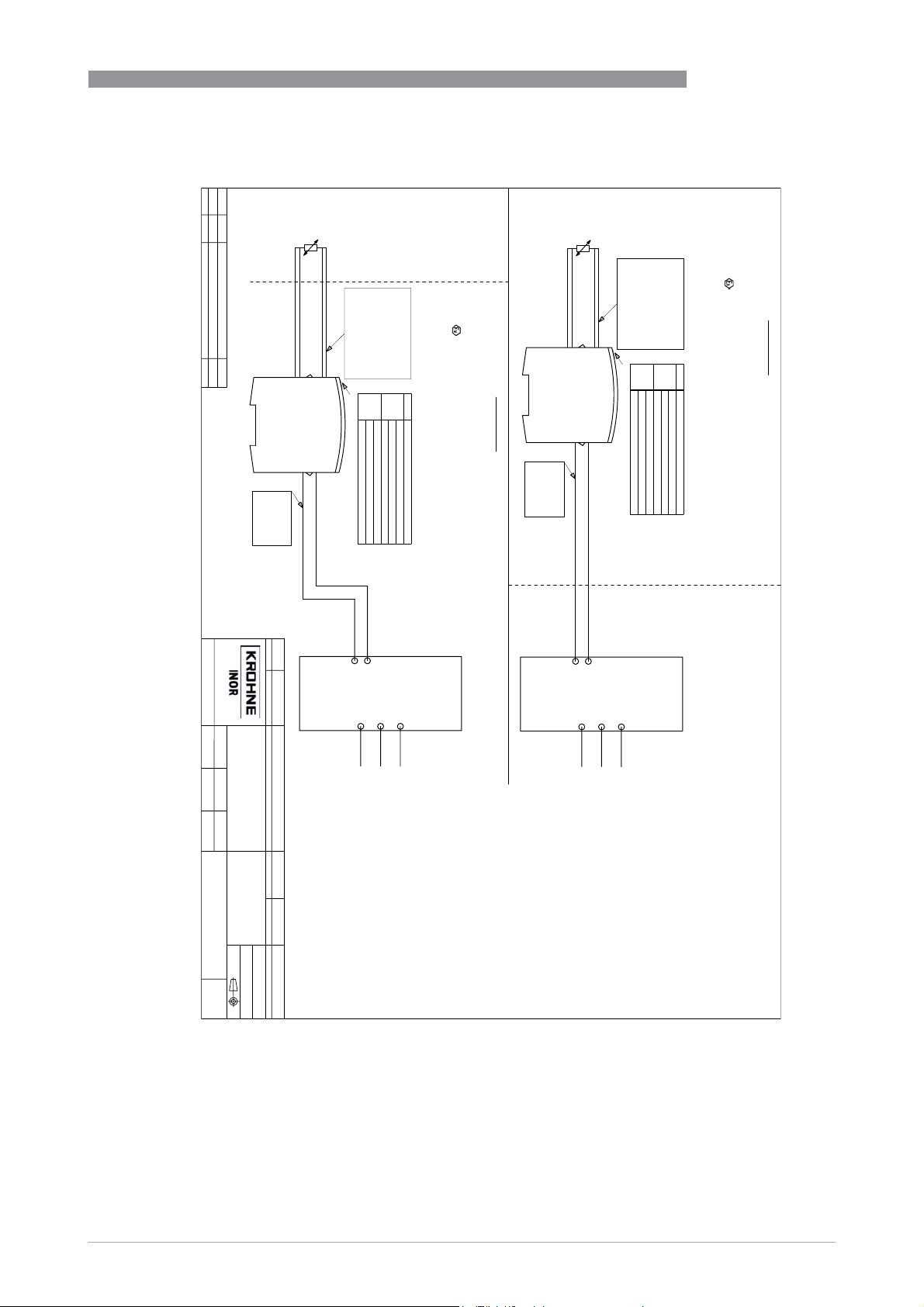
IPAQ C330/R330
Revision
Date
Comment
Approved by:
Rev 1
181030
First release revision
GP
Rev 2 190923
cFMus added, new values for Ta
GP
APPENDIX
This drawing is property of Inor Process AB, Malmö, Sweden, without whose permission
it may not be copied, and the contents thereof must not be imparted to third party nor be
used for any unautherized purpose. Contravention will be prosecuted.
Hazardous (Classified)
CE 0539 II 1 G Ex ia IIC T6...T4 Ga
Class I, Zone 0, AEx ia IIC T6...T4 Ga
IECEx KIWA 16.0018X
IS Class I, Division 1, Groups A, B, C, D; T6...T4
Location
Europe:
KIWA 16ATEX0040 X
IPAQ R330X
North America:
USA FM17US0283X
(RTD, T/C etc.)
Sensor
Europe:
KIWA 16ATEX0040 X
IECEx KIWA 16.0018X
IIA D 1000 1000
IIB C 569 1000
Po=19.1 mW
Uo=Voc=6.5 V
Io=Isc=11.7 mA
IIC A/B 24 400
Group Co=Ca Lo=La
(μF) (mH)
CE 0539 II 1 G Ex ia IIC T6...T4 Ga
IPAQ R330X
1
2
3
4
Power Pi
700 mW
USB Connection
900 mW
Temperature class: Temperature range
T6: -40 °C (-40 °F) ≥ Ta ≥ +55 °C (+131 °F)
T5: -40 °C (-40 °F) ≥ Ta ≥ +70 °C (+158 °F)
T4: -40 °C (-40 °F) ≥ Ta ≥ +85 °C (+185 °F)
T6: -40 °C (-40 °F) ≥ Ta ≥ +60 °C (+140 °F)
T5: -40 °C (-40 °F) ≥ Ta ≥ +75 °C (+167 °F)
T4: -40 °C (-40 °F) ≥ Ta ≥ +85 °C (+185 °F)
Hazardous (Classified) Location
North America:
USA FM17US0283X
IS Class I, Division 1, Groups A, B, C, D; T6...T4
Canada FM17CA0144X
Class I, Division 1, Groups A, B, C, D; T6...T4
Class I, Zone 0, Ex ia IIC T6...T4 Ga
Class I, Zone 0, AEx ia IIC T6...T4 Ga
21 +
22 -
Pi=Pmax=900 mW
Li=20μH
Ui=Vmax=30 V
Ii=Imax:100 mA
Ci = 23.1 nF
(RTD, T/C etc.)
Sensor
Po=19.1 mW
Uo=Voc=6.5 V
Io=Isc=11.7 mA
IIC A/B 24 400
IIB C 569 1000
IIA D 1000 1000
Group Co=Ca Lo=La
(μF) (mH)
1
2
3
4
Power Pi
700 mW
900 mW
USB Connection
Temperature class: Temperature range
T6: -40 °C (-40 °F) ≥ Ta ≥ +55 °C (+131 °F)
T5: -40 °C (-40 °F) ≥ Ta ≥ +70 °C (+158 °F)
T4: -40 °C (-40 °F) ≥ Ta ≥ +85 °C (+185 °F)
T6: -40 °C (-40 °F) ≥ Ta ≥ +60 °C (+140 °F)
T5: -40 °C (-40 °F) ≥ Ta ≥ +75 °C (+167 °F)
T4: -40 °C (-40 °F) ≥ Ta ≥ +85 °C (+185 °F)
Canada FM17CA0144X
Class I, Division 1, Groups A, B, C, D; T6...T4
21 +
22 -
Pi=Pmax=900 mW
Li=20μH
Ui=Vmax=30 V
Ii=Imax:100 mA
Ci = 23.1 nF
Class I, Zone 0, Ex ia IIC T6...T4 Ga
8
Non Hazardous Location (Safe area)
File
4005499602_2.dwg
SWEDEN
Date:
Designed by:
Installation and control drawing
IPAQ R330X
Temperature transmitter
2018-10-30
LH
Scale:
Approved by:
GP
1:1
No of sheets:
Sheet:
1
1
ZZ
Doc. type:
4005499602 2
Drawing number:
Projection:
General surface roughness Ra
Ra 3,2
Rev:
SS-ISO-2768-1 m
Title:
Treatment:
General tolerance
Det.no.
Quantity
Description
ATEX, IECEx and cFMus
Material
Document-ID
1000488861
Article no.
4005499602
the Certification Body.
Ex-document, may not be revised without approval from
provides a degree of protection of at least IP20.
Power supply / 4-20 mA
2-Wire loop
Power supply / 4-20 mA
2-Wire loop
Non Hazardous Location (Safe area)
ENTITY PARAMETERS
Po ≥ 0.9 W
La=Lo Li + Lcable
Isc=Io ≥ 100 mA
Ca=Co Ci + Ccable
Voc=Uo ≥ 30 V
250 V rms or dc
use or generate over
Specific conditions of use:
connected must not
The control equipment
Associated apparatus
6. Do not connect any communication equipment to the communication port
of the transmitter unless area is known to be non-hazardous.
resistance between the terminal on the safety barrier and the earth
ground shall be less than 1 ohm.
5. If the safety barrier requires an earth conection then the
Inductance = 0.66 μH/m (0.20μH/feet)
Capacitance = 200 pF/m (60pF/feet)
used:
4. If the cable parameters are unknown, the following values shall be
(-)
(+)
Um = 250 V
- The transmitter's communication port (USB connection) may only be
- For the applicable ambient temperature range, see the sketch.
- The transmitter shall be mounted into a suitable enclosure that
located in the hazardous area.
be outside of the hazardous area, a connected sensor may be
connected to the certified ICON-X communication interface.
When the ICON-X is connected, the temperature transmitter shall
(-)
2. Safety barriers must be installed in accordance with the
3. Installation must be accordance with the National Electrical Code
manufacturers instructions.
equipment or simple apparatus shall be certified.
(NFPA 70, Article 500 to 510), Canadian Electrical Code (CEC)
Section 18 and ANSI/ISA-RP12.06.01
(+)
1. The configuration of the associated apparatus or intrincically safe
North America:
5. Do not connect any communication equipment to the communication port
of the transmitter unless area is known to be non-hazardous.
then the resistance between the terminal on the safety barrier and the earth
ground shall be less than 1 ohm.
Um = 250 V
4. If a safety barrier is used and the safety barrier requires an earth conection
La=Lo Li + Lcable
250 V rms or dc
Inductance = 0.66 μH/m
Ca=Co Ci + Ccable
Po ≥ 0.9 W
use or generate over
Capacitance = 200 pF/m
Isc=Io ≥ 100 mA
Voc=Uo ≥ 30 V
connected must not
The control equipment
3. If the cable parameters are unknown, the following values may be
used as a guideline:
ENTITY PARAMETERS
Associated apparatus
1. The associated apparatus or intrincically safe equipment shall be certified.
2. Safety barriers must be installed in accordance with the
manufacturers instructions.
Europe:
www.inor.com09/2020 - 4007317401 – MA IPAQ 330 R02 en
55
Page 56

9
NOTES
IPAQ C330/R330
56
www.inor.com 09/2020 - 4007317401 – MA IPAQ 330 R02 en
Page 57

IPAQ C330/R330
NOTES
9
www.inor.com09/2020 - 4007317401 – MA IPAQ 330 R02 en
57
Page 58

9
NOTES
IPAQ C330/R330
58
www.inor.com 09/2020 - 4007317401 – MA IPAQ 330 R02 en
 Loading...