

Page 1
ISOLATION
AMPLIFIER
for mA / V Signals with
2-wire Transmitter Supply
MAIN FEATURES
DA561
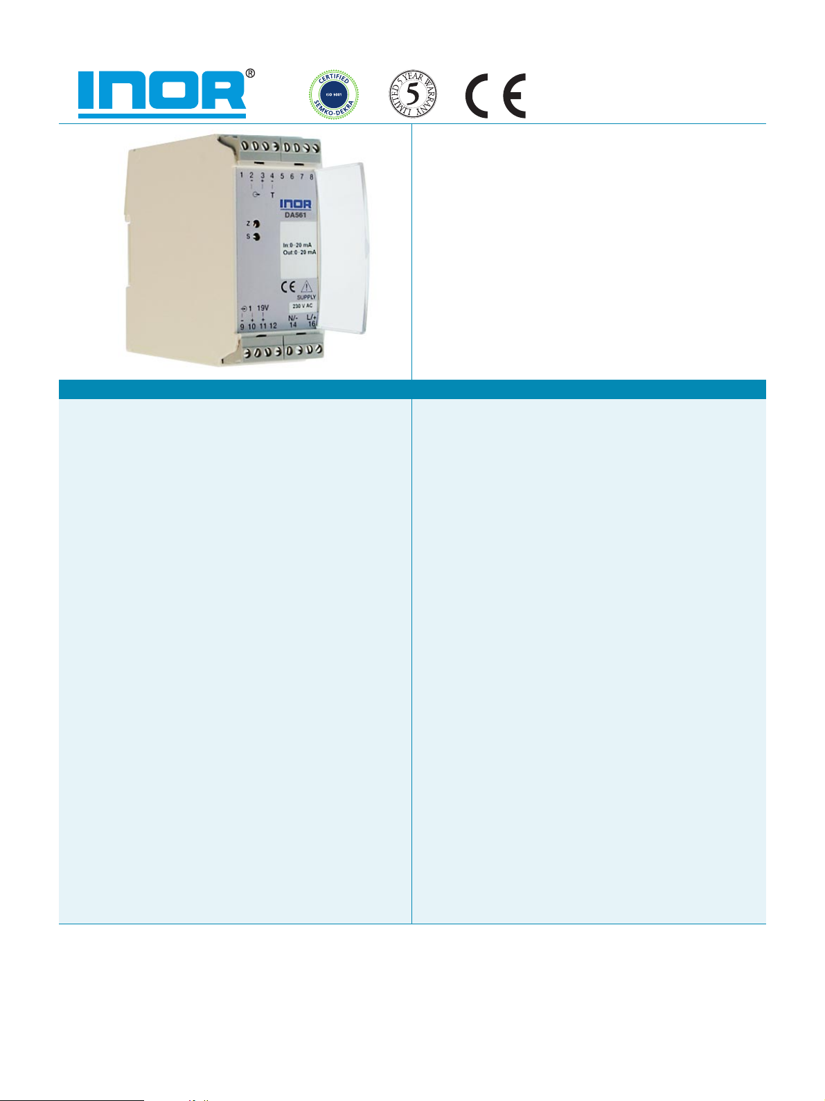
DA561 is specially designed for signal isola-
tion and load amplification in the process in-
dustry.
A 2-wire transmitter can be connected to and
supplied from the isolation amplifier.
DA561 maintains a high isolation level (1,5 kV)
between input and output.
Current and voltage can be chosen indepen-
dently as input and output signals.
Applications
- Voltage feed for a 2-wire transmitter, and galvanic isolation from
its mA circuits.
- Galvanic isolation, when a mA signal is connected, to more than
one measurement or monitoring system.
- Conversion of measurement range 0-20 mA to 4-20 mA or vice
versa.
- Load amplification and isolation when extra high load capacity
is needed.
2-wire transmitter supply
A 2-wire, 4-20 mA, transmitter can be connected directly to the
input of the DA561, thanks to the built-in transmitter supply.
Configuration flexibility
DA561 is designed for the most usual input and output process
signals, such as mA and V.
Input and output ranges are changed with the help of jumper
connections, and a simple instruction table.
Fine adjustment of the amplifiers zero point and span can be
made with potentiometers accessible from the front of the unit.
Noise immunity
DA561 meets the high demands from the process industry of good
EMC performance. Criterion A applies for all EMC tests, which
means that the amplifier stays within specifications during EMC
influence.
Test connections
The mA output signal can be measured on the front terminals
with a low-ohm mA instrument without breaking the output
circuit.
Plug-in, screw terminals
DA561 is connected via plug-in screw terminals. The terminal blocks
and cables are easy to disconnect from the unit for convenient
dismantling and service. Installation is simplified by connection
diagrams on the front panel.
Compact mounting on DIN-rail
DA561 snaps on to a 35 mm DIN-rail and can be mounted with
high density.
PO Box 9125, S-200 39 Malmö, Sweden, PHONE +46-40-31 25 60, FAX +46-40-31 25 70, E-MAIL [email protected] WEB www.inor.se
Rodenbacher Chaussee 6, Gebäude 805, D-63457 Hanau-Wolfgang, PHONE +49-6181-582940, FAX +49-6181-582944,
1860 Renaissance Blvd., Suite 203, Sturtevant, WI 53177,USA, PHONE +1-262-884-4535, FAX +1-262-884-4537, E-MAIL [email protected]
INOR PROCESS AB
INOR TRANSMITTER GmbH
E-MAIL [email protected]
INOR TRANSMITTER Inc.
www.inor.com
Page 2
SPECIFICATIONS D A 5 6 1
INPUT
Voltage 0(0.2)-1 V, 0(1)-5 V, 0(2)-10 V
Current 0(4)-20 mA (standard setting)
Maximum input level 200 % of measurement span
OUTPUT
Voltage
Current 0(4)-20 mA, open or short circuit protected (standard setting)
Response time T(50 %) Appr. 25 ms
Ripple Max. 50
TRANSMITTER SUPPLY
Supply voltage 19 VDC, max. ripple 100 mV p-p
ENVIRONMENT CONDITIONS
Ambient temperature Operation -20 to +60 °C
Humidity 0 to 95 %RH
EMC EN 50081-2, EN 50082-2 (Industrial) Criterion A (within specifications)
LVD IEC 1010-1 Installation category III, maximum 250 V
GENERAL DATA
Galvanic isolation AC & DC version
Power supply AC version 230 VAC, -15..+10 %, 45..75 Hz,
Power consumption 4 VA
ACCURACY
Calibration ±0.1 %
Linearity ±0.1 %
Repeatability ±0.05 %
Temperature influence ±0.15 %
Supply voltage influence ±0.05 %
Long-term stability First 3 months (burn-in) ±0.2 %
HOUSING
Weight Appr. 500 g
Protection IP 20
Connection Plug-in terminals Stranded, ≤ 2.5 mm
Mounting Rail acc. to DIN EN 50022, 35 mm
1)
Of input span
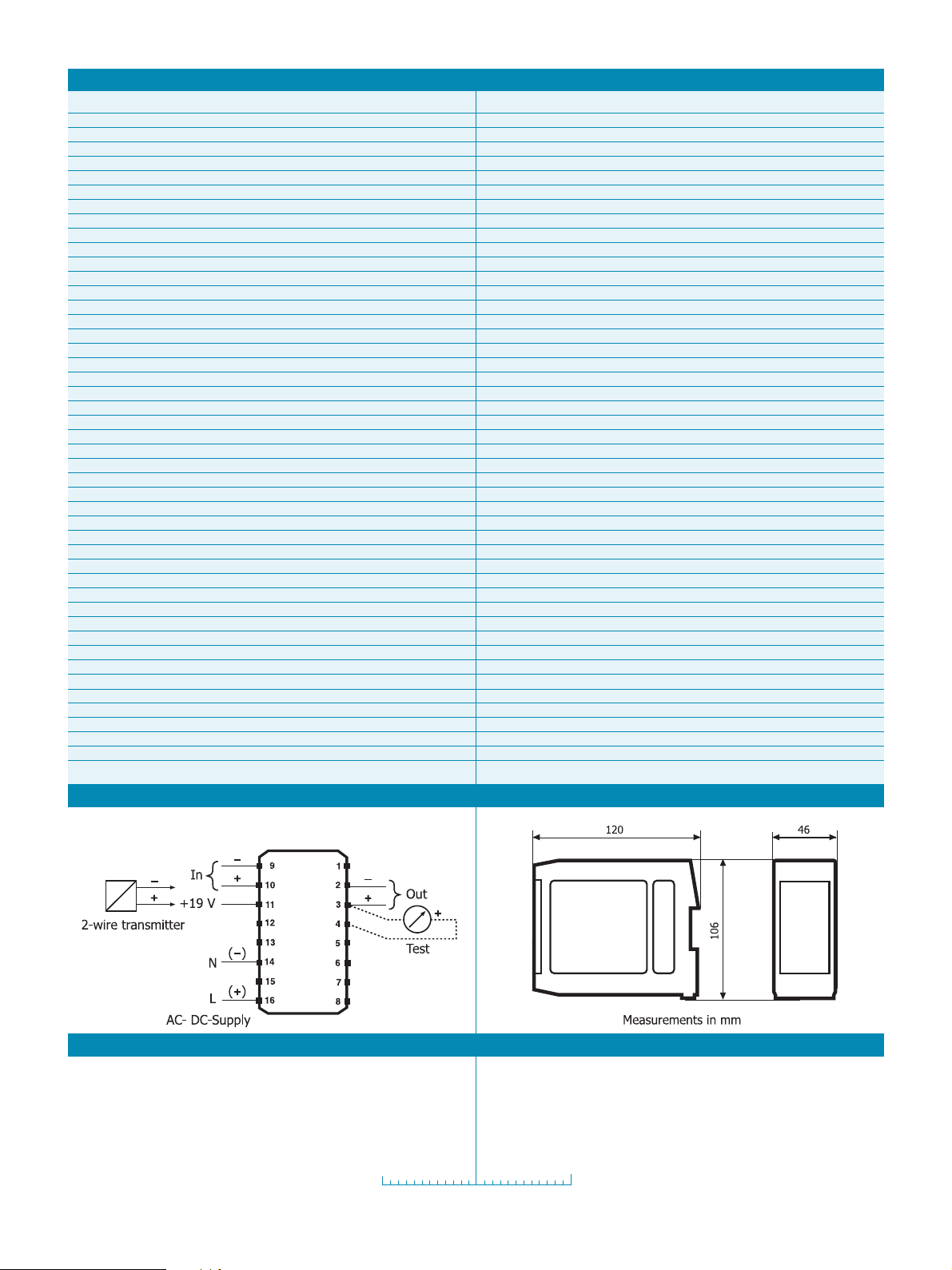
CONNECTIONS
Input impedance 1 Mohm
Input impedance 11.9 ohm
0(0.2)-1 V, 0(1)-5 V, 0(2)-10 V, short circuit protected
Minimum load 500 kohm (error effect <0.1 %)
Voltage limitation Appr. 56 V
Maximum load 600 ohm
Current limitation Appr. 23 mA
Test output mA instrument, Ri ≤ 10 ohm
T(90 %) Appr. 100 ms
µA, 5 kHz
Storage -25 to +70 °C
Input to output 1 500 VAC, 1 min
Input/output to power supply 2 200 VAC, 1 min
DC version 19 to 60 VDC
1)
1)
1)
1)
/ 10 °C
1)
within variation range
1)
/ year
After 3 months ±0.05 %
1)
/ year
2
, AWG 14
DIMENSIONS
DA561
ORDERING INFORMATION
DA561 230 VAC 51MOE00006
DA561 19-60 VDC 51MOE00007
Configuration
All information subject to change without notice.
70CAL00001
MEASURING MADE A LITTLE EASIER
DISTRIBUTION
86DDA00001 2001-07
 Loading...