

Page 1

© Copyright 2016
Innovience International BV
Al rights reserved. Whole or partial reproduction is not permitted
without the written authorization of the copyright owner.
User manual OptoXSTM
Wifi module OXS-W11-EU
V 1.0, December 2016
Confidential
1
User manual
OptoXS™ Wifi module
Innovience International BV
Confidential
Page 2

© Copyright 2016
Innovience International BV
Al rights reserved. Whole or partial reproduction is not permitted
without the written authorization of the copyright owner.
User manual OptoXSTM
Wifi module OXS-W11-EU
V 1.0, December 2016
Confidential
2
Trademarks
Innovience International, OptoXSTM and the Innovience logo are trademarks or registered
trademarks of Innovience International BV or its subsidiaries in The Netherlands or other
countries. All other company or product names mentioned herein are trademarks or
registered trademarks of their respective companies.
Patents
This product is protected under the claims of WO2015187017 A2 and WO2015187017 A3. A
limited implied use license is granted for the personal and non-commercial use of a
consumer to use the product (1) solely in connection with other OptoXS
TM
components such
as but not limited to an OptoXSTM Switch and/or other products (to be) developed, marketed,
offered for sale or sold either directly or indirectly by Innovience International BV, its
subsidiaries or authorized resellers and (2) in reasonable accordance with the information as
presented in this document and/or other documents related to the installation,
commissioning, use and maintenance of products including embedded software stored
therein as is being published by Innovience International BV or any of its subsidiaries.
Statement
Revision 1.0
© Innovience International BV 2016
Note: All the information contained in this manual was correct at the time of publication.
However, as our engineers are always updating and improving the product, your
device’s software may have a slightly different appearance or modified functionality
than presented in this manual.
The purpose of this product is to create a constant network connection for your devices. As
such, it does not have a standby mode or use a power management mode. If you wish to
power down this product, please simply unplug it from the power outlet.
Page 3

© Copyright 2016
Innovience International BV
Al rights reserved. Whole or partial reproduction is not permitted
without the written authorization of the copyright owner.
User manual OptoXSTM
Wifi module OXS-W11-EU
V 1.0, December 2016
Confidential
3
Contents
Chapter 1 Introduction 4
1.1 Product overview 4
1.2 Conventions 4
1.3 Main features 4
1.4 Appearance 5
1.4.1 The front panel 5
1.4.2 The rear panel 5
1.4.3 The side panels 5
1.4.4 Cautions 6
1.4.5 Repair 7
1.4.6 Disposing of the module 7
1.4.7 Other 7
Chapter 2 Hardware Installation 8
2.1 Before you begin 8
2.2 Basic requirements 8
2.3 Connecting the device 9
Chapter 3 Quick Installation Guide 10
3.1 Quick setup 10
3.2 Wireless 12
3.3 Wireless security 13
Chapter 4 Advanced mode 15
4.1 Wifi settings 16
4.2 Security 19
4.3 Mac filter 21
4.4 Interface settings 22
4.5 LAN 22
4.6 URL block 26
4.7 Virtual server 26
Chapter 5 Virtual server 27
5.1 ALG 27
Table 5.1 System requirements 27
Table 5.2 Technical specifications (OXS-11n-EU 28
Chapter 6 Recovery and update features 30
6.1 Backup/Flash firmware 30
Chapter 7 Troubleshooting guide 32
Page 4

© Copyright 2016
Innovience International BV
Al rights reserved. Whole or partial reproduction is not permitted
without the written authorization of the copyright owner.
User manual OptoXSTM
Wifi module OXS-W11-EU
V 1.0, December 2016
Confidential
4
Chapter 1 Introduction
1.1 Product overview
The OptoXSTM Wifi module is dedicated to home and office wireless network solutions. It
allows for greater range and mobility within your wireless network. Increased mobility and
the absence of cabling will be beneficial for your network.
With using IEEE 802.11n wireless technology, your device can transmit wireless data at the
rate of up to 300Mbps. With multiple protection measures, including SSID broadcast control
and wireless LAN 64/128/-bit WEP encryption, Wifi protected Access (WPA2- PSK, WPA- PSK.
This device leverages some 802.11n features to provide improved performance and coverage
compared to 802.11a/g devices and fully interoperates with 802.11n products if they are
Wifi certified, but it does not conform to all of the requirements in the IEEE specification and
is not classified as "n" in a Wifi certified program.
It supports an easy, web-based setup for installation and management. Even though you
may not be familiar with the access point, you can easily configure it with the help of this
guide. Before installing the OptoXSTM Wifi module, please look through this guide to get the
full information.
1.2 Conventions
Parameters provided in the pictures are just references for setting up the product, which
may differ from the actual situation. You can set the parameters according to your demand.
1.3 Main Features
• Wireless speed up to 300 Mbps
• Support access point, multi-SSID, client, repeater(universal repeater)and bridge with
AP modes
• SSID and VLAN support
• Flexible deployment with POF connector
• Supports web management
• Backward compatible with 802.11b/g products
Page 5
© Copyright 2016
Innovience International BV
Al rights reserved. Whole or partial reproduction is not permitted
without the written authorization of the copyright owner.
User manual OptoXSTM
Wifi module OXS-W11-EU
V 1.0, December 2016
Confidential
5
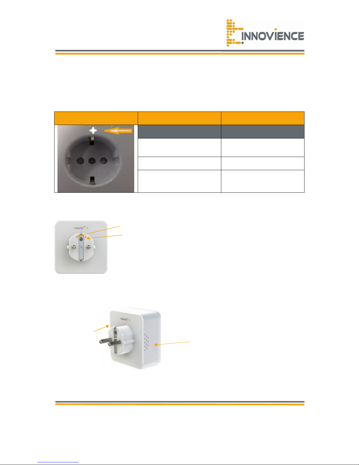
Tx/Rx optical inputs
Ventilation holes
DO NOT OBSTRUCT!
Reset button
1.4 Appearance
1.4.1 The Front Panel
The front panel of the OptoXSTM Wifi module consists of an LED indicator, which is designed
to indicate its condition. Viewed from left to right, the table bellow describes the LED on the
front panel of the device.
Name
Status
Indication
Off
The device is working
properly
On
The device is initializing
Flashing
The device has a system
error
1.4.2 The Rear Panel
1.4.3 The side panels
Reset
The reset button is used to restore the AP’s factory default settings. There are three ways to
reset the access point’s factory defaults:
Page 6

© Copyright 2016
Innovience International BV
Al rights reserved. Whole or partial reproduction is not permitted
without the written authorization of the copyright owner.
User manual OptoXSTM
Wifi module OXS-W11-EU
V 1.0, December 2016
Confidential
6
Method one
With the AP powered on, press and hold the reset button (about 5 seconds) until the system
LED becomes quick-flash. And then release the button and wait for the AP to reboot to its soft
default settings.
Method two
With the AP powered on, press and hold the reset button (about 10 seconds) until the system
LED becomes quick-flash. And then release the button and wait for the AP to reboot to its
factory default settings.
Method three
Restore the default settings from “System>Backup> Perform Reset” of the AP's web-
based management page.
Note: Ensure that the AP is powered on before it restarts completely.
1.4.4 Cautions
This Wifi module’s design and manufacturer has your safety in mind. In order to safely and
effectively use this Wifi module, please read the following before usage.
Usage cautions
The user should not open up nor modify this module in any way. Furthermore the ventilation
holes on either side of the module may not be obstructed. Otherwise the module may
overheat and become permanently damaged. The environmental temperature in which this
module may be used should be within +5 ~ +45 ℃.
Power
The router’s power voltage is 230Vac, 20mA.
This product only should be used in connection with Innovience International’s
OptoXSTM POF network solution. When using this product, please connect it only to a
(working!) power socket that has been prepared for the use of the OptoXSTM POF network
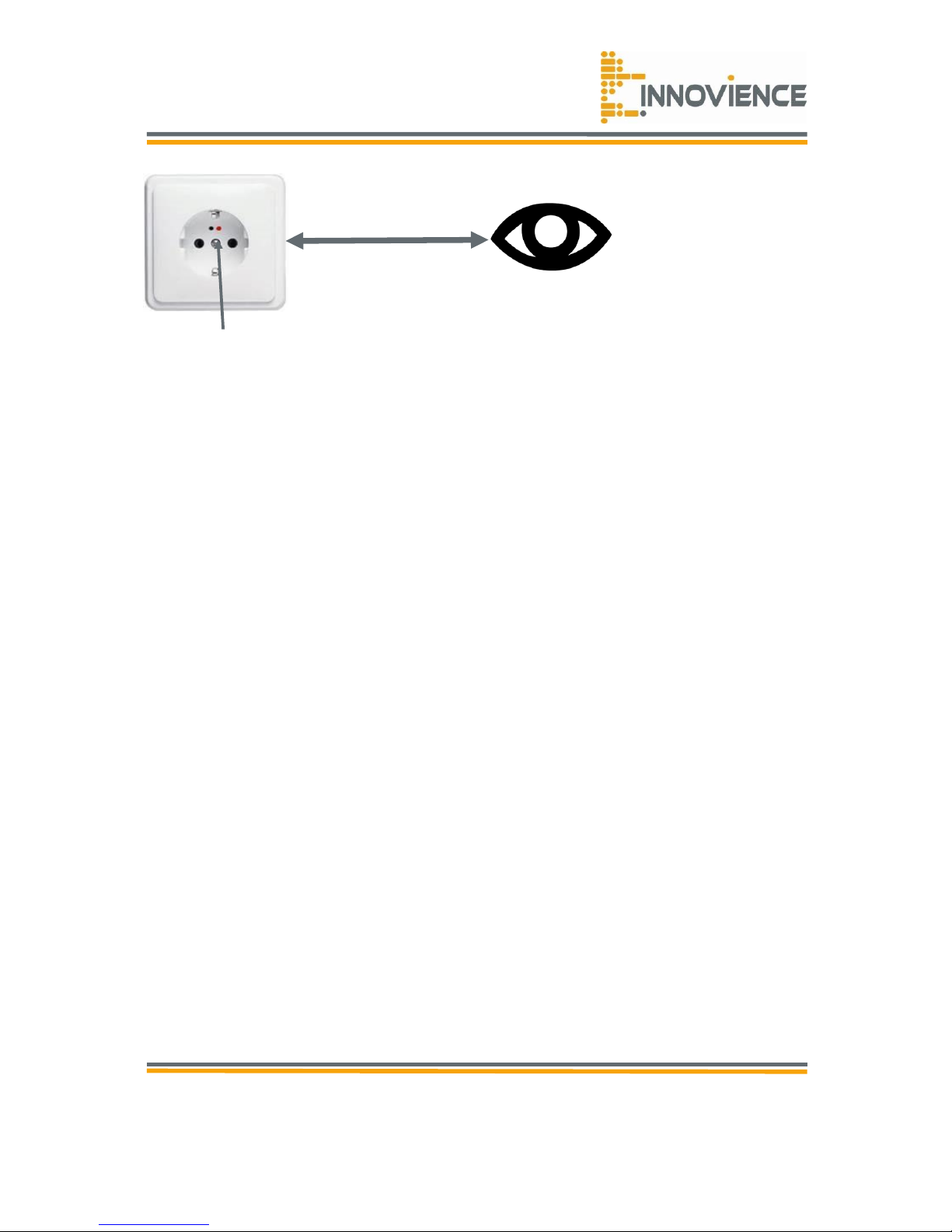
solution. I.e.: the target wall-socket is equipped with the two tiny holes at the top at which
a duplex POF cable is attached to. Before plugging the module into the OptoXSTM
prepared wall-socket, you should check wether there is red coloured light emitted
from the hole positioned at your right-hand-side. In the absence of a red coloured
light, you should check whether the OptoXS
TM
Switch is installed and running properly. When
placing the module into the targeted wall-socket, make sure it fits properly, cannot get
damaged or be subject to pressure. To reduce the risk of electric shock, unplug the module
first before cleaning it. Never connect the module to the targeted wall-socket in a humid or
dusty area.
Page 7
© Copyright 2016
Innovience International BV
Al rights reserved. Whole or partial reproduction is not permitted
without the written authorization of the copyright owner.
User manual OptoXSTM
Wifi module OXS-W11-EU
V 1.0, December 2016
Confidential
7
An active OptoXS
TM
enabled wall-socket will show a blinking red coloured light emerging from
the right hole.
1.4.5 Repair
If the OptoXSTM module encounters a malfunction or shows a problem within the
waranty period, you should send the module to your distributor. In any case you
should never attempt to open the module nor try to repair the module yourself. You
might damage the module or even endanger yourself.
1.4.6 Disposing of the module
When you would like to dispose your module, be sure to dispose it appropriately in
accordance with the rules of the local community in which you live. Some countries may
regulate disposal of an electrical device, so please consult with your local authority.
1.4.7 Other
When using this module, please do avoid that it comes into contact with water or other
liquids. If water is accidentally spilled on the module, you should NOT touch it while being
inserted in a powered wall socket. Instead you should remove the powerfuse and turn the
voltage down for that particular wall-socket, before you touch the module to remove it
permanently. After having unplugged the module, please use a dry cloth to absorb the
spillage and restore voltage. Electronic products are vulnerable, when using, please avoid
shaking or hitting the module and do not press the reset-button too hard.
Do not let the module come into contact with water or any other liquid. Do not disassemble,
repair or change the design of the module. Any damage done will not be included in the
repair policy. Avoid hitting the module with a hard object, avoid shaking the module and stay
away from magnetic fields. If during electrostatic discharge or a strong electromagnetic field
the product will malfunction, unplug it from the wall-socket. The product will return to
normal performance the next time it is plugged into a powered wall-socket.
>33cm (1.ft.)
Page 8

© Copyright 2016
Innovience International BV
Al rights reserved. Whole or partial reproduction is not permitted
without the written authorization of the copyright owner.
User manual OptoXSTM
Wifi module OXS-W11-EU
V 1.0, December 2016
Confidential
8
Chapter 2 Hardware Installation
2.1 Before you begin
Please read this User guide carefully before installing and using the equipment. The
operating distance range of your wireless connection can vary significantly depending on the
physical position of the wireless devices. Factors that can weaken signals by getting in the
way of your network’s radio waves are metal appliances or obstructions and walls. Typical
ranges vary based on the types of materials and background RF (Radio Frequency) noise in
your home or office.
For best performance of your wireless network, you are suggested to:
1. Avoid redundant obstacles and interference between the wireless devices.
2. Keep your AP away from appliances with a strong electric field or magnetic field, such
as a microwave oven or refrigerator. Place the AP near the center of the area in
which your wireless device operates.
2.2 Basic requirements
Place your AP in a well ventilated place far from direct sunlight, any heater or heating vent.
Leave at least 2 inches (5 cm) space around the device for heat dissipation.
Operating temperature: 0℃ ~ 40℃ (32℉ ~ 104℉)
Operating humidity: non-condensing
Page 9
© Copyright 2016
Innovience International BV
Al rights reserved. Whole or partial reproduction is not permitted
without the written authorization of the copyright owner.
User manual OptoXSTM
Wifi module OXS-W11-EU
V 1.0, December 2016
Confidential
9
2.3 Connecting the device
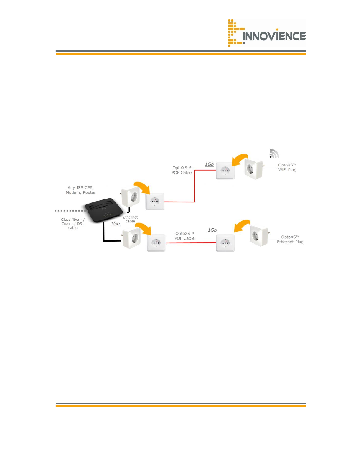
Figure 2.1 is an example of the typical application of an OptoXSTM Wifi module in the
infrastructure network. An OptoXSTM infrastructure network contains a (ISP)router, OptoXSTM
Ethernet module, a POF network cable and a modified power socket.
Atttention: Be sure the indicator light is positioned on the right sight, seen from the
powerholes beneath them.
Figure 2.1
Page 10
© Copyright 2016
Innovience International BV
Al rights reserved. Whole or partial reproduction is not permitted
without the written authorization of the copyright owner.
User manual OptoXSTM
Wifi module OXS-W11-EU
V 1.0, December 2016
Confidential
10
Chapter 3 Quick installation guide
This chapter will guide you to configure your PC to communicate with the AP and to
configure and manage the OptoXSTM Wifi module easily with a web-based utility.
3.1 Quick setup
With a web-based utility, it is easy to configure and manage the OptoXSTM Wifi module. The
web-based utility can be used on any Windows, Macintosh or UNIX OS with a web browser,
such as Microsoft Internet Explorer, Mozilla Firefox or Apple Safari.
Note: If you cannot access the web-based configuration page, you can choose the two
methods listed below based on your need. To reconfigure the OptoXSTM Wifi module
please refer to T1 in Troubleshooting to reset the product. To change only some
certain settings of the OptoXSTM Wifi module, please refer to T3 in Troubleshooting to
search IP address for your OptoXSTM Wifi module.
Method 1
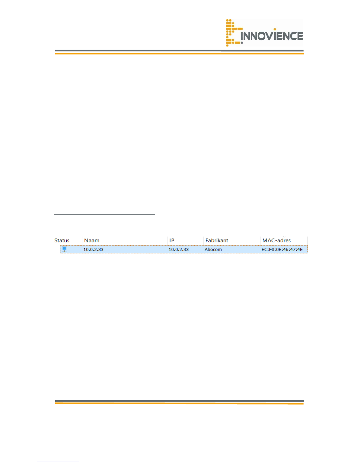
To access the configuration utility, you will have to find the device’s IP adress. In this guide
we use software ‘Advanced IP Scanner’. Advanced IP Scanner will show a result as shown in
figure 3.1. This free software can be downloaded from:
http://www.advanced-ip-scanner.com.
Figure 3.1
Page 11
© Copyright 2016
Innovience International BV
Al rights reserved. Whole or partial reproduction is not permitted
without the written authorization of the copyright owner.
User manual OptoXSTM
Wifi module OXS-W11-EU
V 1.0, December 2016
Confidential
11
Method 2
In the current case the OptoXSTM Wifi module has been assigned a IPv4 address “10.0.2.33”.
Now that we know the module’s IP address, we can continue to the Login procedure. To
access the configuration utility, open a web-browser and type in the default address in the
address field of the browser.
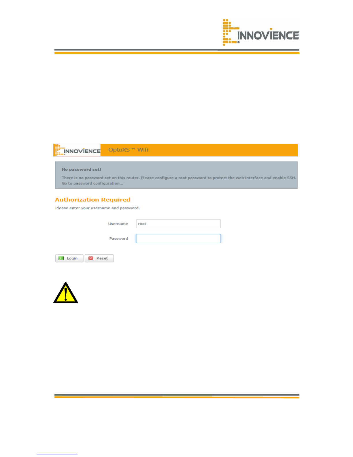
After a moment, a login window will appear, similar to figure 3.2.
Figure 3.2
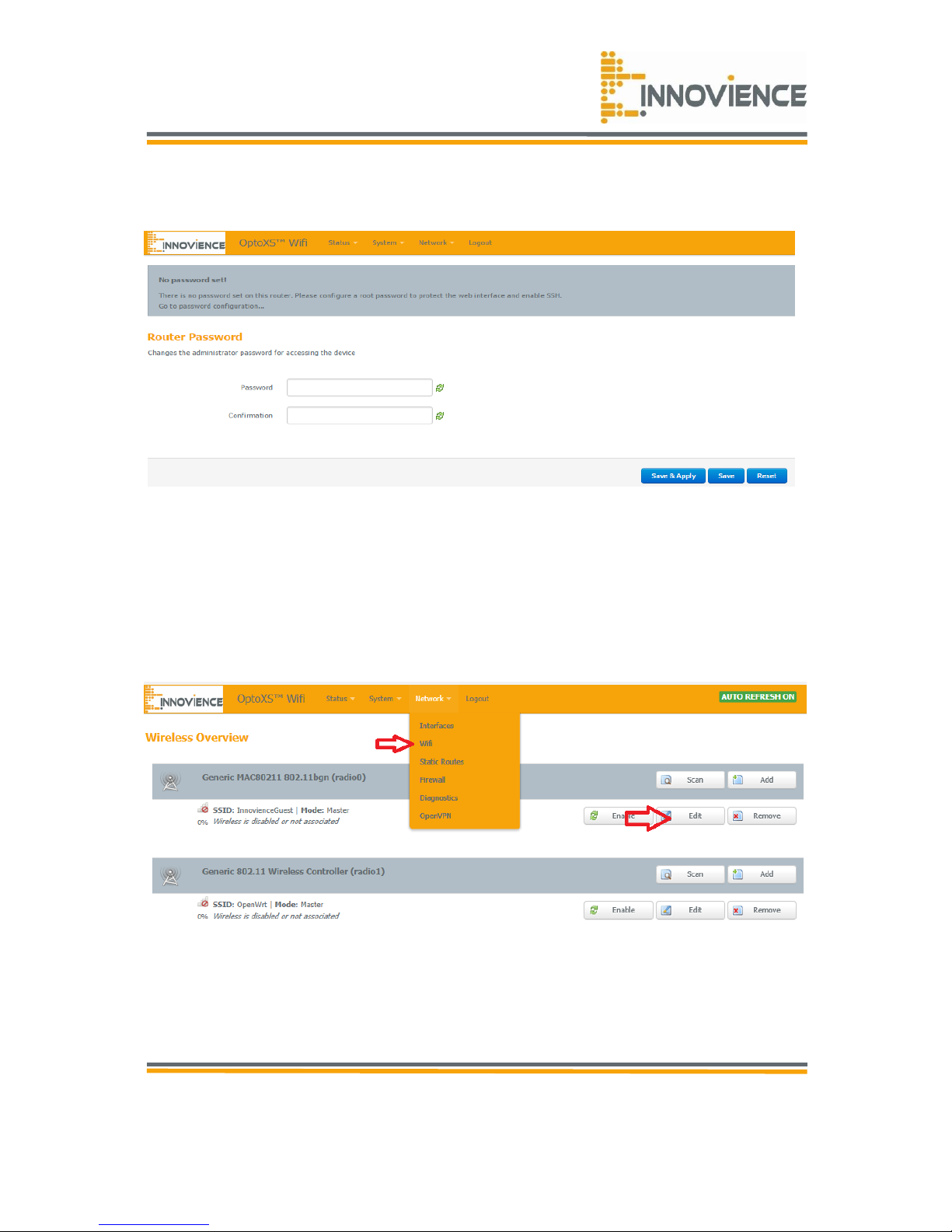
You should configure a password for your module. Go to the grey block above and navigate
to the last sentence “Go to password configuration”. Click on that sentence. The following
screen appears:
Page 12
© Copyright 2016
Innovience International BV
Al rights reserved. Whole or partial reproduction is not permitted
without the written authorization of the copyright owner.
User manual OptoXSTM
Wifi module OXS-W11-EU
V 1.0, December 2016
Confidential
12
Figure 3.3
Type a desired password. Choose a rather strong one including capitals and symbols like “?’,
“!”, etc. Confirm the password and then click on “Save & Apply”.
3.2 Wireless
Welcome to the homepage of the Wifi module! Lets start with the making of a Wireless
network.
To open the Wifi configuration page you open under the tab ‘Network’ the option: Wifi. In
the Wireless overview which opens after the click is a block called ‘Radio0’. In that block you
can press the ‘Edit’ button.
Page 13
© Copyright 2016
Innovience International BV
Al rights reserved. Whole or partial reproduction is not permitted
without the written authorization of the copyright owner.
User manual OptoXSTM
Wifi module OXS-W11-EU
V 1.0, December 2016
Confidential
13
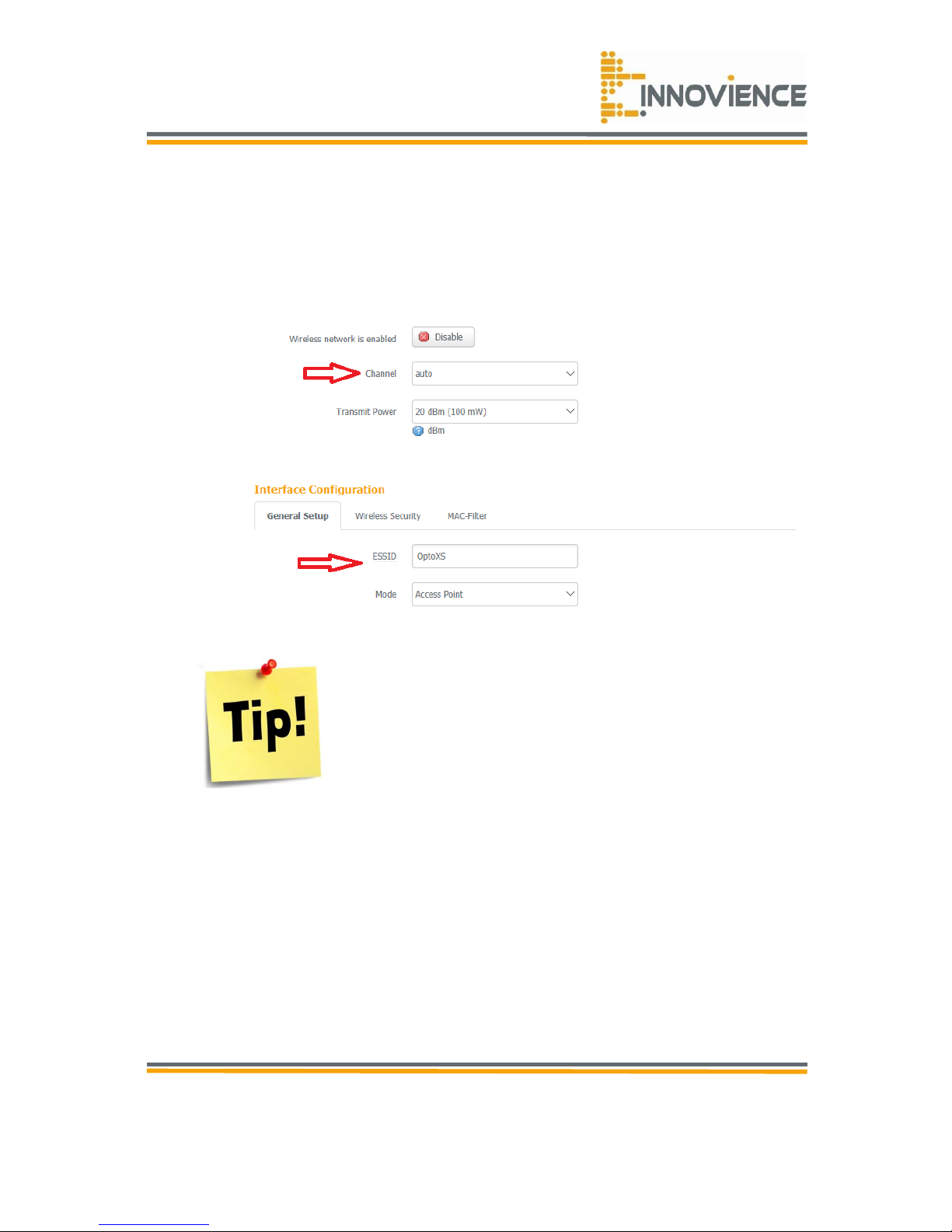
3.3 Wireless setting
Now you should create an easy-to-remember name for your wireless network, write it into
Wireless Network Name(SSID).
• Select the channel for your device. More information on channel configuration can be
found further on in the manual.
When you are using multible OptoXSTM Wifi units please use an
array of the channels 1, 6 and 11. These channels do not overlay
each other and therefor provide maximum coverage of your
network.
Wireless security
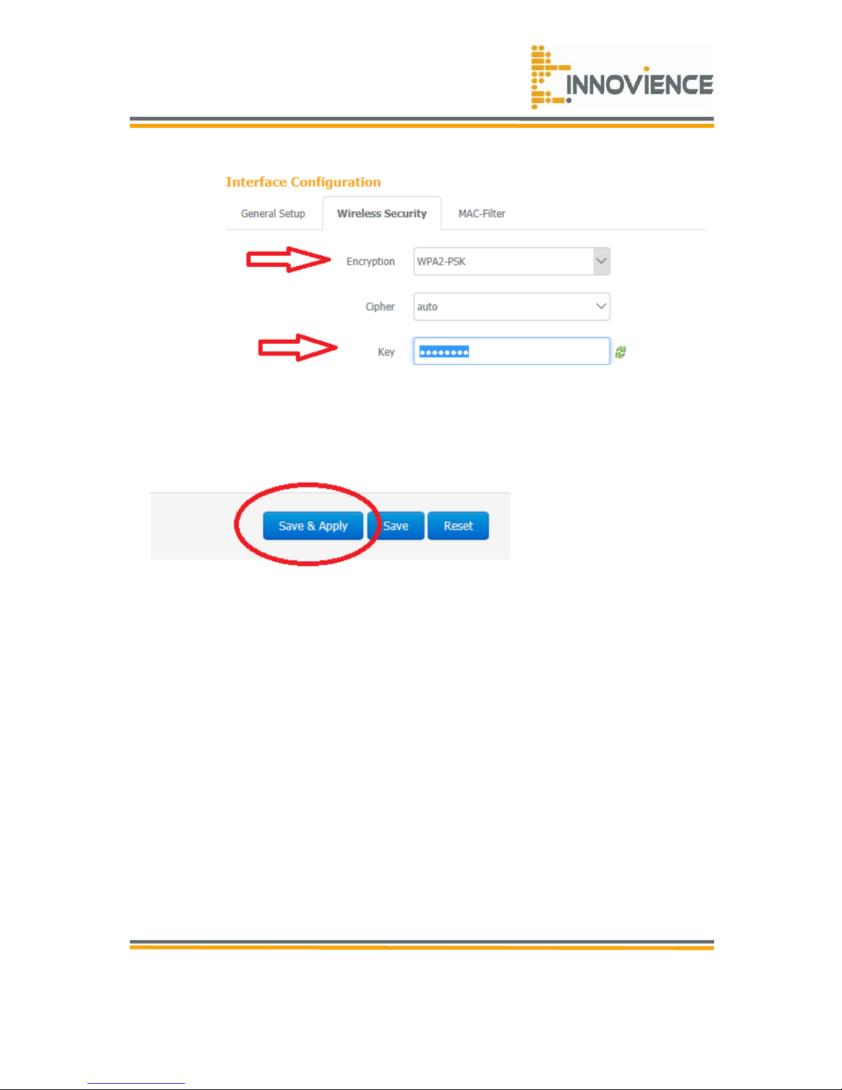
1. Next click on the tab ‘Wireless Security’, you will then go to the security page.
2. Select Most Secure (WPA/WPA2-PSK) encryption mode and enter a (8 digit) password
below to prevent unauthorized access to your AP. Due to safety reasons we advice
you to use the WPA2-PSK encryption.
Page 14
© Copyright 2016
Innovience International BV
Al rights reserved. Whole or partial reproduction is not permitted
without the written authorization of the copyright owner.
User manual OptoXSTM
Wifi module OXS-W11-EU
V 1.0, December 2016
Confidential
14
3. Now click ‘Save and Apply’ to set all the previously given input as an default.
Congratulations! You should have a working Opto STM Wifi network from this
point on.
Page 15
© Copyright 2016
Innovience International BV
Al rights reserved. Whole or partial reproduction is not permitted
without the written authorization of the copyright owner.
User manual OptoXSTM
Wifi module OXS-W11-EU
V 1.0, December 2016
Confidential
15
Chapter 4 Advanced mode
In advanced mode we will go through every possible setting so you can enjoy the maximum
performance of the OptoXSTM Wifi module!
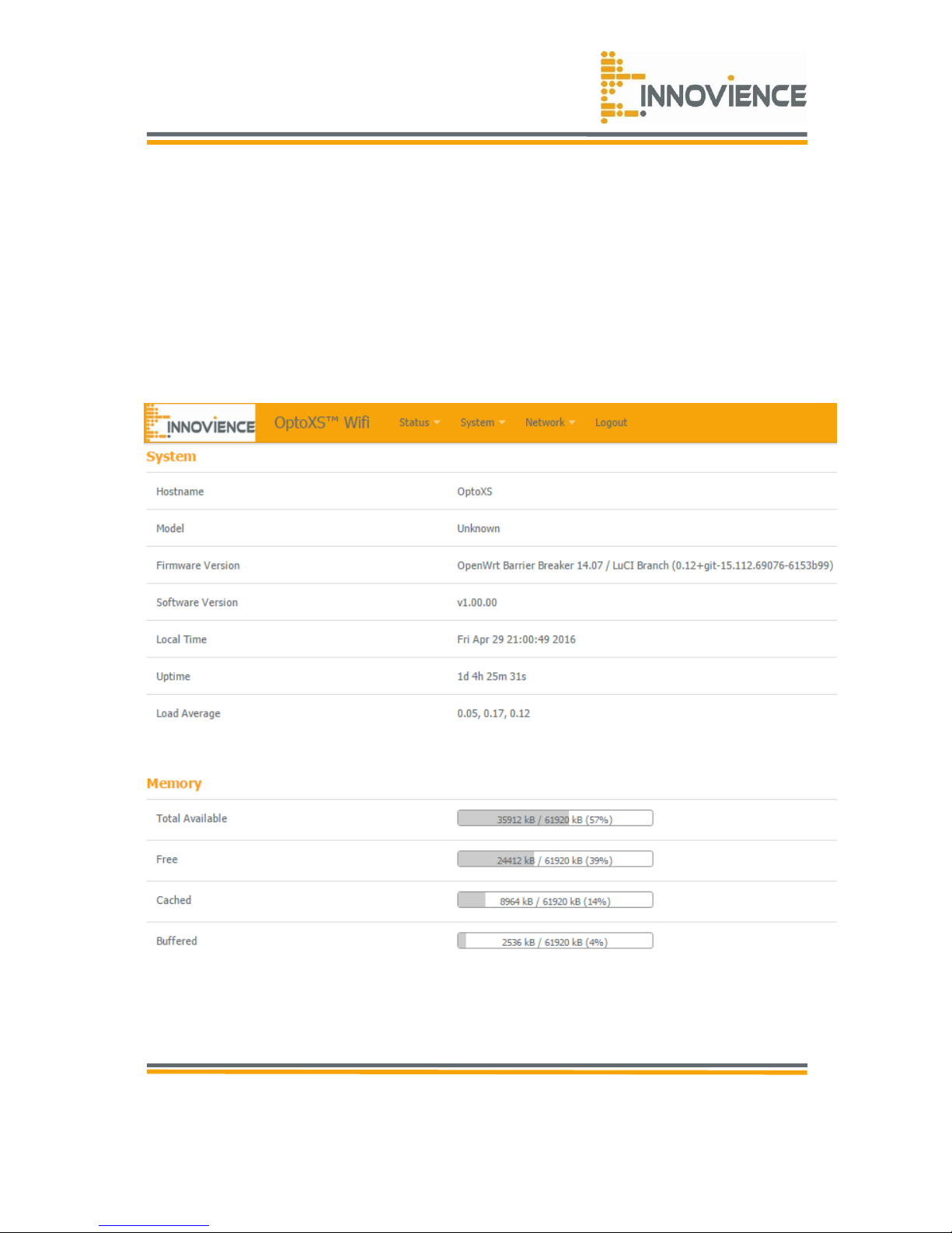
We start at the main page as shown in figure 4.0 bellow.
Figure 4.0
Page 16
© Copyright 2016
Innovience International BV
Al rights reserved. Whole or partial reproduction is not permitted
without the written authorization of the copyright owner.
User manual OptoXSTM
Wifi module OXS-W11-EU
V 1.0, December 2016
Confidential
16
4.1 Wifi settings
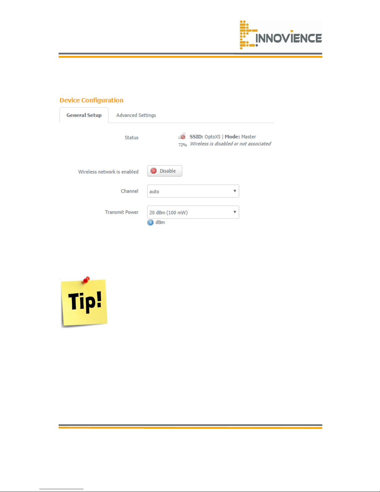
Figure 4.1
• Channel: the channel used by the wireless LAN. All devices in the same wireless LAN
should use a different channel. We advice a ratio of 5 points so you should use a
combination of channel 1, 6 or 11. If you are not sure which channel is best to use, then
keep the value of “auto”.
Use Wifi-Info-View to determine which channel is available for usage.
You can download the free utility on the website:
http://www.nirsoft.net/utils/wifi_information_view.html
• Transmit power: the transmit power can be set to a bare minimum (1mW) or maximum
power (100mW) for better performance. (As from 2018 the maximum outlet level in
Europe is set to 30 Mw)
Page 17
© Copyright 2016
Innovience International BV
Al rights reserved. Whole or partial reproduction is not permitted
without the written authorization of the copyright owner.
User manual OptoXSTM
Wifi module OXS-W11-EU
V 1.0, December 2016
Confidential
17
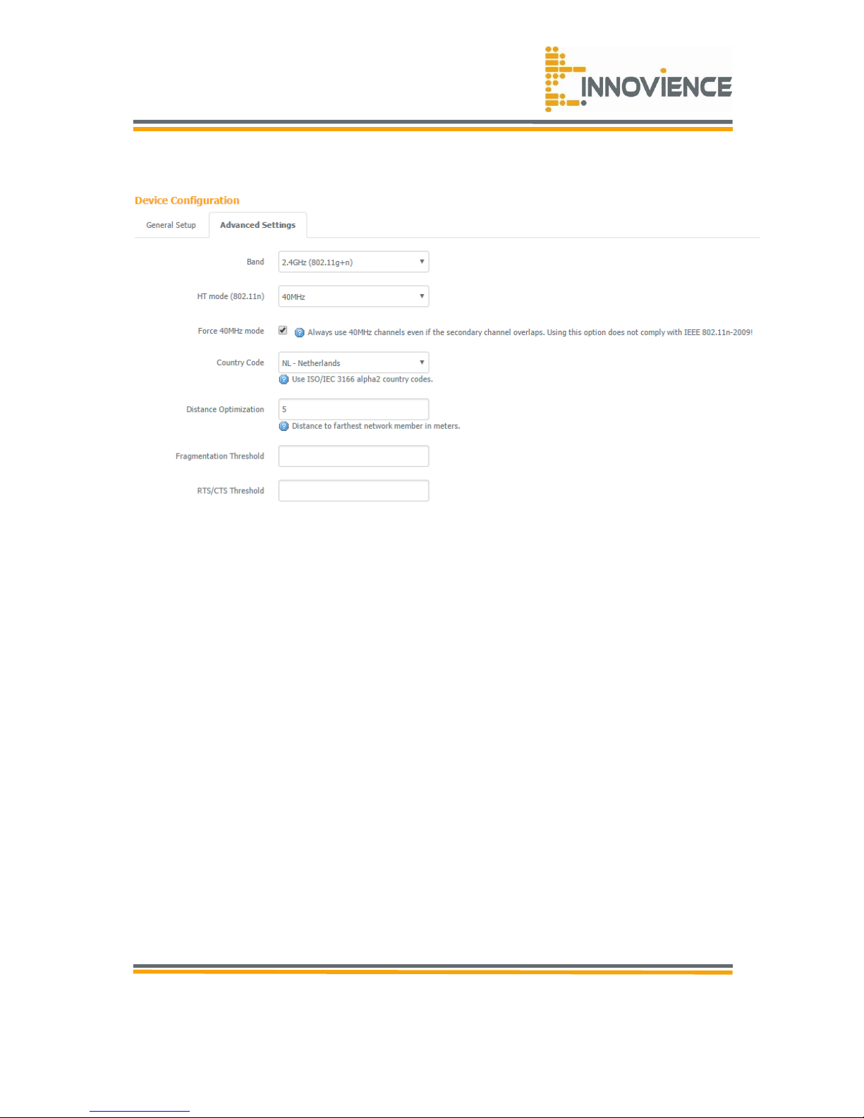
Figure 4.1.2
• Band: you only are able to choose 2.4GHz (802g+n) band since it is a single-band
module according to the “N-standard”.
• HT Mode: allows you to specify whether the AP should transmit on 20MHz or 40MHz
bandwidth.
• Force 40MHz mode: for maximum speed you should enable this mode. Modern devices
all are compatible with this mode. However, if you do own an older device that does not
function well, you should disable it to guarantee maximum device compatibility. Always
use 20Mhz when you use multiple OptoXSTM Wifi units for an optimal channel array.
• Data rate: this is the rate this access point uses to transmit data packets. The access
point will use the highest possible selected transmission rate to transmit the data
packets.
• Fragmentation threshold: this feature specifies the maximum size of a packet during the
fragmentation of data to be transmitted. If you set this value too low, it will result in bad
performance.
• RTS threshold: when the packet size is smaller than the RTS threshold, the wireless
router will not use the RTS/CTS mechanism to send this packet.
• CTS protection: clear to send (CTS) protection mode is a wireless setting that ensures
clients on a network can connect to an AP when many communication devices are
present.
Page 18
© Copyright 2016
Innovience International BV
Al rights reserved. Whole or partial reproduction is not permitted
without the written authorization of the copyright owner.
User manual OptoXSTM
Wifi module OXS-W11-EU
V 1.0, December 2016
Confidential
18
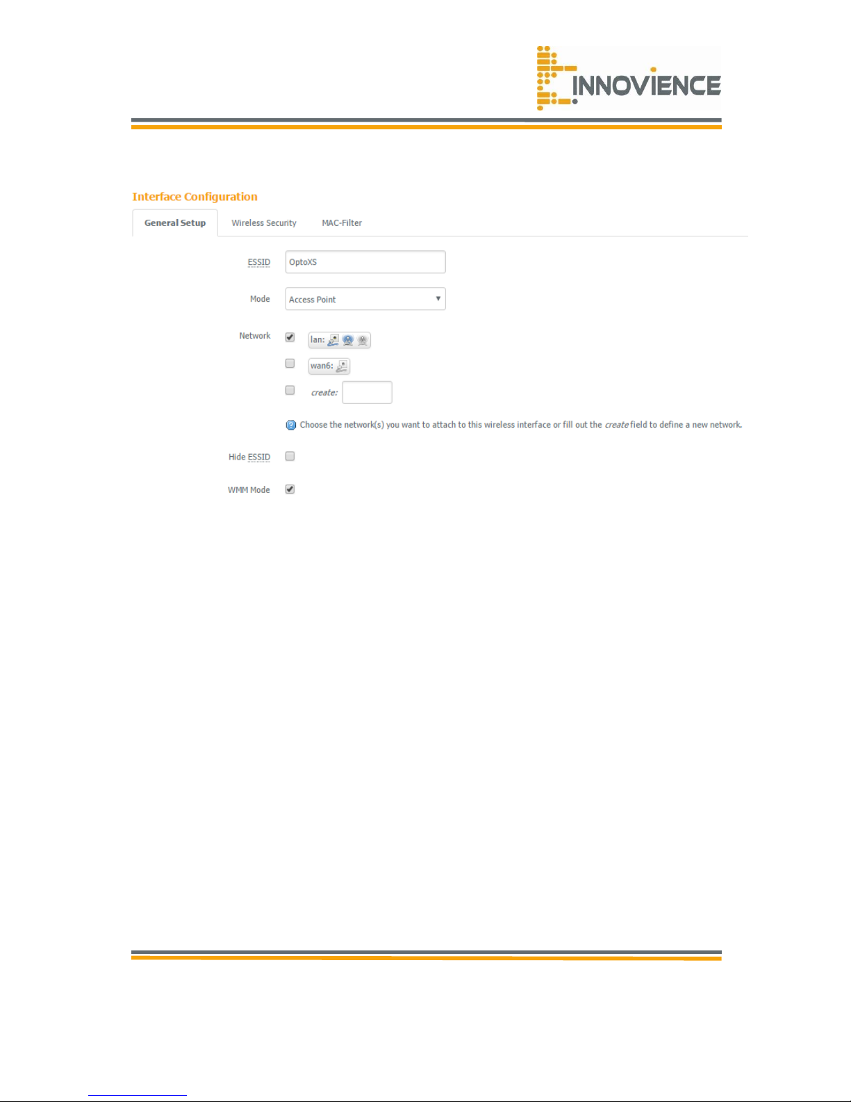
Figure 4.1.3 Interface configuration
• ESSID: this is the name of the wireless signal which is broadcasted. All the devices in the
same wireless LAN should have the same SSID.
• Mode: allows you to set the module in Access point Mode, client mode, etc. For un-
experienced users it is adviced to keep the module operating in Access point Mode.
• Hide ESSID: hides the network name (SSID) from being broadcasted publicly.
• WMM mode: this enables the Wifi multimedia network QoS feature. This prioritizes the
traffic of multimedia related data such as voice and video above other data/content on
your network.
Page 19
© Copyright 2016
Innovience International BV
Al rights reserved. Whole or partial reproduction is not permitted
without the written authorization of the copyright owner.
User manual OptoXSTM
Wifi module OXS-W11-EU
V 1.0, December 2016
Confidential
19
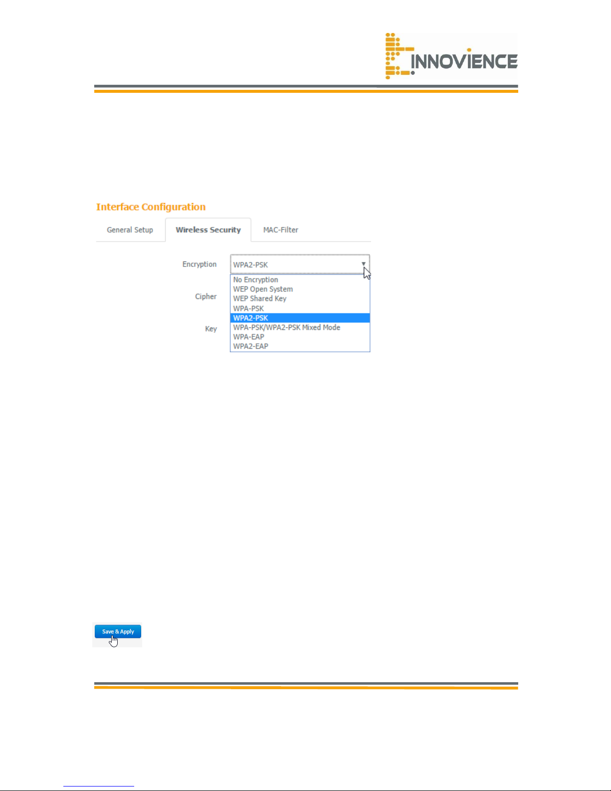
4.2 Security
This module provides complete wireless LAN security functions, included are WEP, IEEE
802.11x, and can prevent your wireless LAN from illegal access. Please make sure your
wireless stations use the same security function and are setup with the same security key.
Figure 4.2.1
No encryption
When you choose to disable encryption, this will create an open network. It is commonly
used in guest networks.
WEP
When you select a 64-bit or 128-bit WEP key, you have to enter WEP keys to encrypt data.
You can generate the key by yourself and enter it. You can enter four WEP keys and select
one of them as a default key. Then the router can receive any packets encrypted by one of
the four keys.
• Input Type: you may select ASCII characters (alphanumeric format) or Hexadecimal
digits (in the "A-F", "a-f" and "0-9" range) to be the WEP Key.
• Key length: you can select the WEP key length for encryption, 64-bit or 128-bit. The
larger the key will be, the higher level of security is used, but the throughput will be
lower.
• Key1 - Key4: the WEP keys are used to encrypt data transmitted in the wireless network.
Use the following rules to setup a WEP key on the device. 64-bit WEP: input 10-digits
Hex values (in the "A-F", "a-f" and "0-9" range) or 5-digit ASCII character as the
encryption keys. 128-bit WEP: input 26-digit Hex values (in the "A-F", "a-f" and "09"
range) or 13-digit ASCII characters as the encryption keys.
• Click “Save & Apply” at the bottom of the screen to save the above configuration.
Page 20

© Copyright 2016
Innovience International BV
Al rights reserved. Whole or partial reproduction is not permitted
without the written authorization of the copyright owner.
User manual OptoXSTM
Wifi module OXS-W11-EU
V 1.0, December 2016
Confidential
20
WPA-PSK/WPA2-PSK/WPA-PSK Mixed Mode
Wifi Protected Access (WPA) is an advanced security standard. You can use a pre-shared key
to authenticate wireless stations and encrypt data during communication. It uses TKIP or
CCMP (AES) to change the encryption key frequently, so the encryption key is save for
unwanted entree.This is the best security available.
• Group Key Update Interval: enter the amount of time before the group key used for
broadcast and multicast data is changed (3600 is default).
• Passphrase: enter a Wifi password (key/passphrase). The password must be between
863 characters.
WPA-EAP /WPA2-EAP
Wifi Protected Access (WPA) is an advanced security standard. You can use an external
RADIUS server to authenticate wireless stations and provide the session key to encrypt data
during communication. It uses TKIP or CCMP (AES) to change the encryption key frequently.
• Group Key Update Interval: enter the amount of time before the group key used for
broadcast and multicast data is changed (3600 is default).
• RADIUS Server: enter the IP address of your RADIUS server.
• RADIUS Server Port: enter the port you are using with your RADIUS server. The default
port is 1812.
• RADIUS Secret: enter the security key.
• Click “Save & Apply” at the bottom of the screen to save the above configuration.
Page 21
© Copyright 2016
Innovience International BV
Al rights reserved. Whole or partial reproduction is not permitted
without the written authorization of the copyright owner.
User manual OptoXSTM
Wifi module OXS-W11-EU
V 1.0, December 2016
Confidential
21
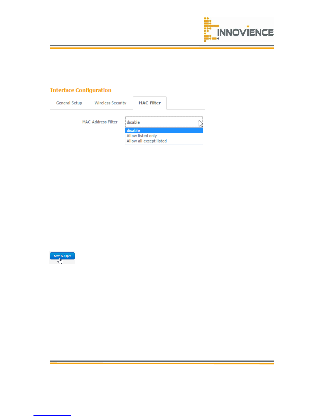
4.3 Mac filter
Figure 4.3.1
This wireless module supports Mac Address Control, which prevents unauthorized clients
from accessing your wireless network. A Mac adress is an unique ID that every network
capable device has to identify itself. By enabling the option Mac filtering the Access Point will
only accept incoming access requests of devices that are mentioned in the list. A Mac adress
usualy consists of 12 digits separated by a colon after every 2 digits.
• Enable wireless access control: enables the wireless access control function. You can
choose between ‘Allow listed only’ or ‘Allow all except listed’.
• Adding an address to the list: select the client to be added to the list and then click
"Save". You can add more clients by pressing the + sign.
• Remove an address from the list: if you want to remove a client from the "Mac List ",
select the client that you want to remove from the list and then click the - sign. Click
“Save” to save.
• Click “Save & Apply” at the bottom of the screen to save the above configuration.
Page 22
© Copyright 2016
Innovience International BV
Al rights reserved. Whole or partial reproduction is not permitted
without the written authorization of the copyright owner.
User manual OptoXSTM
Wifi module OXS-W11-EU
V 1.0, December 2016
Confidential
22
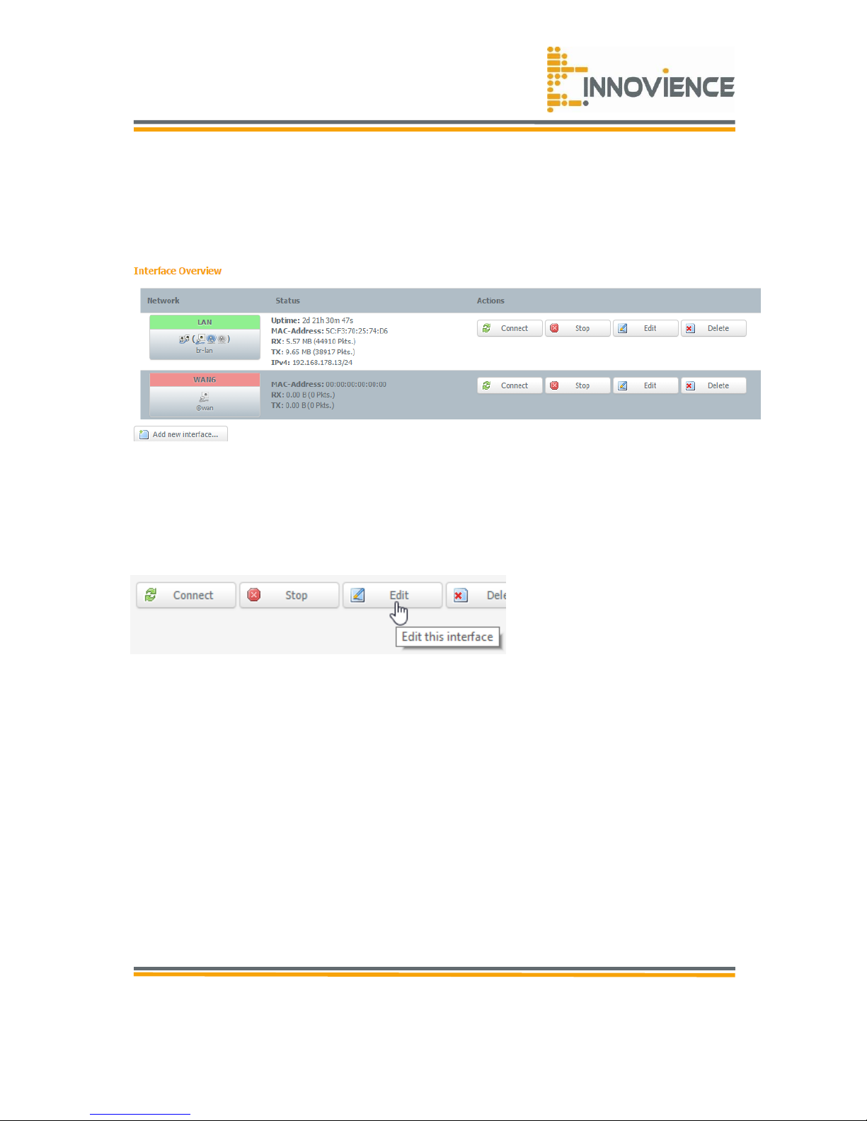
4.4 Interface settings
On this page you can see the LAN settings of you OptoXSTM Wifi module. By clicking ‘Edit’
you’ll enter the Settings page.
Figure 4.4.1
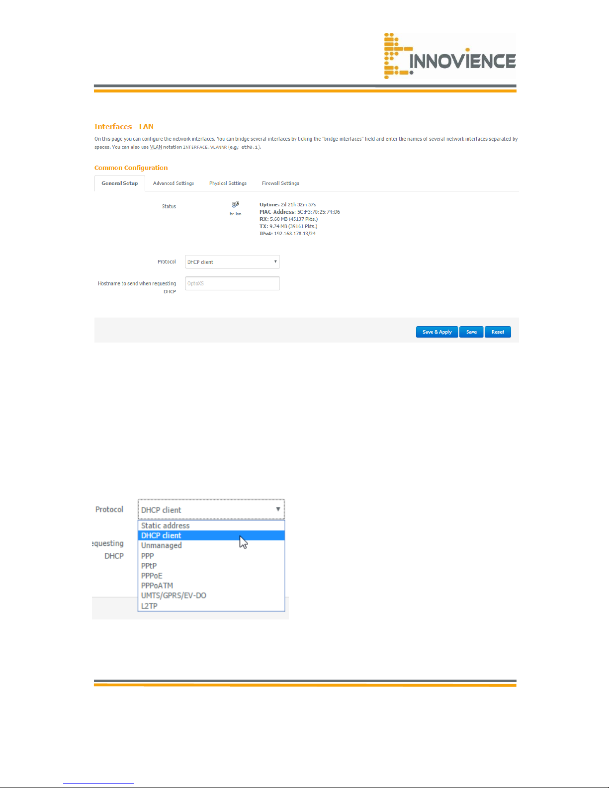
4.5 LAN
The LAN tab gives you the opportunity to change the IP settings of the OptoXSTM Wifi
module. Click on “Edit” if you desire to change any settings.
Figure 4.5.1
Page 23
© Copyright 2016
Innovience International BV
Al rights reserved. Whole or partial reproduction is not permitted
without the written authorization of the copyright owner.
User manual OptoXSTM
Wifi module OXS-W11-EU
V 1.0, December 2016
Confidential
23
As standard protocol the OptoXS
TM
Wifi module is assigned by default on “DHCP client”.
• DHCP Server: enabled by default. You can enable or disable the DHCP server. When
DHCP is disabled no IP-addresses are assigned to clients and you have to use static IPaddresses. When the DHCP server is enabled your computers will be assigned an IPaddress automatically until the lease time expires.
Figure 4.5.2
Page 24
© Copyright 2016
Innovience International BV
Al rights reserved. Whole or partial reproduction is not permitted
without the written authorization of the copyright owner.
User manual OptoXSTM
Wifi module OXS-W11-EU
V 1.0, December 2016
Confidential
24
For a most common system setup, in which your optoXS™ Wifi module is connected to your
main router (i.e. that router your ISP has provided for the internet service), you should keep
the setting “DHCP client”.
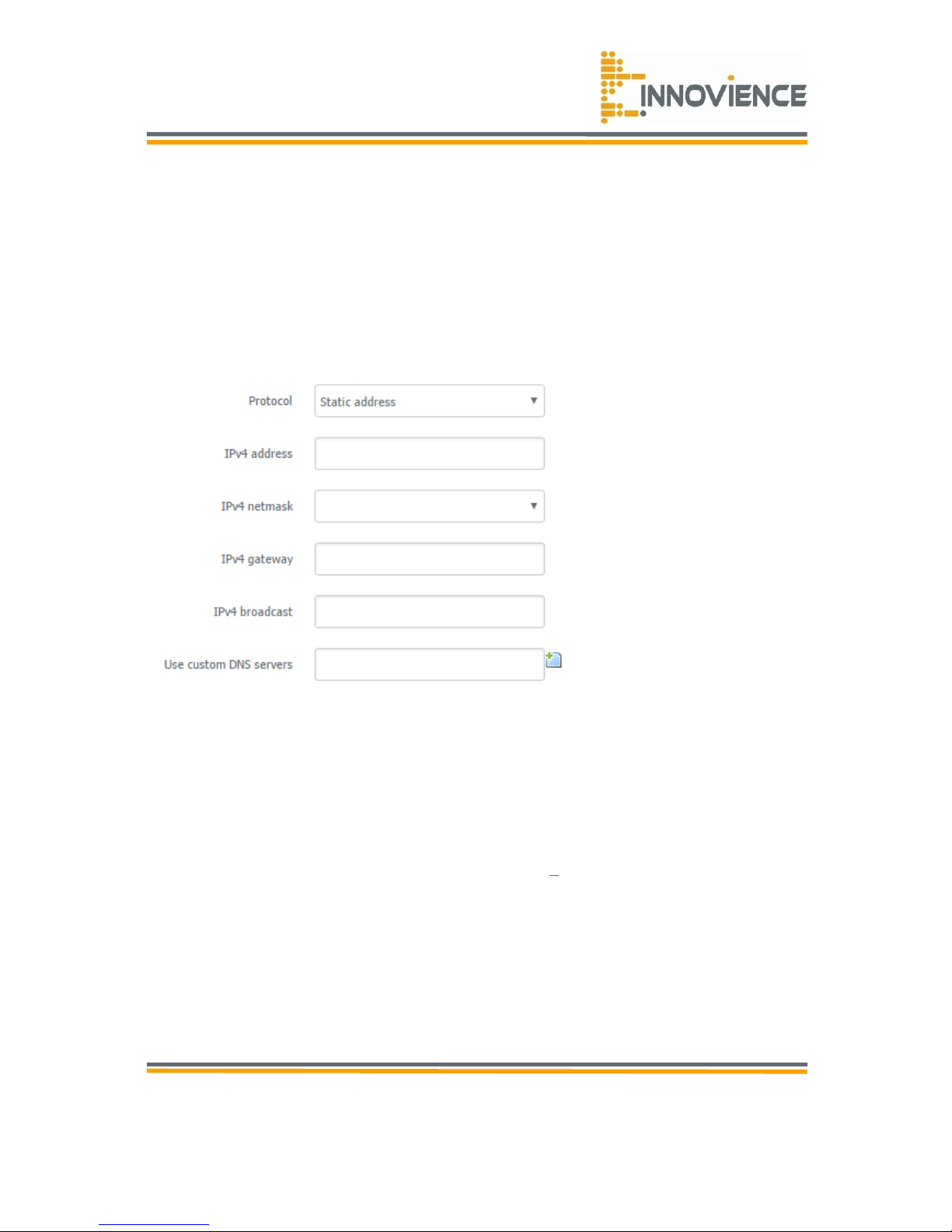
When a static adress is requested you could select the ‘Static Address’ at the drop down
menu.
Figure 4.5.3
• IPv4 address: it is the OptoXS
TM
Wifi module LAN IP-address. Use an IP scan to check if
an IP adress is available.
• IPv4 netmask: looks in a private environment like - 255.255.255.0. Specify a Subnet
Mask for your LAN segment.
• IPv4 Gateway: knowing the IP-address of the default gateway
(usually your router) on
your home or business network is important information if you want to successfully
troubleshoot a network problem or gain access to your router's web-based management.
• In most cases, the default gateway IP-address is the private IP address assigned to your
router. This is the IP-address that your router uses to communicate with your local home
network.
• Use custom DNS Server: normally a custom DNS server will be directed to the router or
server’s IP-address. In some occasions it is possible to use the ISP or a webserver’s IPaddress like Google.nl -> 8.8.8.8.
Page 25
© Copyright 2016
Innovience International BV
Al rights reserved. Whole or partial reproduction is not permitted
without the written authorization of the copyright owner.
User manual OptoXSTM
Wifi module OXS-W11-EU
V 1.0, December 2016
Confidential
25
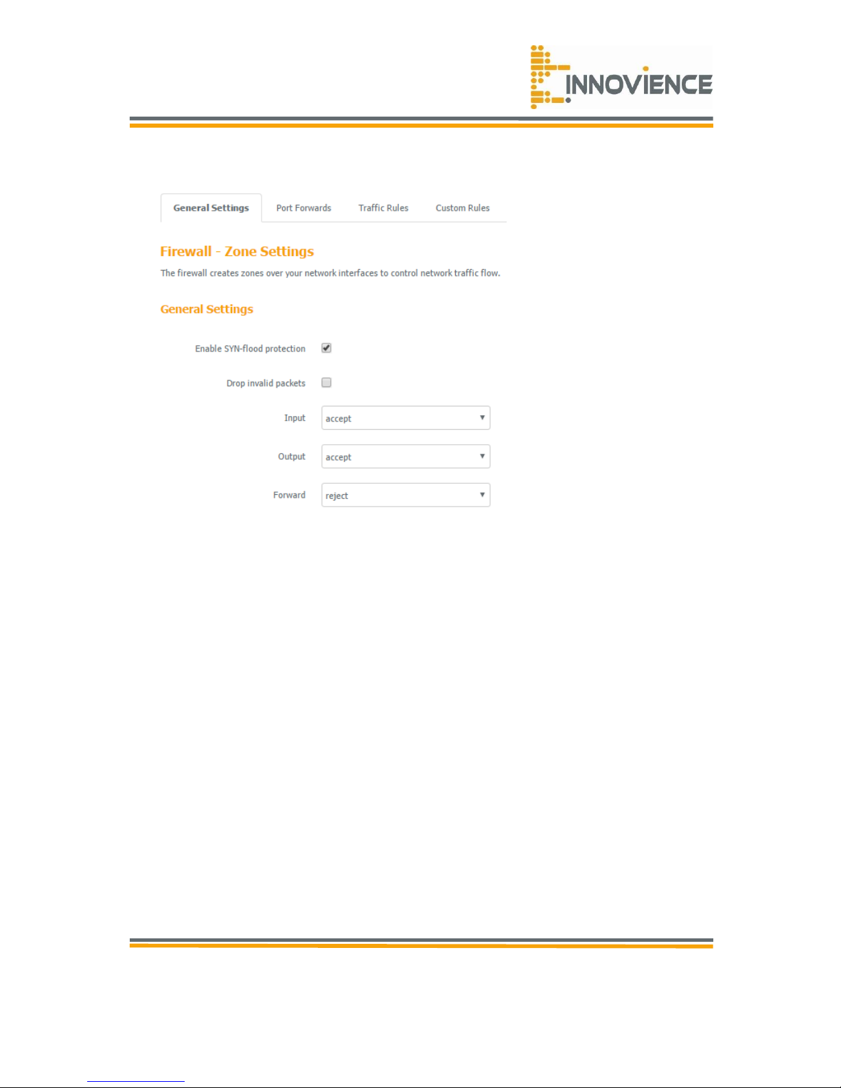
Figure 4.5.3
• Deny: if you select “Deny” then all clients will be allowed to access internet except for
the clients in the list below.
• Allow: if you select “Allow” then all clients will be denied to access internet except for the
PC’s in the list below.
• Filter client PC by Mac: check “Enable Mac Filtering” to enable Mac filtering.
• Add PC: fill in “Client PC Mac Address” and “Comment” of the PC that is allowed to
access the internet and then click “Add”. If you find any typo before adding it and want
to retype again, just click "Reset" and the fields will be cleared.
• Remove PC: if you want to remove some PC’s from the "Mac Filtering Table", select the
PC you want to remove in the table and then click "Delete Selected". If you want to
remove all PC’s from the table, just click the "Delete All" button. If you want to clear the
selection and re-select again, just click “Reset”.
• Filter client PC’s by IP: fill in “IP Filtering Table” to filter PC clients by IP.
• Add PC: you can click “Add PC” to add an access control rule for users by IP addresses.
• Remove PC: if you want to remove some PC’s from the "IP Filtering Table", select the PC
you want to remove in the table and then click “Delete Selected". If you want to remove
all PC’s from the table, just click the "Delete All" button.
• Click “Save & Apply” at the bottom of the screen to save the above configuration
Page 26

© Copyright 2016
Innovience International BV
Al rights reserved. Whole or partial reproduction is not permitted
without the written authorization of the copyright owner.
User manual OptoXSTM
Wifi module OXS-W11-EU
V 1.0, December 2016
Confidential
26
4.6 URL block
You can block access to some websites from particular PC’s by entering a full URL address or
just keywords of the website.
• Enable: URL Blocking Enable/Disable URL Blocking
• Add URL/keyword: fill in “URL/Keyword” and then click “Add”. You can enter the full URL
address or the keyword of the website you want to block.
• Remove URL/keyword: if you want to remove some URL keywords from the "Current URL
Blocking Table", select the URL keyword you want to remove in the table and then click
"Delete Selected". If you want to remove all URL keywords from the table, just click
"Delete All" button. If you want to clear the selection and re-select again, just click
“Reset”.
• Click “Save & Apply” at the bottom of the screen to save the above configuration.
4.7 Virtual server
Use the Virtual Server function when you want different servers/clients in your LAN to handle
different service/internet application type (e.g. email, FTP, webserver, etc.) from the
internet. Computers use numbers called port numbers to recognize a particular
service/internet application type. The Virtual Server allows you to re-direct a particular
service port number (from the internet/WAN port) to a particular LAN private IP-address and
it’s service port number.
• Enable Virtual Server: Enable Virtual Server.
• Local IP: this is the LAN client/host IP-address that the Public Port number packet will be
sent to.
• Local Port: this is the port number (of the above Private IP-host) that the below Public
Port number will be changed to when the packet enters your LAN (to the LAN
Server/Client IP).
• Type: select the port number protocol type (TCP, UDP or both). If you are unsure, then
leave it to the default “Both” setting.
• Public Port: enter the service (service/internet application) port number from the internet
that will be re-directed to the above Private IP-address host in your LAN
• Comment: the description of this setting.
• Add: fill in the "Private IP", "Private Port", "Type", “Public Port” and "Comment" of the
setting to be added and then click the + sign. Then this Virtual Server setting will be
added to the "Current Virtual Server Table" below.
• Reset: if you want to remove Virtual Server settings from the "Current Virtual Server
Table", select the Virtual Server settings you want to remove in the table and then click
"Delete Selected". If you want to remove all Virtual Server settings from the table, just
click the "Delete All" button. Click "Reset" will clear your current selections.
• Click “Save & Apply” at the bottom of the screen to save the above configuration.
Page 27

© Copyright 2016
Innovience International BV
Al rights reserved. Whole or partial reproduction is not permitted
without the written authorization of the copyright owner.
User manual OptoXSTM
Wifi module OXS-W11-EU
V 1.0, December 2016
Confidential
27
Chapter 5 Virtual server
5.1 ALG
An application gateway is an application program that runs on the router. When a client
program establishes a connection to a destination service, it connects to an application
gateway or proxy. The client then negotiates with the proxy server in order to communicate
with the destination service. In effect, the proxy establishes the connection with the
destination behind the firewall and acts on behalf of the client, hiding and protecting
individual computers on the network behind the firewall.
This creates two connections: one between the client and the proxy server and one between
the proxy server and the destination. Once connected, the proxy makes all packetforwarding decisions. Since all communication is conducted through the proxy server,
computers behind the firewall are protected.
Table 5.1 System requirements
Subjects
Specifications
Network requirements
• An OptoXS
TM
enabled wall-socket including at least a HUB or
Switch
• An Ethernet-based cable or DSL modem with DHCP-enabled
service
• IEEE 802.11n or 802.11g wireless clients
Electrical connection
Computer, tablet or Smartphone with the following:
Windows© , Macintosh, ChromeOS, Linux or Android based
operating system
• Wireless card
Browser requirements:
• Internet Explorer 7 or later
• Edge
• Firefox 12.0 or later
• Safari 4 or later
• Chrome 20.0 or later
Page 28

© Copyright 2016
Innovience International BV
Al rights reserved. Whole or partial reproduction is not permitted
without the written authorization of the copyright owner.
User manual OptoXSTM
Wifi module OXS-W11-EU
V 1.0, December 2016
Confidential
28
Table 5.2 Technical specifications (OXS-11n-EU (*)
Features
Advantages
Physical
dimensions
70mm x 70mm x 30mm (WxHxD)
Excl. mains power plugs (male)
Electrical
connection
CEE7/4 “schucko-connector” for outlets type E CEE7/5 (Belgium/France)
& type F CEE 7/3 (Germany/NL). Compatible with (earthed) power
wall-sockets common in Western Europe (DIN 49441 & NF C 61-314)
Input power
(mains)
100-240V AC, 50/60Hz
Power
consumption
Max. 5 W (operation)
Power
throughput
Max. 10A@230Vac
Data connection
Rx/Tx via OptoXSTM optical POF cable mounted in wall-socket
Standard
IEEE 802.11n/g/b/a, IEEE 802.3i, IEEE 802.3u, IEEE 802.3z, IEEE
802.3x, IEEE 802.3Q, IEEE 802.3p, ANSI/IEEE 802.3 Nway Auto
negotiation, IEEE 802.1AX
Frequency
2.4 GHz band
Data rate
Up to 150 Mb/s @ 40 MHz (2.4 Ghz)
Up to 72,2 Mb/s @ 20 MHz (2.4 Ghz) (1
Security
WPA, WPA2**, WEP, WPS, up to 152-Bit encryption
Advanced
functions
Power setting to max 20dBm (100mW)
Interfaces
POF optical input/output, 230V AC power outlet earthed
LED indicators
Front LED white
Status: continuous/blinking/off
Antennas
Microstrip antenna (internal)
Page 29

© Copyright 2016
Innovience International BV
Al rights reserved. Whole or partial reproduction is not permitted
without the written authorization of the copyright owner.
User manual OptoXSTM
Wifi module OXS-W11-EU
V 1.0, December 2016
Confidential
29
Table 5.2 Technical specifications (OXS-11n-EU (*) continuation
Features
Advantages
CPU
Realtek RTL8192E, RTL8881am
Operating system
Linux 3.10 by customized OpenWRT barrier breaker v14.07, incl. Luci
Innovience International theme
VLAN support
802.1Q VLAN Support v1.8
QoS
IEEE 802.3x Flow Control
WAN type
IPv4: compatible with Dynamic IP, Static IP, PPPoE, PPTP internet
connections
IPv6: compatible with Native, PPPoX (PPPoA and PPPoE), DS Lite, 6RD
internet connections
Quality of service
Not available
Port forwarding
Port triggering, NAT
Dynamic DNS
OpenDNS
Access control
IMAC filter
(*
Referenced with firmware version OpenWrt Barrier Breaker 14.07/LuCI Branch (0.12+git-15.112.69076-
6153b99)
(1
Theoretical wireless signal rate based on IEEE standard of 802.11a, b, g, n, chipset used. Actual throughput
may vary. Network conditions and environmental factors lower actual throughput rate. All specifications are
subject to change without notice.
Page 30
© Copyright 2016
Innovience International BV
Al rights reserved. Whole or partial reproduction is not permitted
without the written authorization of the copyright owner.
User manual OptoXSTM
Wifi module OXS-W11-EU
V 1.0, December 2016
Confidential
30
6 Recovery and update features
6.1 Backup/Flash firmware
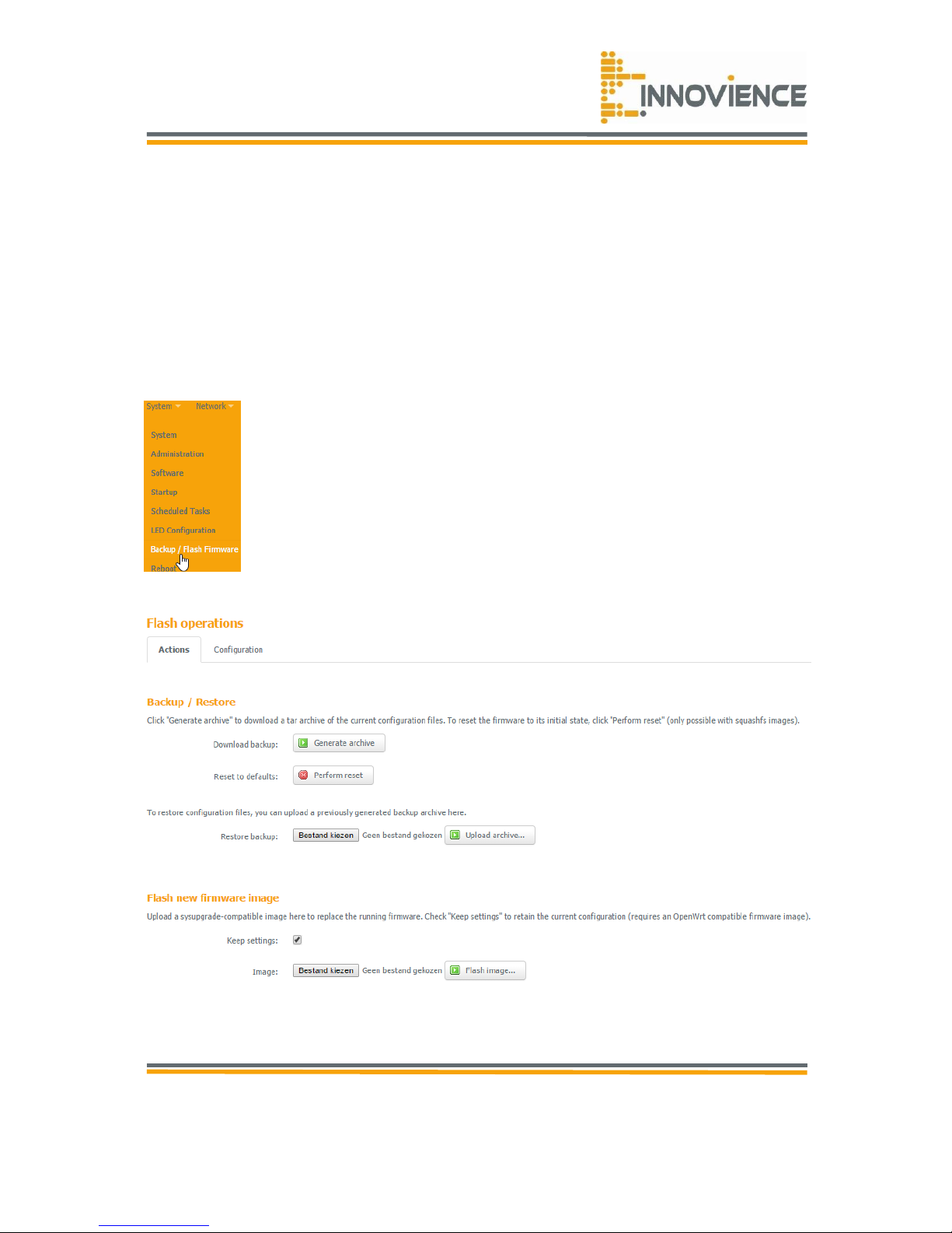
Navigate to “TAB – System -> Backup/Flash Firmware”. Use the "Generate archive" button
to save the current configuration to a file on your PC. You can then use the "Restore backup"
button to restore the saved configuration to the module. Alternatively, you can use the
"Reset to Factory Defaults” button to force the module to perform a power reset and restore
the original factory settings.
Figure 6.1
Figure 6.2
Page 31

© Copyright 2016
Innovience International BV
Al rights reserved. Whole or partial reproduction is not permitted
without the written authorization of the copyright owner.
User manual OptoXSTM
Wifi module OXS-W11-EU
V 1.0, December 2016
Confidential
31
This page also allows you to upgrade the OptoXSTM Wifi module’s system firmware. To
upgrade the firmware of your OptoXSTM Wifi module, you need to download the firmware file
to your local hard disk and enter that file name and path in the appropriate field on this
page. You can also use the browse button to find the firmware file on your PC.
Once you’ve selected the new firmware file, click “Save & Apply” at the bottom of the screen
to start the upgrade process.
Page 32

© Copyright 2016
Innovience International BV
Al rights reserved. Whole or partial reproduction is not permitted
without the written authorization of the copyright owner.
User manual OptoXSTM
Wifi module OXS-W11-EU
V 1.0, December 2016
Confidential
32
Chapter 7 Troubleshooting guide
Problem
What to do
The module does not fit into
my power socket
• Check whether you do have the correct module in your
hand. EU-models should fit when you are living in The
Netherlands, Germany, Belgium, France, Spain and Italy.
When you live in the UK, Eastern-Europe, Portugal and
Scandinavian countries, you do need a different model.
Contact your local dealer or reseller.
I do not have any earthed
power sockets in my home
• The OptoXS
TM
Wifi module also can be plugged into an
un-earthed power socket. Under normal and intended use
the electrical safety is guaranteed.
I have plugged-in the module
and connected my computer
as a wireless client, but I have
no internet connection.
• If the white-coloured LED of the module is NOT emitting,
then your wall-socket is not powered. Check your circuit
breakers in your utility cabinet. In case of any doubt
contact your local electrician.
• If the white coloured LED is constantly shining, you should
check wether you have plugged in the module in an
OptoXSTM enabled power socket. To do that, you should
unplug the module and - while keeping a minimum
distance of 33 cm - look at the wall-outlet- you should see
two tiny holes. From the right-handed one, a blinking redcoloured light is emitted. If any light is absent you should
check if your OptoXSTM HUB/Switch is powered and is
emitting blinking red-coloured signals.
• Rotate the module. You may have plugged-in the module
up-side down. Unplug the module and turn it around. The
two tiny holes from the module should be oriented
upwards.
Page 33

© Copyright 2016
Innovience International BV
Al rights reserved. Whole or partial reproduction is not permitted
without the written authorization of the copyright owner.
User manual OptoXSTM
Wifi module OXS-W11-EU
V 1.0, December 2016
Confidential
33
Problem
What to do
I have plugged in my module
in an optoXSTM enabled wallsocket, do have internet
access but cannot login into it
to change some settings.
• You need to ensure that your computer is in the same IP
SubnetMask to connect to the web-based utility. By default
this is 255.255.255.0. In case of doubt you should check
with your DSL/cable modem.
• Make sure you have an updated Java-enabled web
browser.
• You need the module’s IP-address for your browser. You
need to login into your DSL/cable modem for this. Go to
page 16 of this manual.
• Disable any internet security software running on the
computer. Software firewalls such as Zone Alarm, Black
Ice, Sygate, Norton Personal Firewall and Windows® may
block access to the configuration pages. Check the help
files included with your firewall software for more
information on disabling or configuring it.
• Check the signal level. Move closer to the module to
improve the level or try with another OptoXSTM enabled
wall socket.
• First of all you should keep the modules Wifi channel
selection to “Auto”, If that does not help, you should
select a Wifi channel that shows less interference. For this
you have to login into your module with a web browser.
You need the module’s IP-address for this (see page 15).
• The module should not be obstructed by objects in its
immediate surrounding area.
I want to update/upgrade my
module.
• You should NOT attempt to flash an OpenWRT firmware
that has not been officially released on Innovience
International’s website. You may end-up with a bricked
module that has become unusable.
• There is no need to upgrade the module’s firmware during
it’s lifetime.
I have several OptoXS
TM
Wifi
modules in my home and I
desire seemless roaming from
one room to another.
• Roaming requires that you configure each module to
create a wireless network with the SAME SSID (“OptoXS
TM”
by default) AND login key (“00000000” by default). Also
you should use different channels in your network.
Page 34

© Copyright 2016
Innovience International BV
Al rights reserved. Whole or partial reproduction is not permitted
without the written authorization of the copyright owner.
User manual OptoXSTM
Wifi module OXS-W11-EU
V 1.0, December 2016
Confidential
34
Problem
What to do
I did forget my password.
• The only option left is to reset your module to factory
default values. For this you should push the small reset
button for at least 10 seconds. Small reset is 5 seconds.
The module will restart itself. By default there is NO
password to login into the module.
 Loading...