

Page 1

Doc: User Manual DA3
GA02091 Version: 1.1
Page 2

<< Back to Contents
Copyright © Innovative Technology Ltd 2017 Doc: User Manual DA3 GA02091
Version: 1.1
Page 1 of 42
Document Name:
User Manual DA3 GA02091
Document Version:
1.1
Date of Release:
05.12.2017
TABLE OF CONTENTS
1 DOCUMENT INTRODUCTION .................................................................................................................. 3
1.1 MANUAL AMENDMENTS ................................................................................................................................. 3
1.2 COPYRIGHT .................................................................................................................................................. 3
1.3 LIMITED WARRANTY ...................................................................................................................................... 3
1.4 PRODUCT SAFETY INFORMATION ...................................................................................................................... 4
1.5 DISCLAIMER ................................................................................................................................................. 4
2 PRODUCT INTRODUCTION ...................................................................................................................... 6
2.1 GENERAL DESCRIPTION ................................................................................................................................... 6
2.2 KEY FEATURES .............................................................................................................................................. 6
2.3 COMPONENT OVERVIEW ................................................................................................................................ 6
2.3.1 DA3 Kit Variants .............................................................................................................................. 7
2.3.1.1 DA3 SMART Update Tool components ................................................................................................. 7
2.3.1.2 Standard DA3-Kit components .............................................................................................................. 7
2.3.1.3 DA3 Pre-programmed ........................................................................................................................... 7
3 MECHANICAL INSTALLATION .................................................................................................................. 8
3.1 CONNECTING THE DA3 .................................................................................................................................. 8
3.1.1 Driver Installation ........................................................................................................................... 8
3.1.1.1 Windows 7 Driver Install ....................................................................................................................... 9
3.1.1.2 Windows 8/10 Driver Install ............................................................................................................... 11
3.1.2 Connecting the DA3 to a Computer .............................................................................................. 12
3.1.3 Connecting the DA3 in the Field for Update ................................................................................. 13
3.1.3.1 Option 1 – Power Supply via Host Machine ........................................................................................ 13
3.1.3.2 Option 2 – Power Supply via external Power Supply .......................................................................... 14
4 SOFTWARE INSTALLATION AND CONFIGURATION ................................................................................ 15
4.1 SOFTWARE OVERVIEW ................................................................................................................................. 15
4.1.1 Device Programming System (DPS) ............................................................................................... 15
4.1.1.1 General Description ............................................................................................................................ 15
4.1.1.2 Firmware Update/Change on the DA3 ................................................................................................ 15
4.1.1.3 Adding datasets to the dataset library ................................................................................................ 16
4.1.1.4 Storing files on the DA3 ...................................................................................................................... 17
4.1.1.5 Tagging files for override .................................................................................................................... 18
4.1.2 NV Memory Card Utilities ............................................................................................................. 19
4.1.2.1 General Description ............................................................................................................................ 19
4.1.2.2 Format for log data ............................................................................................................................. 20
4.1.2.3 Format for dataset update card (NV200 Range only) ......................................................................... 21
4.1.2.4 Format for option update card (NV200 Range only) ........................................................................... 24
4.1.2.5 Format for SSP packet log ................................................................................................................... 24
4.1.2.6 Format for Hostless Refill (NV200 Range only) ................................................................................... 24
4.1.2.7 Format for initialisation (NV200 Range only) ...................................................................................... 24
4.1.2.8 Upload Log Data .................................................................................................................................. 25
5 OPERATION AND SETUP ....................................................................................................................... 26
5.1 STANDARD FIRMWARE ................................................................................................................................. 26
5.1.1 General Description ...................................................................................................................... 26
5.1.2 BNV Match Download................................................................................................................... 26
Page 3

<< Back to Contents
Copyright © Innovative Technology Ltd 2017 Doc: User Manual DA3 GA02091
Version: 1.1
Page 2 of 42
5.1.3 Set BNV to check mode ................................................................................................................. 28
5.1.4 Serial Comm Monitor .................................................................................................................... 28
5.1.5 Collect Note Data .......................................................................................................................... 28
5.1.6 Copy A to DA3 ............................................................................................................................... 29
5.1.7 Copy DA3 to A ............................................................................................................................... 29
5.1.8 Copy A to B .................................................................................................................................... 30
5.1.9 Data Logging ................................................................................................................................. 31
5.1.9.1 General Description ............................................................................................................................ 31
5.1.9.2 Requirements...................................................................................................................................... 31
5.1.9.3 Setup ................................................................................................................................................... 31
5.1.9.4 Collecting Data .................................................................................................................................... 32
5.1.9.5 Extract the Data .................................................................................................................................. 32
5.2 SMART UPDATE FIRMWARE ......................................................................................................................... 33
5.2.1 General Description ...................................................................................................................... 33
5.2.2 Requirements ................................................................................................................................ 33
5.2.3 Setup ............................................................................................................................................. 34
5.2.4 Update Procedure ......................................................................................................................... 35
6 FIRST LEVEL SUPPORT ........................................................................................................................... 36
6.1 LED ERROR FLASH CODES ............................................................................................................................. 36
7 TECHNICAL DATA .................................................................................................................................. 37
7.1 ENVIRONMENTAL REQUIREMENTS .................................................................................................................. 37
7.2 POWER REQUIREMENTS ............................................................................................................................... 37
7.2.1 Supply Voltages ............................................................................................................................. 37
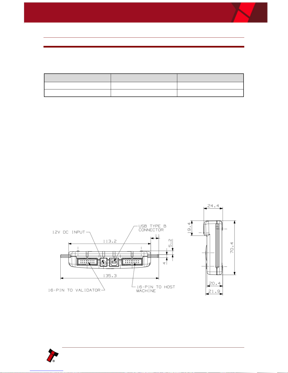
7.3 DIMENSIONS .............................................................................................................................................. 37
8 COMPLIANCES AND APPROVALS .......................................................................................................... 38
8.1 EC DECLARATION OF CONFORMITY ................................................................................................................. 38
9 APPENDIX ............................................................................................................................................. 39
9.1 CABLE DRAWINGS ....................................................................................................................................... 39
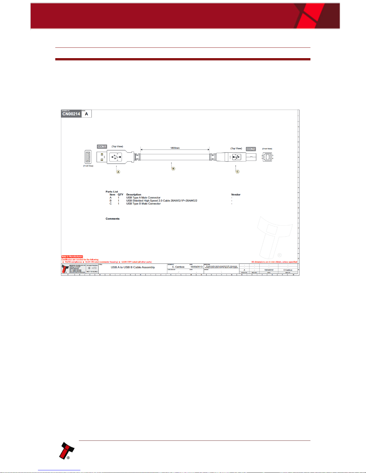
9.1.1 CN00214 – USB A to B cable assembly ......................................................................................... 39
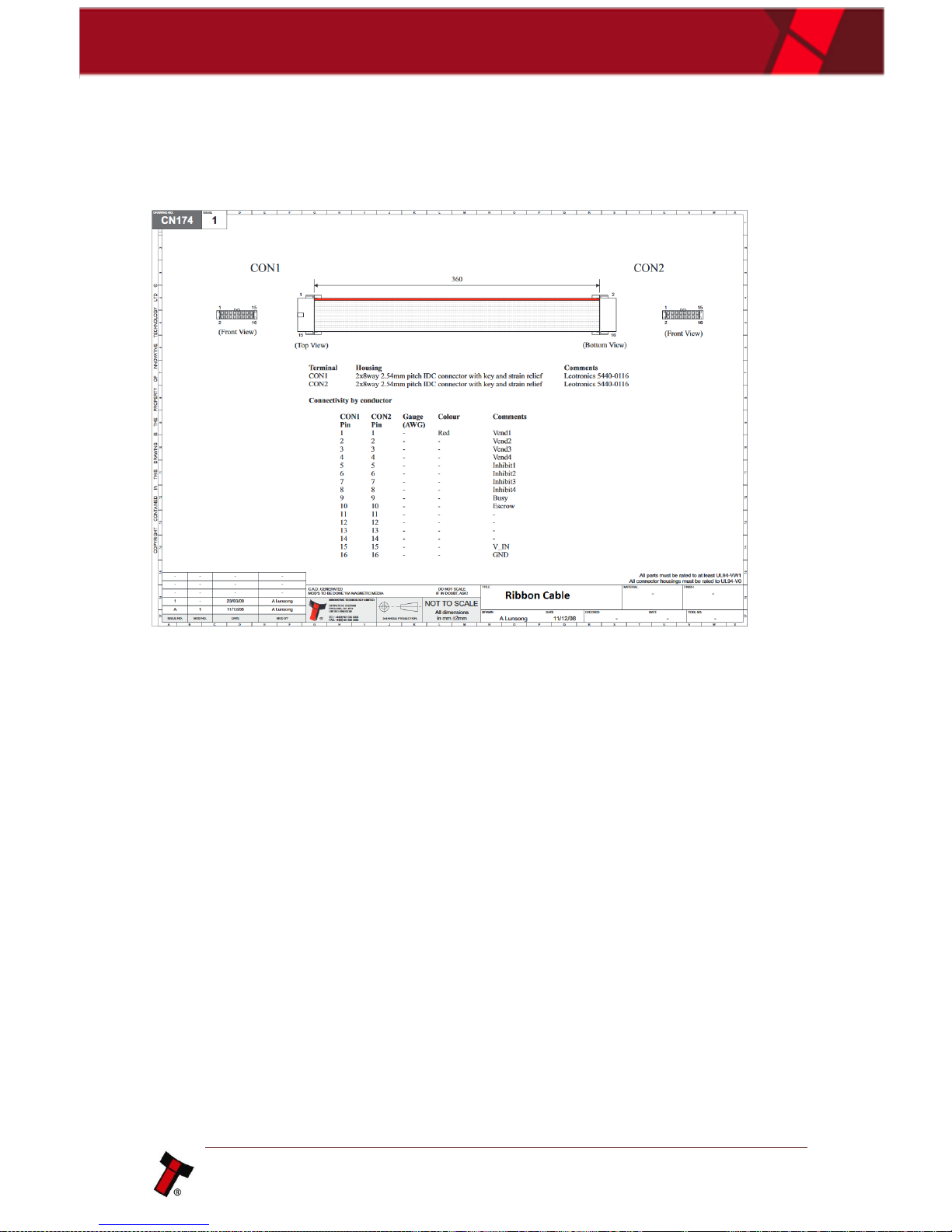
9.1.2 CN174 – Ribbon Cable ................................................................................................................... 40
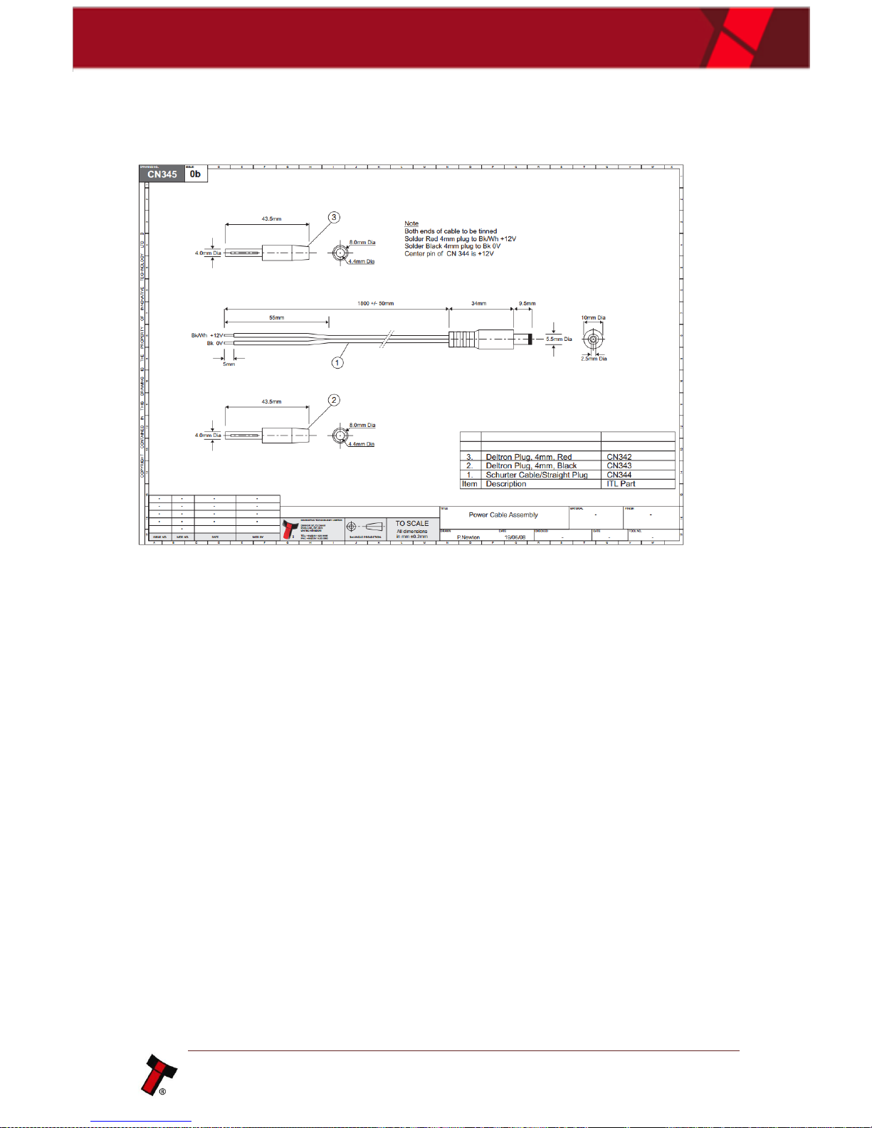
9.1.3 CN00345 - DA3 Power Cable ......................................................................................................... 41
9.2 SWITCHING ITL DEVICES TO PROGRAMMING MODE (SSP) .................................................................................. 42
9.3 FIRMWARE IDENTIFIER.................................................................................................................................. 42
Page 4
<< Back to Contents
Copyright © Innovative Technology Ltd 2017 Doc: User Manual DA3 GA02091
Version: 1.1
Page 3 of 42
1 DOCUMENT INTRODUCTION
1.1 Manual Amendments
Rev.
Date
Amendment Details
Issued by
1.0
20.06.2017
First Issue
SG
1.1
05.12.2017
- Layout amendment
- Dimensions added
- Wording amendments
- LED Error Flash Code Troubleshooting added
SG
1.2 Copyright
This manual set is Copyright © Innovative Technology Ltd. 2016. No part of this
publication may be reproduced in any form or by any means used to make any
derivative such as translation, transformation, or adaptation without permission from
Innovative Technology Ltd. The contents of this manual set may be subject to
change without prior notice.
1.3 Limited Warranty
Innovative Technology Ltd warrants each of its hardware products to be free from
defects in workmanship and materials under normal use and service for a period
commencing on the date of purchase from Innovative Technology Ltd or its
Authorized Reseller, and extending for the length of time stipulated by Innovative
Technology Ltd.
A list of Innovative Technology Ltd offices can be found on the ITL website. If the
product proves defective within the applicable warranty period, Innovative
Technology Ltd will repair or replace the product. Innovative Technology Ltd shall
have the sole discretion whether to repair or replace, and any replacement product
supplied may be new or reconditioned.
The foregoing warranties and remedies are exclusive and are in lieu of all other
warranties, expressed or implied, either in fact or by operation of law, statutory or
otherwise, including warranties of merchantability and fitness for a particular
purpose.
Innovative Technology Ltd shall not be liable under this warranty if it’s testing and
examination disclose that the alleged defect in the product does not exist or was
caused by the customer's or any third person's misuse, neglect, improper installation
or testing, unauthorized attempts to repair, or any other cause beyond the range of
the intended use. In no event will Innovative Technology Ltd be liable for any
damages, including loss of profits, cost of cover or other incidental, consequential or
indirect damages arising out the installation, maintenance, use, performance, failure
or interruption of an Innovative Technology Ltd product, however caused.
Page 5
<< Back to Contents
Copyright © Innovative Technology Ltd 2017 Doc: User Manual DA3 GA02091
Version: 1.1
Page 4 of 42
1.4 Product Safety Information
Throughout this user manual, we may draw your attention to key safety points that
you should be aware of when using or maintaining the product.
These safety points will be highlighted in a box, like this:
Caution!
This is an example text.
This user manual and the information it contains is only applicable to the model
stated on the front cover, and must not be used with any other make or model.
1.5 Disclaimer
Innovative Technology Ltd is not responsible for any loss, harm, or damage caused
by the installation and use of this product. This does not affect your local statutory
rights. If in doubt please contact Innovative Technology for details of any changes.
Innovative Technology Ltd has a policy of continual product improvement. As a
result the products supplied may vary from the specification described here.
Innovative Technology Ltd does not accept liability for any errors or omissions
contained within this document. Innovative Technology Ltd shall not incur any
penalties arising out of the adherence to, interpretation of, or reliance on, this
standard.
Page 6
<< Back to Contents
Copyright © Innovative Technology Ltd 2017 Doc: User Manual DA3 GA02091
Version: 1.1
Page 5 of 42
Safety Notice! Read before using this product!
Safety Notice - Warning. Ensure power is removed before allowing access to the inside of this product.
Ensure any static build up is discharged before allowing access to any part of this product or media
contained. Always earth this product/base plate in accordance with the manual.
For use only in or with complete equipment where the acceptability of the combination is determined by
UL LLC. When installed in an end-product, consideration must be given to the following:
• The power supply terminals and/or connectors are: Not investigated for field wiring
• The investigated Pollution Degree is: 2
• The following end-product enclosures are required: Mechanical, Fire
Sicherheitshinweis – Warnung: Es muss sichergestellt werden, dass das Gerät von der
Versorgungsspannung getrennt wird, bevor ein Eingriff in das Innere des Gerätes erfolgt. Es muss
sichergestellt werden, dass jegliche statische Aufladung des Gerätes entladen wird, bevor auf das Gerät
oder auf innerhalb des Gerätes befindliche Objekte zugegriffen wird. Die Erdung des Gerätes muss immer
gemäß Handbuch erfolgen.
Nur für die Verwendung in oder mit kompletter Ausstattung, dessen Eignung und Kombination von der UL
LLC ermittelt wurde. Bei der Installation in einem Endproduckt, muss folgendes berücksichtigt werden:
• Die Spannungsversorgungsklemmen und/oder Verbinder sind: Feldverkabelung wurde nicht
untersucht
• Der untersuchte Verschmutzungsgrad ist: 2
• Folgende Anforderungen an die Gehäuse des Endproduktes sind gefordert: Mechanisch, Feuer
Aviso de seguridad: Asegúrese de que la alimentación está desconectada y de que toda la energía
estática es descargada antes de manipular este producto. Conecte a tierra la chapa base de la manera que
se indica en el manual.
Solo para uso con dispositivos con los cuales la compatibilidad ha sido certificada por UL LLC. Tras su
instalación en producto acabado, tener en cuenta lo siguiente:
• Los conectores y terminales de alimentación son: No se ha investigado/especificado cableado
externo.
• El grado de contaminación determinado es: 2
• Los siguientes manuales/certificados de producto final son requeridos: Mecánico, Fuego
Avis de sécurité : Assurez-vous que l'alimentation est coupée et que toute l'énergie statique est
déchargé avant de manipuler ce produit. Connecter à la terre, la plaque de base à la manière indiquée
dans le manuel.
A utiliser Seulement avec les dispositifs dont la compatibilité a été certifiée par UL LLC. Après son
installation dans le produit fini, prendre en considération ce qui suit:-
• Les connecteurs et les bornes d'alimentation sont : cela n’a pas été étudié/spécifié câblage
externe.
• Le degré de contamination déterminé est: 2
• Les manuels suivants / les certificats du produit final sont nécessaires : mécanique, incendie
Bezpečnostní upozornění. Před manipulací uvnitř tohoto produktu se ujistěte, že je produkt odpojen od
zdroje elektrického napětí. Ujistěte se, že jakýkoliv elektrostatický náboj byl vybit před manipulací s
jakoukoliv částí tohoto produktu nebo obsaženým médiem. Vždy uzemněte tento produkt/základovou
desku v souladu s návodem.
Pouze pro použití v nebo s kompletním vybavením, kde je přijatelnost kombinace určena UL LLC. Při
instalaci v konečném produktu je třeba zvážit nasledující:
• Napájecí svorky a/nebo konektory: Nejsou sledované pro externí kabeláž
• Sledovaný stupeň znečištění je: 2
• Následující krytí konečného produktu jsou požadované: Mechanické, Protipožární
Page 7
<< Back to Contents
Copyright © Innovative Technology Ltd 2017 Doc: User Manual DA3 GA02091
Version: 1.1
Page 6 of 42
2 PRODUCT INTRODUCTION
2.1 General Description
The DA3 is a hand-held validator programming system that enables the user to re-program
ITL banknote validators in the field, without the use of a PC.
Dataset and firmware files for different validator models can be stored on the DA3.
Once programmed the user can update or override existing software as well as test the
functionality of the validator, away from the host machine.
2.2 Key Features
• Re-program ITL banknote validators in the field, without the use of a PC
• Update or override existing software
• Test the functionality of the validator
• Configure ITL data flash cards for various functionality
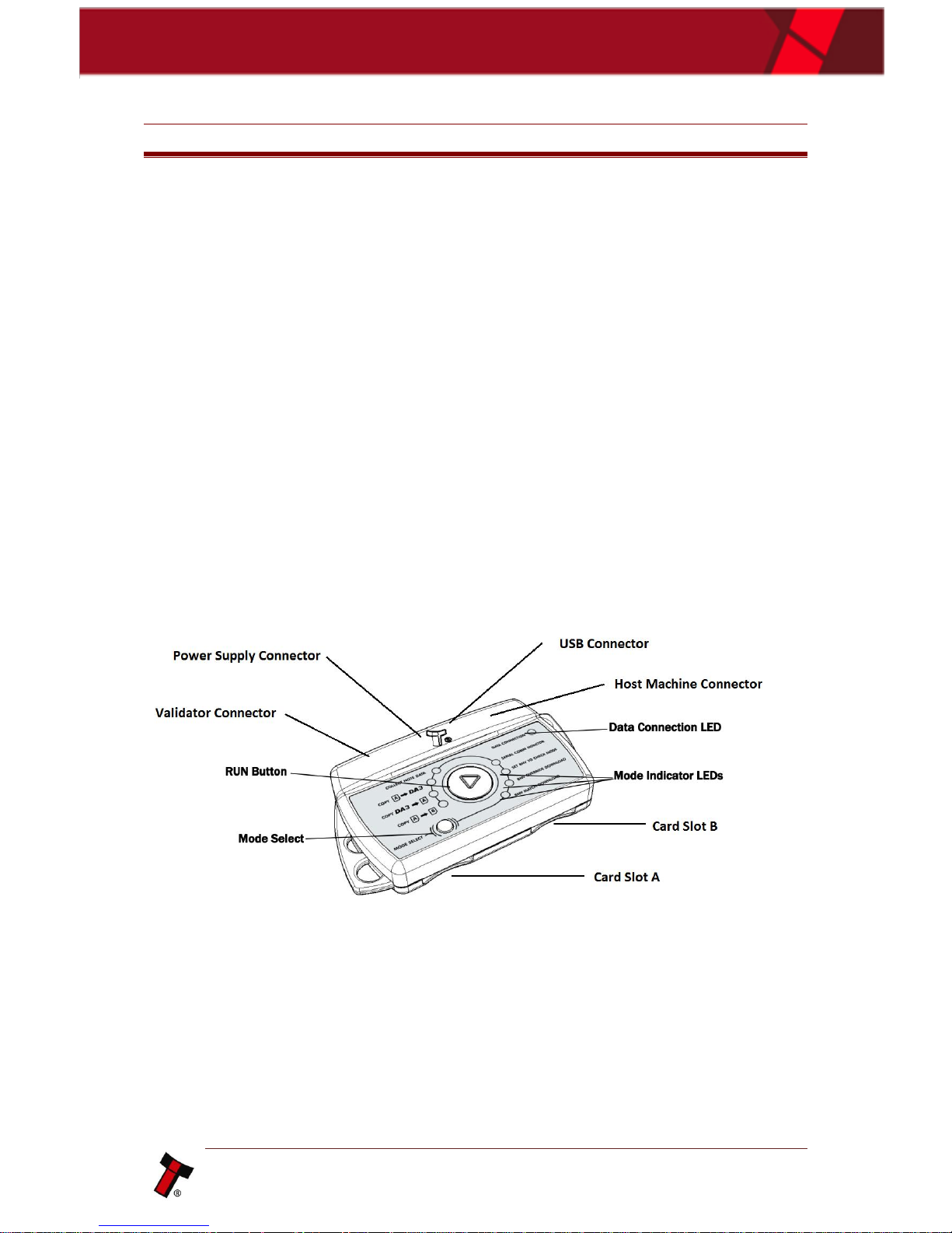
2.3 Component Overview
Page 8
<< Back to Contents
Copyright © Innovative Technology Ltd 2017 Doc: User Manual DA3 GA02091
Version: 1.1
Page 7 of 42
2.3.1 DA3 Kit Variants
2.3.1.1 DA3 SMART Update Tool components
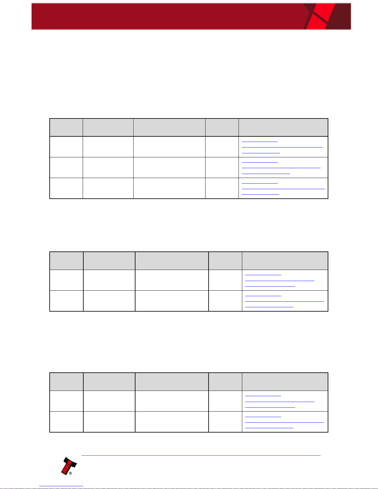
A DA3 and a pre-programmed SD card including all dataset files for current ITL
validators. The Kit consist of the following cables and Accessories:
Type
ITL Part
Number
Description
Quantity
Details
Cable
CN174
NV9 / NV10 Ribbon Cable
1
http://innovativetechnology.com/shop/cables/nv9-nv10ribbon-cable-detail
Cable
CN214
USB A to B Cable Assembly
1
http://innovativetechnology.com/shop/cables/usb-a-tob-cable-assembly-detail
SD card
IC02017
Blank SD Card 4GB
1
http://innovativetechnology.com/shop/accessories/blanksd-card-4gb-detail
2.3.1.2 Standard DA3-Kit components
Blank DA3 unit with all required cables. The Kit consist of the following cables:
Type
ITL Part
Number
Description
Quantity
Details
Cable
CN174
NV9 / NV10 Ribbon Cable
1
http://innovativetechnology.com/shop/cables/nv9nv10-ribbon-cable-detail
Cable
CN214
USB A to B Cable Assembly
1
http://innovativetechnology.com/shop/cables/usb-a-tob-cable-assembly-detail
2.3.1.3 DA3 Pre-programmed
DA3 unit Pre-programmed to customer specific requirements. The Kit consist of the
following cables:
Type
ITL Part
Number
Description
Quantity
Details
Cable
CN174
NV9 / NV10 Ribbon Cable
1
http://innovativetechnology.com/shop/cables/nv9nv10-ribbon-cable-detail
Cable
CN214
USB A to B Cable Assembly
1
http://innovativetechnology.com/shop/cables/usb-a-tob-cable-assembly-detail
Page 9
<< Back to Contents
Copyright © Innovative Technology Ltd 2017 Doc: User Manual DA3 GA02091
Version: 1.1
Page 8 of 42
3 MECHANICAL INSTALLATION
3.1 Connecting the DA3
3.1.1 Driver Installation
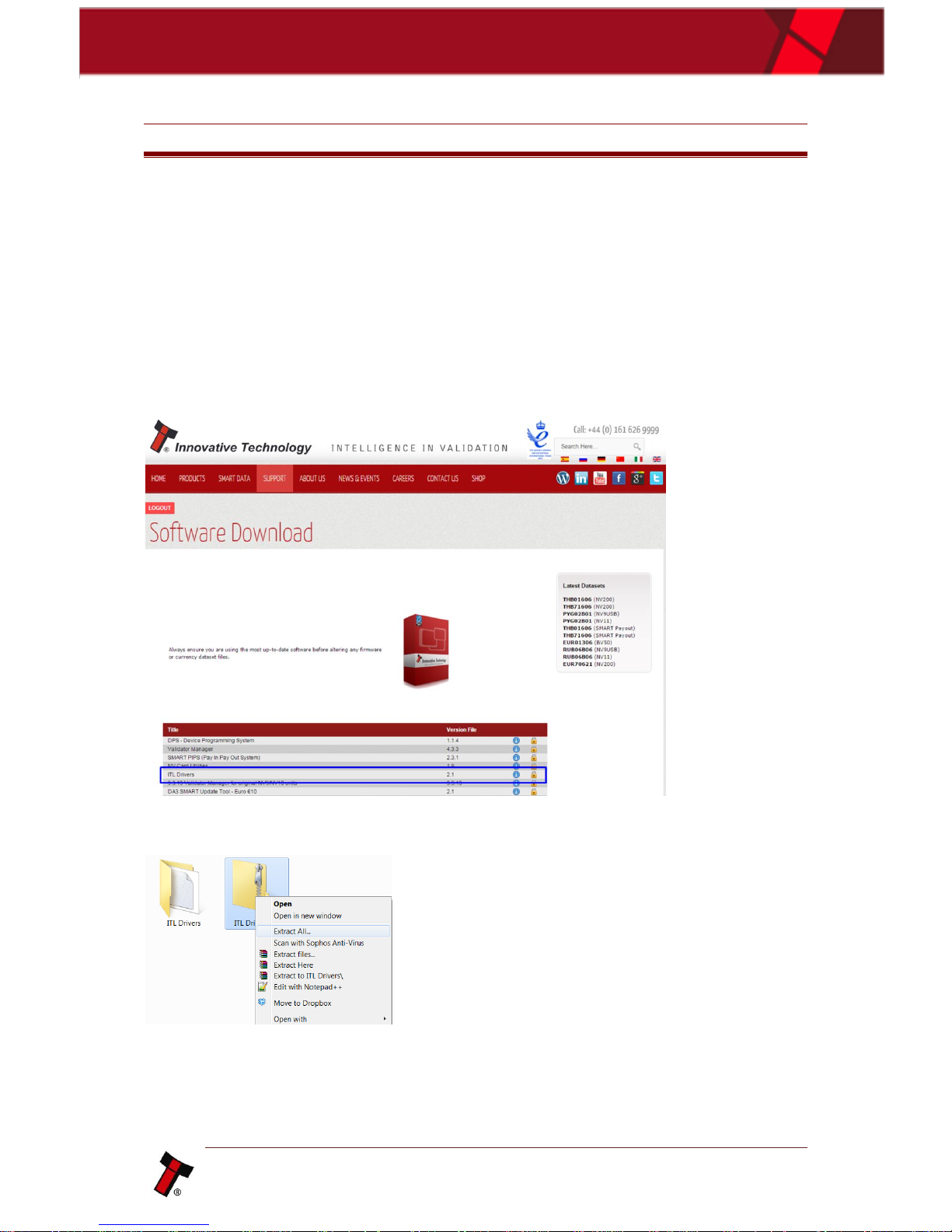
The ITL drivers allow you to connect any of our validators to a compatible Windows
device. On the website is a driver package for download available.
This can be downloaded from the Software download page on support, to download
click on the padlock to the right of the screen. To Download the package, you would
need to log-in/Register on the website.
Once downloaded you will need to extract the drivers from the zip file, this can be
done by right clicking and selecting extract all.
This will create a new folder with the extracted files.
Page 10
<< Back to Contents
Copyright © Innovative Technology Ltd 2017 Doc: User Manual DA3 GA02091
Version: 1.1
Page 9 of 42
3.1.1.1 Windows 7 Driver Install
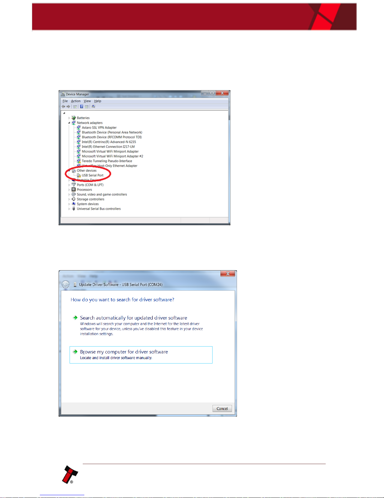
Now navigate to device manager, an unknown device should be present, as shown
in the figure below.
Right click and select ‘Update Driver Software’, a screen will appear asking you to
either search Windows update for the correct driver or to ‘Browse your computer’,
you will need to click browse my computer.
Page 11
<< Back to Contents
Copyright © Innovative Technology Ltd 2017 Doc: User Manual DA3 GA02091
Version: 1.1
Page 10 of 42
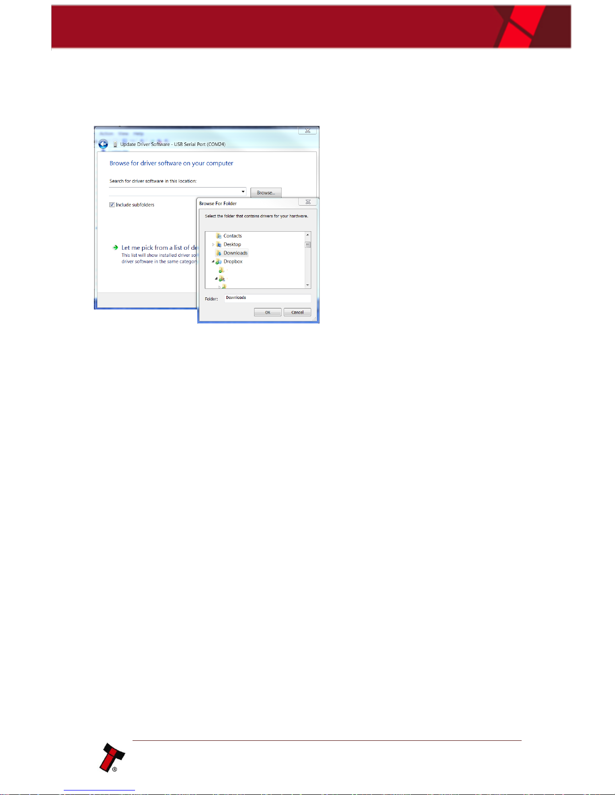
Now navigate to the folder where the drivers were extracted, as shown below and
choose the required DA3 driver pending on your system (“NVxx, BVxx, DA3 - 32 bit”
or “NVxx, BVxx, DA3 - 64 bit”):
Click next then the driver will install, once the process has completed the interface
device will be visible under ports.
Page 12
<< Back to Contents
Copyright © Innovative Technology Ltd 2017 Doc: User Manual DA3 GA02091
Version: 1.1
Page 11 of 42
3.1.1.2 Windows 8/10 Driver Install
Windows 8 & Windows 10 requires drivers to be signed by Microsoft. This will
prevent installation of ITL drivers being installed. If you have a Windows 8 or 10
platform, the below instructions will disable this feature, and the installation can
continue.
To do this you must use the Shutdown command with the /o parameter:
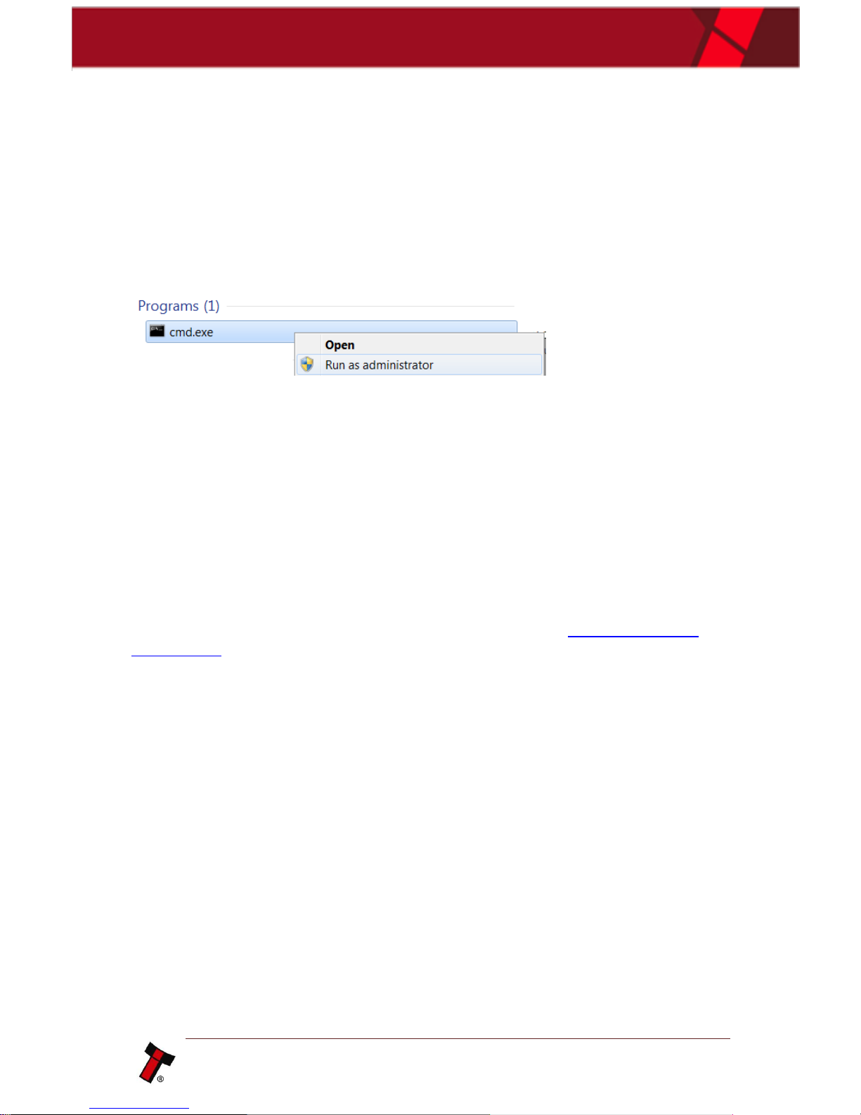
So you open an admin level command prompt
Once open type: shutdown.exe /r /o /f /t 0
/r Full shutdown and restart the computer.
/o Go to the advanced boot options menu and restart the computer.
Must be used with /r option.
/f Force running applications to close without forewarning users.
/t xxx Set the time-out period before shutdown to xxx seconds.
When the system restarts you can select "Disable Driver Signature Enforcement"
from the option screen and continue the installation as usual (3.1.2.1 Windows 7
Driver Install). Once the drivers have installed you can reboot your system to Enable
Driver Signature Enforcement.
Page 13
<< Back to Contents
Copyright © Innovative Technology Ltd 2017 Doc: User Manual DA3 GA02091
Version: 1.1
Page 12 of 42
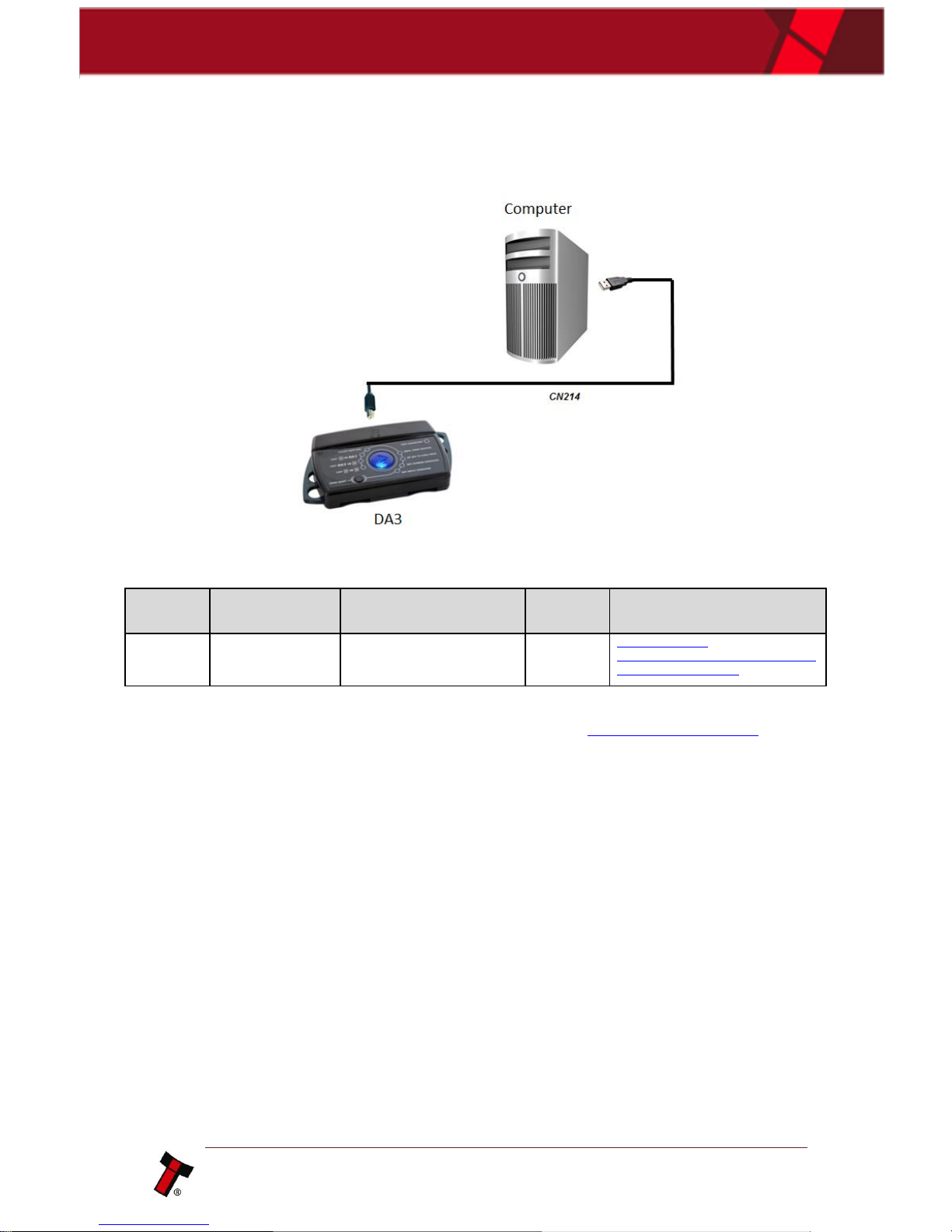
3.1.2 Connecting the DA3 to a Computer
Type
ITL Part
Number
Description
Quantity
Details
Cable
CN214
USB A to B Cable Assembly
1
http://innovativetechnology.com/shop/cables/usb-a-tob-cable-assembly-detail
This Cable is part of the DA3 Kit (Please refer to chapter 2.3.1 DA3 Kit Variants for
further information).
Page 14
<< Back to Contents
Copyright © Innovative Technology Ltd 2017 Doc: User Manual DA3 GA02091
Version: 1.1
Page 13 of 42
3.1.3 Connecting the DA3 in the Field for Update
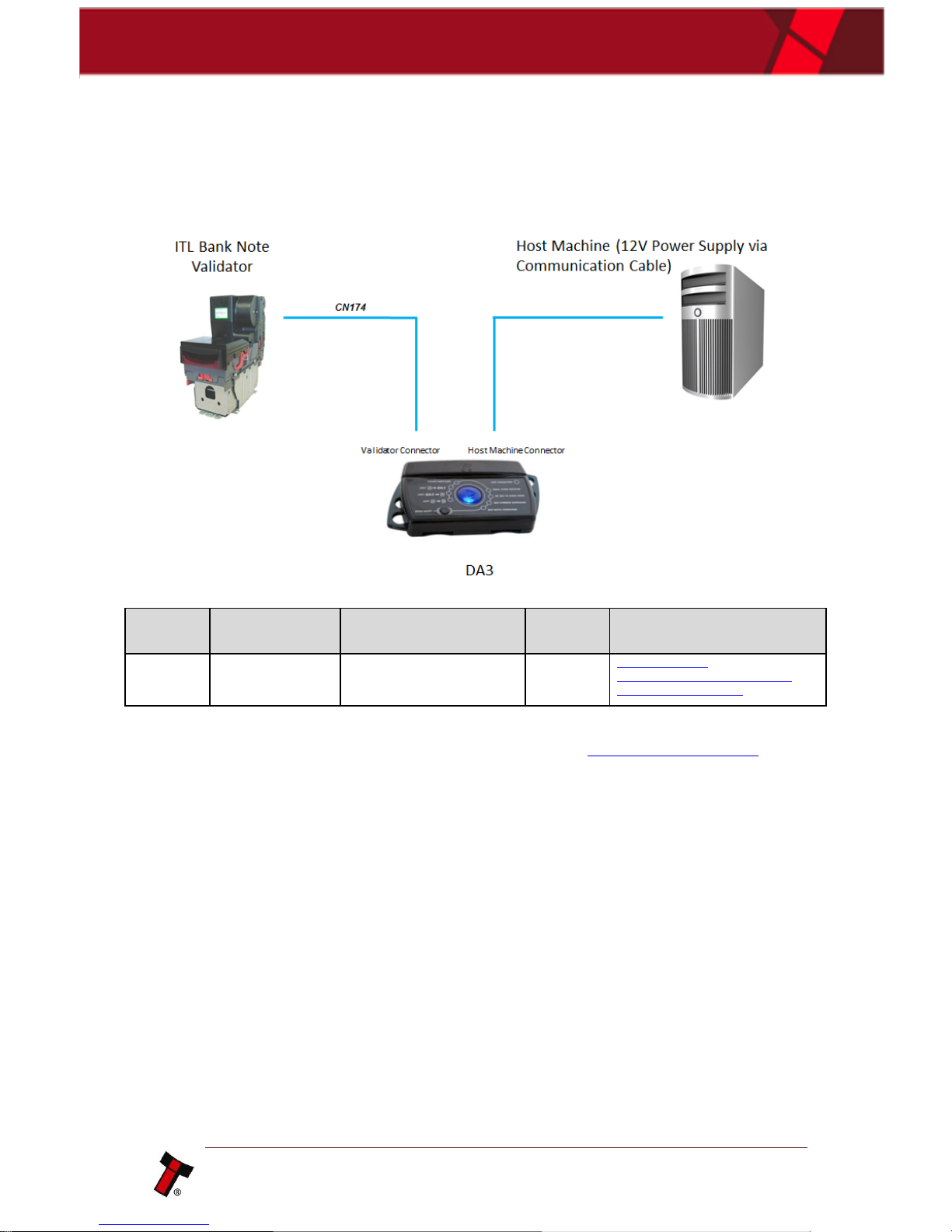
3.1.3.1 Option 1 – Power Supply via Host Machine
Type
ITL Part
Number
Description
Quantity
Details
Cable
CN174
NV9 / NV10 Ribbon Cable
1
http://innovativetechnology.com/shop/cables/nv9nv10-ribbon-cable-detail
This Cable is part of the DA3 Kit (Please refer to chapter 2.3.1 DA3 Kit Variants for
further information).
Host to Validator Cable
Page 15
<< Back to Contents
Copyright © Innovative Technology Ltd 2017 Doc: User Manual DA3 GA02091
Version: 1.1
Page 14 of 42
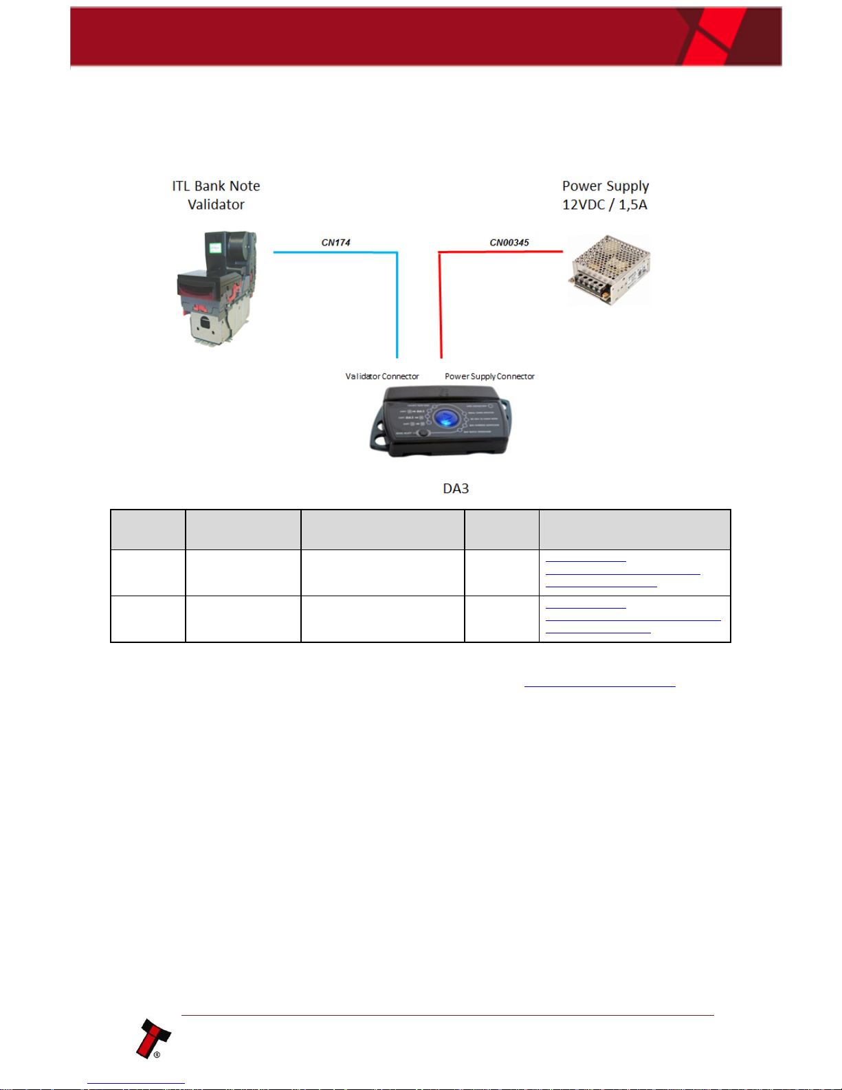
3.1.3.2 Option 2 – Power Supply via external Power Supply
Type
ITL Part
Number
Description
Quantity
Details
Cable
CN174
NV9 / NV10 Ribbon Cable
1
http://innovativetechnology.com/shop/cables/nv9nv10-ribbon-cable-detail
Cable
CN00345
DA3 / IF17 / IF18 Power Cable
1
http://innovativetechnology.com/shop/cables/da3-if17if18-power-cable-detail
The CN174 is part of the DA3 Kit (Please refer to chapter 2.3.1 DA3 Kit Variants for
further information) and the Cable CN00345 needs to be ordered separately.
Page 16
<< Back to Contents
Copyright © Innovative Technology Ltd 2017 Doc: User Manual DA3 GA02091
Version: 1.1
Page 15 of 42
4 SOFTWARE INSTALLATION AND CONFIGURATION
4.1 Software Overview
4.1.1 Device Programming System (DPS)
4.1.1.1 General Description
Device Programming System (DPS) is designed to configure a DA3 with the required
firmware and dataset variants for easy updates of ITL products in the field without
the need of a laptop or computer.
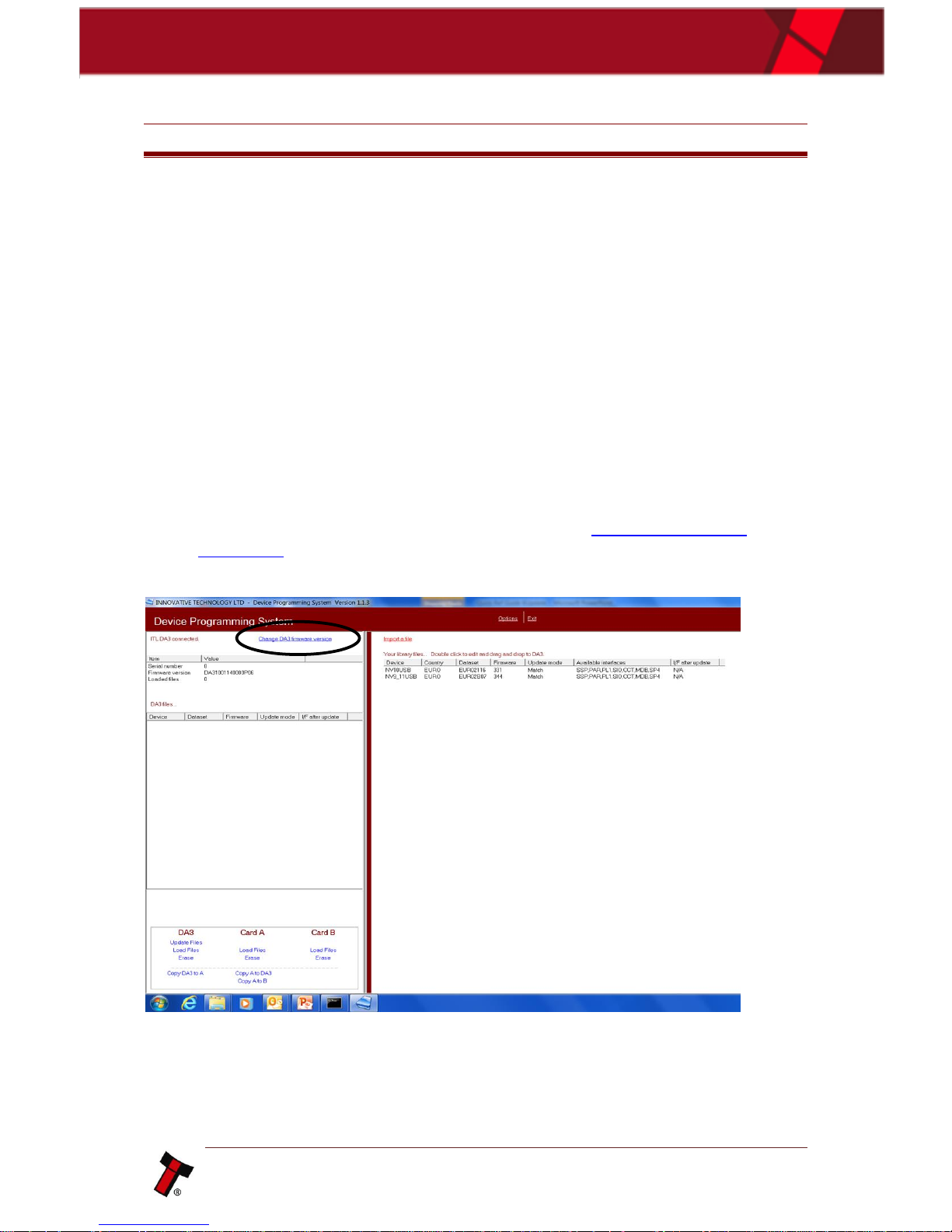
4.1.1.2 Firmware Update/Change on the DA3
• Connect the DA3 to your PC using a USB cable, and open DPS software. You
may need to install the DA3 driver. Please refer to chapter 3.1.1 Driver
Installation to proceed.
• Select ‘Change DA3 firmware version’ at top of screen.
• Select DA3 Standard firmware from your folder.
• Update DA3 firmware.
Page 17
<< Back to Contents
Copyright © Innovative Technology Ltd 2017 Doc: User Manual DA3 GA02091
Version: 1.1
Page 16 of 42
Caution!
Interrupting the download process can result in
the unit entering a non-functional state, once
the process has started it cannot be halted.
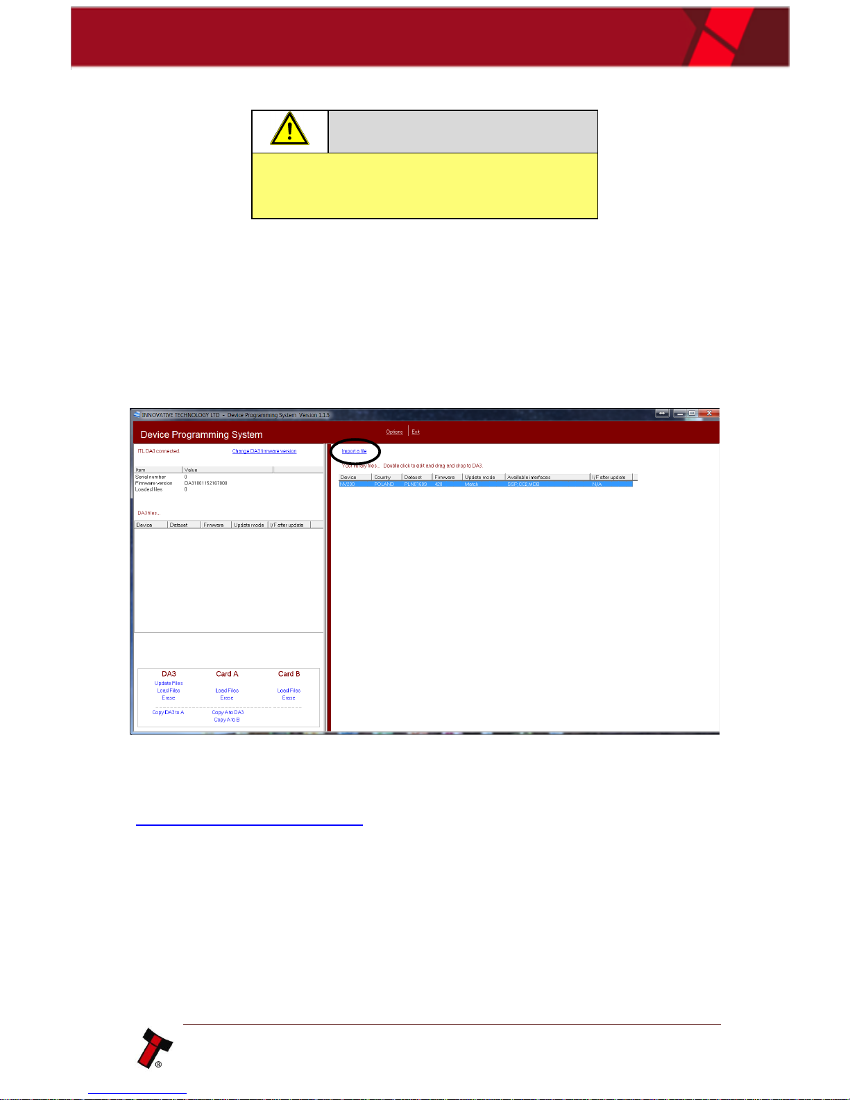
4.1.1.3 Adding datasets to the dataset library
The first step is to import a dataset into the program, to do this select ‘Import a file’,
this will open a new dialog box, now browse to the location of the dataset, and click
open.
Once a dataset has been loaded into the program it is loaded as a ‘match’ download,
if you wish to modify any of the settings you must switch it to an override download
(4.1.1.5 Tagging files for override).
Page 18
<< Back to Contents
Copyright © Innovative Technology Ltd 2017 Doc: User Manual DA3 GA02091
Version: 1.1
Page 17 of 42
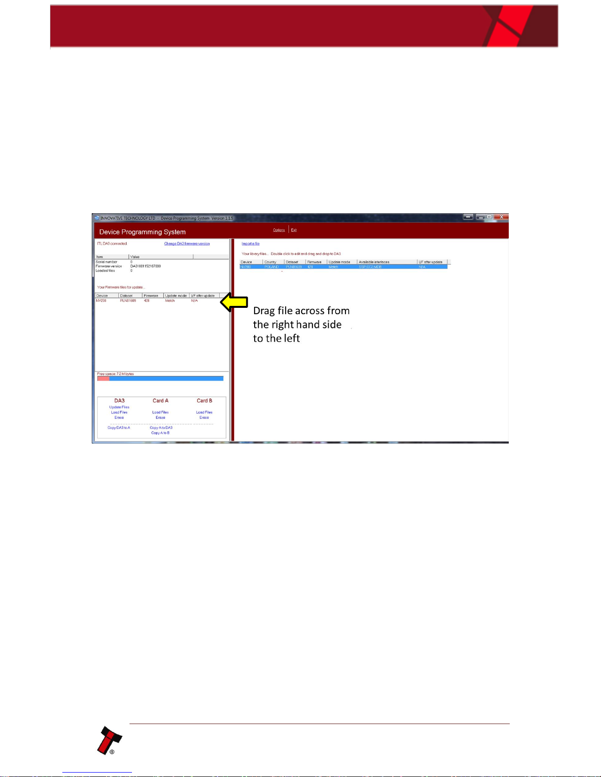
4.1.1.4 Storing files on the DA3
Once the files are ready to be copied onto the DA3 simply drag the file from the
right and drop on the left. This will prepare the file to be loaded onto the DA3. The
DA3 has 8mb of flash storage and can hold up to 20 datasets simultaneously
depending on files sizes. To complete the upload click ‘Update Files’ this will bring up
a message box explaining doing this will erase everything currently stored on the
DA3, to continue with the upload click ok.
Page 19
<< Back to Contents
Copyright © Innovative Technology Ltd 2017 Doc: User Manual DA3 GA02091
Version: 1.1
Page 18 of 42
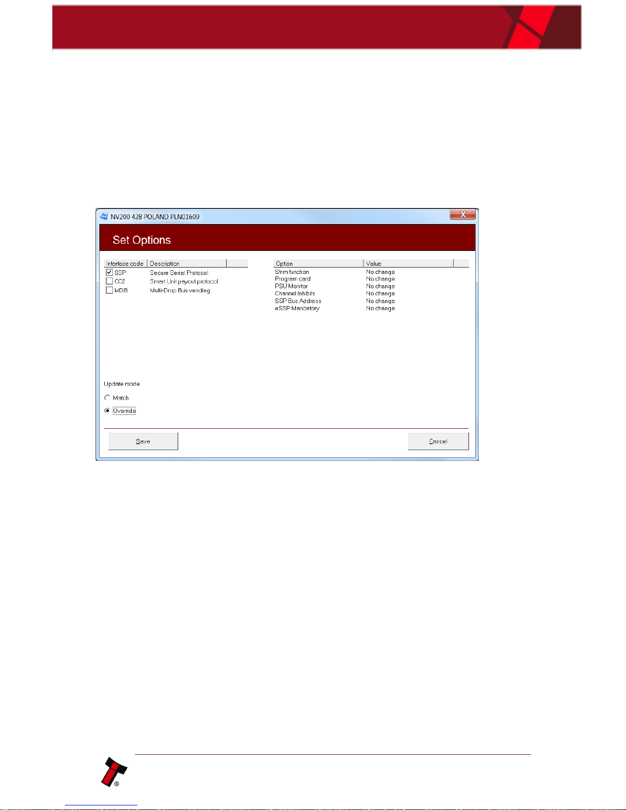
4.1.1.5 Tagging files for override
Double clicking on the dataset will open a ‘Set Options’ screen, from here you will be
able to modify all of the settings in the firmware. The SSP options are displayed
below; options for ccTalk® included setting the encryption, enabling/disabling DES,
setting the ccTalk® address. Once all the changes to the firmware are made, click
‘Save’ this will take you back to the landing page.
Page 20
<< Back to Contents
Copyright © Innovative Technology Ltd 2017 Doc: User Manual DA3 GA02091
Version: 1.1
Page 19 of 42
4.1.2 NV Memory Card Utilities
4.1.2.1 General Description
NV Card Utilities is designed to work with the DA3 handheld programmer and Data
Flash Cards; it allows the user to create update cards for the NV200 family of
products as well as log card functions for all units (excluding BV-series).
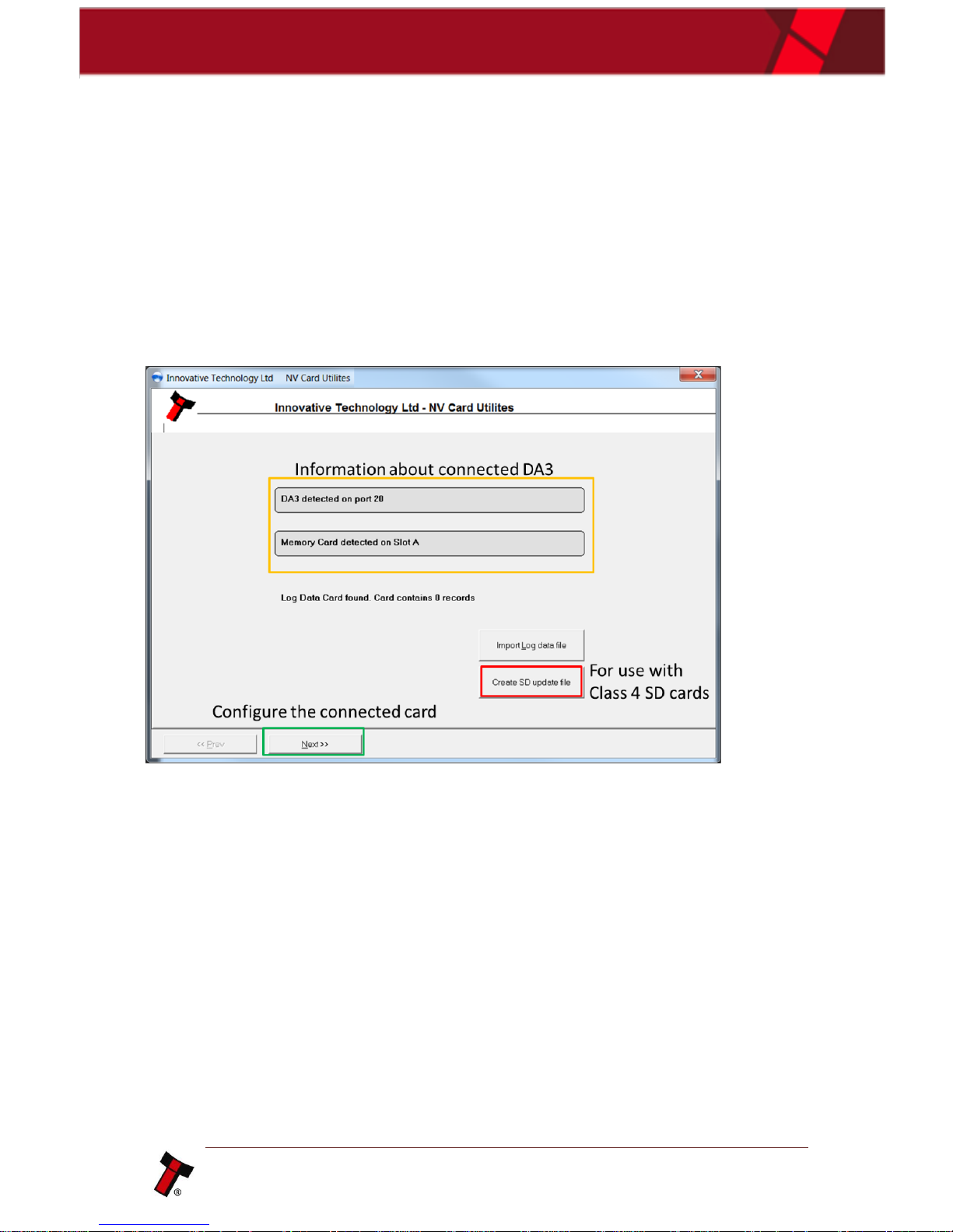
Once you have installed the program and connected your DA3 to the computer the
start screen will look like the screenshot below:
When you click next you will be prompted with another screen highlighting further
options for the user to select from. This additional options are for usage with the ITL
Data Flash Cards.
Page 21
<< Back to Contents
Copyright © Innovative Technology Ltd 2017 Doc: User Manual DA3 GA02091
Version: 1.1
Page 20 of 42
The following sections will briefly explain how to create custom Data Flash cards to
achieve several functions on the validator.
4.1.2.2 Format for log data
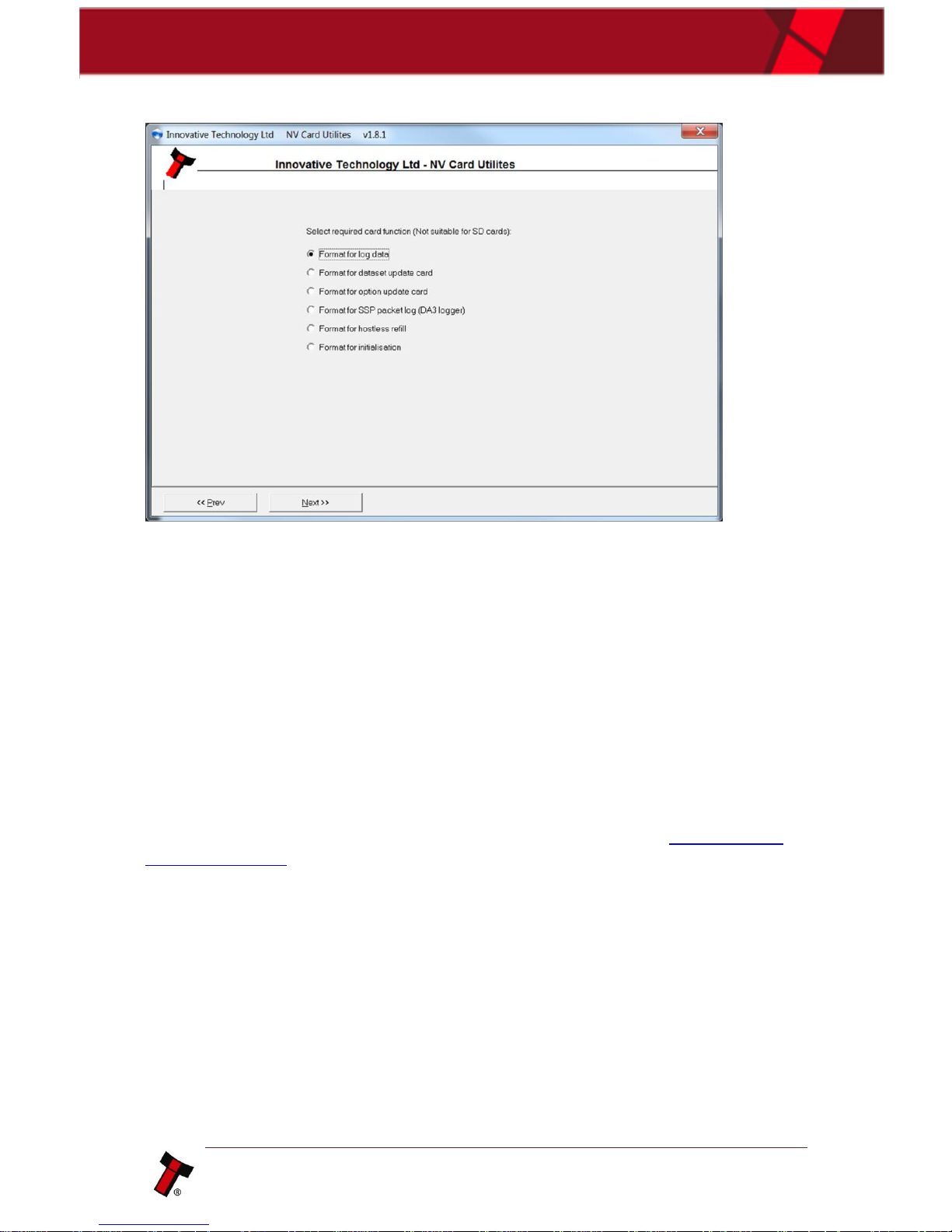
Formatting for log data allows any ITL validator (excluding BV-series) to collect up to
2 weeks’ worth of data; this can then be used for dataset improvements and
troubleshooting. To create a log data card, select the option at the screen then click
next, then on the next screen ‘Format for Log Data’. This can then be placed into the
slot at the front of the NV200 to begin logging, if you are using a different validator
you will also have to create a SSP packet logger please see section 4.1.2.5 Format
for SSP packet log.
Page 22
<< Back to Contents
Copyright © Innovative Technology Ltd 2017 Doc: User Manual DA3 GA02091
Version: 1.1
Page 21 of 42
4.1.2.3 Format for dataset update card (NV200 Range only)
This function allows you to load any NV200 dataset onto a Data Flash card for the
purposes of re-programming the validator.
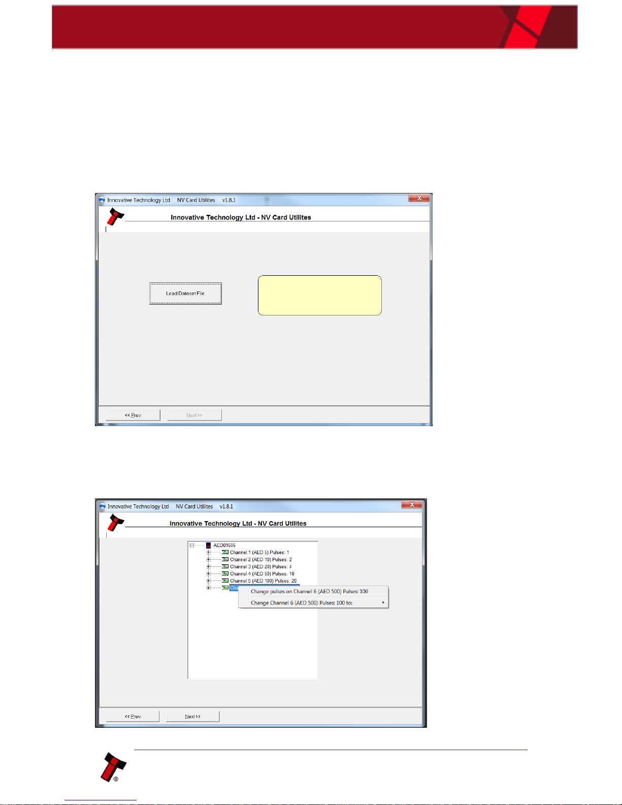
When you first click the option, you will be prompted with the below screen, you
would need to select your dataset (usually located within the downloads folder) and
then click next.
Once the dataset has been loaded it is possible to configure it to fulfill your
requirements, on the first screen there is the possibility to change the pulses for the
channels. This can be changed should the host machine be expecting specific values.
Page 23
<< Back to Contents
Copyright © Innovative Technology Ltd 2017 Doc: User Manual DA3 GA02091
Version: 1.1
Page 22 of 42
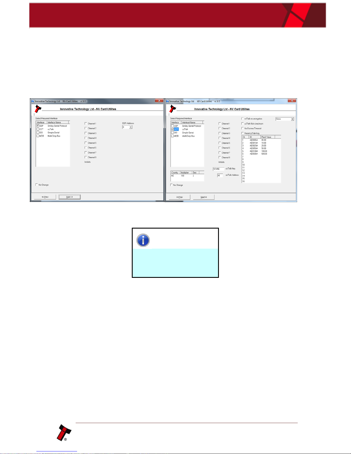
The next screen will allow you to customize the interface and channel inhibits. To
change the interface, simply check the relevant box. Similarly, to inhibit a channel
tick the corresponding box.
On the left is the options available with SSP selected, and on the right, are the
options available through selecting the ccTalk® interface.
Information
If you want to keep the
current settings on the unit,
select no change.
Page 24
<< Back to Contents
Copyright © Innovative Technology Ltd 2017 Doc: User Manual DA3 GA02091
Version: 1.1
Page 23 of 42
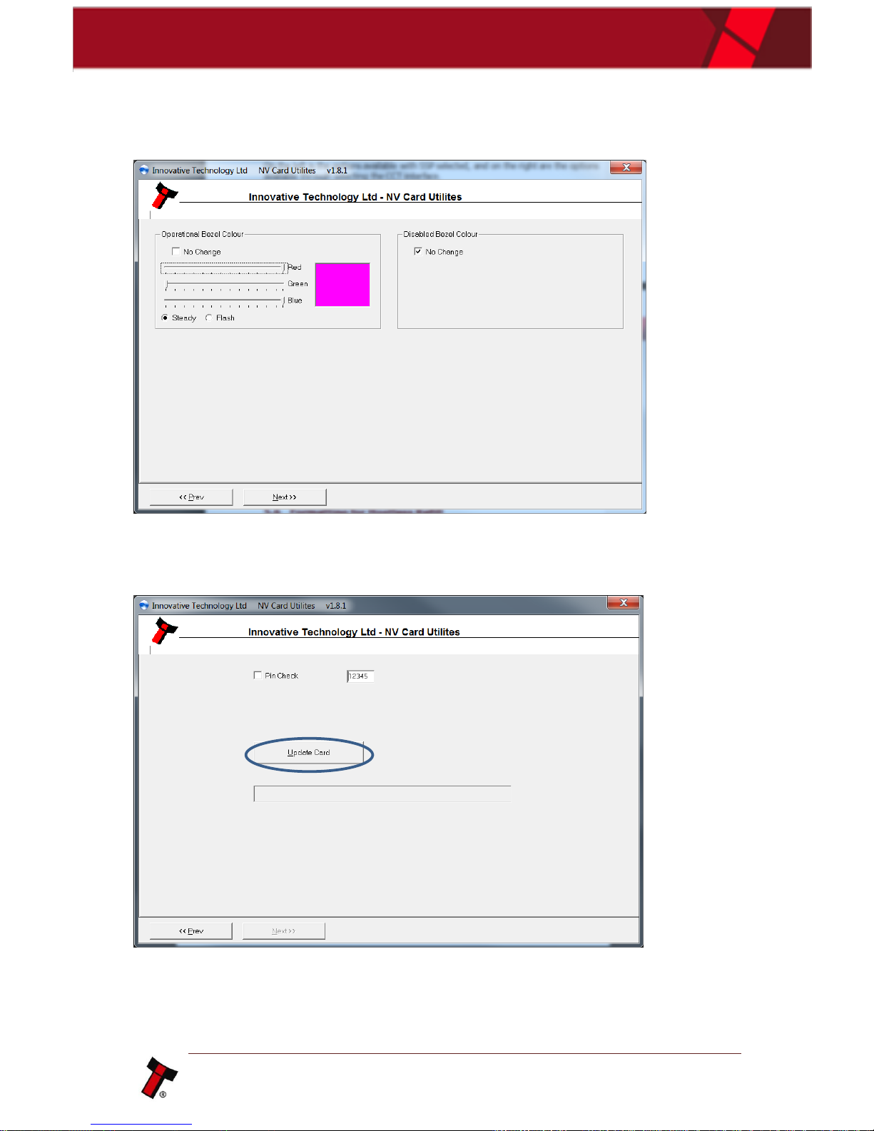
The next screen allows you to get modify the bezel colors during operation and
whilst disabled. The color can be selected using an RGB slider as shown below.
As soon as the required Bezel options are selected, press next to proceed to the next
screen, here you will be able to load the update onto the Data Flash card.
Click on ‘Update card’ and the file will be loaded onto the Data Flash card.
Page 25
<< Back to Contents
Copyright © Innovative Technology Ltd 2017 Doc: User Manual DA3 GA02091
Version: 1.1
Page 24 of 42
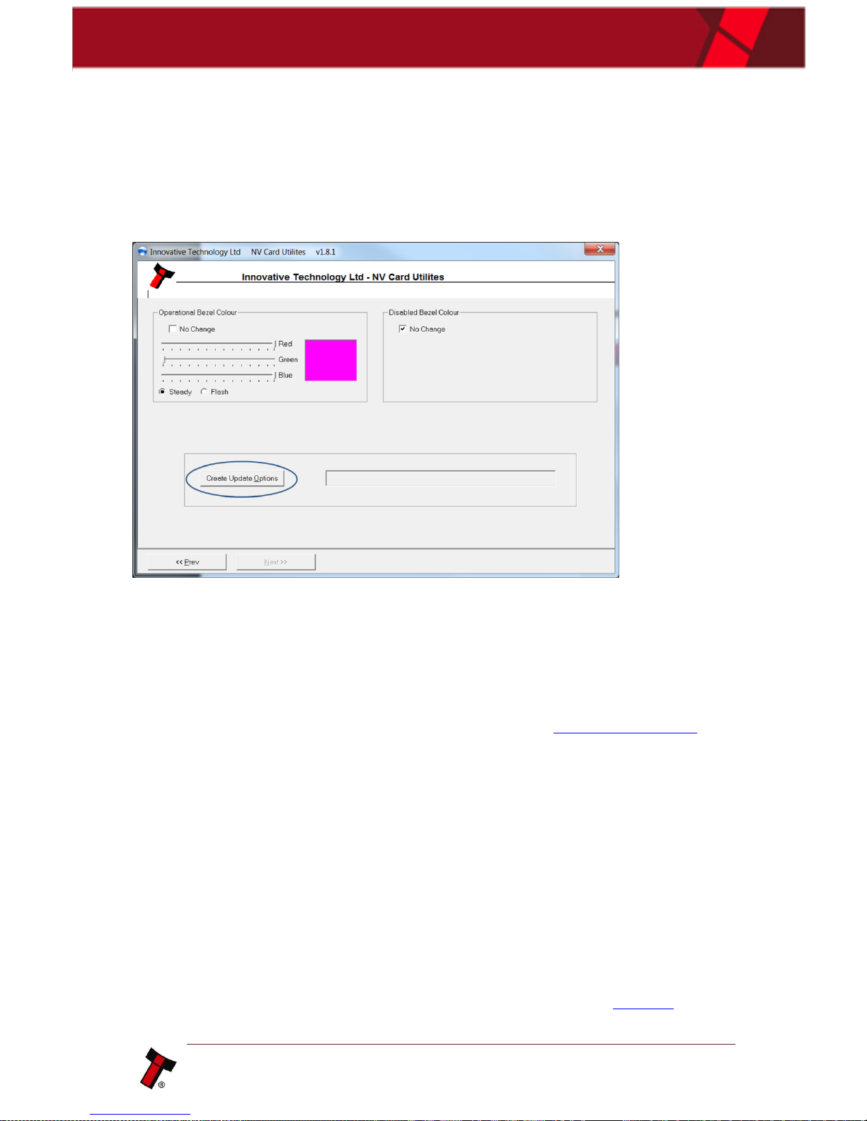
4.1.2.4 Format for option update card (NV200 Range only)
Formatting for option update allows you to modify the bezel colour of the NV200,
simply select the RGB colour using the sliders and select ‘Create Update Options’.
Once this has been clicked it will format and upload the changes onto the ITL Data
Flash card.
4.1.2.5 Format for SSP packet log
Formatting for SSP packet logging is to be used in conjunction with a standard log
card in a DA3 to capture all the transmitted and received packets between any of
ITL’s validators (excluding BV-series).and the host machine. A more detailed
instruction on how to do this can be obtained from chapter 5.1.10 Data Logging.
4.1.2.6 Format for Hostless Refill (NV200 Range only)
Formatting for Hostless Refill is designed to allow a customer to fill a Payout module
without connecting data lines to the host machine, this is useful if the Payout needs
to be loaded in a secure location where only power is available or balancing real
note values and machine counters.
4.1.2.7 Format for initialisation (NV200 Range only)
This feature allows the user to re-initialise the NV200 validator. To perform the
initialisation you will also need the corresponding calibration paper (LB00149).
Page 26

<< Back to Contents
Copyright © Innovative Technology Ltd 2017 Doc: User Manual DA3 GA02091
Version: 1.1
Page 25 of 42
4.1.2.8 Upload Log Data
• Open NV card utilities, connect a DA3 via a USB cable and put the Log data
card in Slot A. Select ‘Next’.
• Select Upload Log data and hit ‘Next’.
• Select Upload Records. NV Utilities extracts the data and displays a list of
events in a new window.
• Select ‘Export as raw data’ button.
• Select the location of where you want the file to be saved. It will be saved as
an xxxx.NRC file.
• This file can be zipped and sent to [email protected] for
analysis.
Page 27

<< Back to Contents
Copyright © Innovative Technology Ltd 2017 Doc: User Manual DA3 GA02091
Version: 1.1
Page 26 of 42
5 OPERATION AND SETUP
5.1 Standard Firmware
5.1.1 General Description
The standard firmware allows dataset and firmware files for different validator
models to be stored on the DA3.
Once programmed the user can update or override existing software as well as test
the functionality of the validator, away from the host machine.
5.1.2 BNV Match Download
This mode will update the connected BNV with the latest version of dataset and
firmware currently programmed into the BNV. All custom settings (pulses, special
interface etc.) will remain the same. Tagging files has no effect when the DA3 is
used in this mode. For this function to operate, the versions of firmware and dataset
stored within the DA3 memory must be later than that stored within the connected
validator.
• Set the BNV to SSP mode as described in the BNV product manual.
Depending on the BNV model, this will be either by setting the dipswitches as
shown on the product label, or by pressing the configuration button
• Connect the BNV to the DA3 as described in chapter 3.1.3 Connecting the
DA3 in the field for Update and apply power either from the host machine or
from a separate 12V power supply.
• Press the Mode Select button repeatedly until the blue BNV MATCH
DOWNLOAD LED is illuminated. The RUN button will pulse green to indicate
that this function is available.
• Press the Centre Run Button.
• The centre RUN button will change colour to pulsing blue, and the Mode
Indicator LEDs will rotate back and forth as communication is established and
the current BNV settings are determined. The DATA CONNECTION LED with
flicker as data is transferred to and from the DA3. If there are no matching
firmware or dataset files stored on the DA3, the centre RUN button will
change colour to pulsing red and the blue BNV MATCH DOWNLOAD LED will
flash a code as described in chapter 6.1 LED Error Flash Codes.
• If all the files are available on the DA3, the Mode Indicator LED’s will rotate in
an anti-clockwise direction while the firmware is updated.
• Once the firmware update is complete (a quick Reset will be performed) and
the Mode Indicator LED’s will rotate in a clockwise direction as the dataset is
updated.
• When the firmware and dataset are successfully updated, the centre RUN
button will change to a pulsing green light and the BNV will reset.
Page 28

<< Back to Contents
Copyright © Innovative Technology Ltd 2017 Doc: User Manual DA3 GA02091
Version: 1.1
Page 27 of 42
BNV Override Download
This mode will overwrite the BNV with pre-selected (Tagged) firmware and dataset
files. For this function to operate, the DA3 must have dataset and firmware files
tagged for the attached BNV model. See Chapter 4.1.1.5 Tagging files for override
for details on tagging files.
• Set the BNV to SSP mode as described in the BNV product manual.
Depending on the BNV model, this will be either by setting the dipswitches as
shown on the product label, or by pressing a download Configuration button.
• Connect the BNV to the DA3 as described in chapter 3.1.3 Connecting the
DA3 in the field for Update, and apply power either from the host machine or
from a separate power supply.
• Press the Mode Select button repeatedly until the blue BNV Override
DOWNLOAD LED is illuminated. The RUN button will pulse green to indicate
that this function is available.
• Press the Centre Run Button.
• The Centre RUN button will change colour to pulsing blue, and the Mode
Indicator LEDs will rotate back and forth as communication is established and
the current BNV settings are determined. The DATA CONNECTION LED with
flicker as data is transferred to and from the DA3. If there are no matching
firmware or dataset files stored on the DA3, the centre RUN button will
change colour to pulsing red and the blue BNV MATCH DOWNLOAD LED will
flash a code as described in chapter 6.1 LED Error Flash Codes.
• If all the files are available on the DA3, the Mode Indicator LED’s will rotate in
an anti-clockwise direction while the firmware is updated.
• Once the firmware update is complete, the Mode Indicator LED’s will rotate in
a clockwise direction as the dataset is updated.
• When the firmware and dataset are successfully updated, the centre RUN
button will change to a pulsing green light and the BNV will reset.
Page 29

<< Back to Contents
Copyright © Innovative Technology Ltd 2017 Doc: User Manual DA3 GA02091
Version: 1.1
Page 28 of 42
5.1.3 Set BNV to check mode
This function enables the validator to accept notes so that testing can take place
outside of the host machine.
• Set the BNV to SSP mode as described in the BNV product manual.
Depending on the BNV model, this will be either by setting the dipswitches as
shown on the product label, or by pressing a download Configuration button.
• Connect the BNV to the DA3 as described in chapter 3.1.3 Connecting the
DA3 in the field for Update, and apply power either from the host machine or
from a separate power supply.
• Press the Mode Select button repeatedly until the blue SET BNV TO CHECK
MODE LED is illuminated. The RUN button will pulse green to indicate that
this function is available.
• Press the Centre RUN button.
• The Centre RUN button will change colour to pulsing blue, and the DATA
CONNECTION LED with flash as data is transferred to and from the DA3. If
communications cannot be established the Centre RUN button will change
colour to pulsing red, and the blue SET BNV TO CHECK MODE LED will flash a
code as described in chapter 6.1 LED Error Flash Codes.
• When notes are inserted and accepted, the Mode Indicator LED will switch off
a number of times according to which channel the note has been credited.
For example, if a note from channel 3 has been inserted, the Mode Indicator
LED will switch off and back on again 3 times.
5.1.4 Serial Comm Monitor
This function is not yet implemented.
5.1.5 Collect Note Data
This function is not yet implemented.
Page 30
<< Back to Contents
Copyright © Innovative Technology Ltd 2017 Doc: User Manual DA3 GA02091
Version: 1.1
Page 29 of 42
5.1.6 Copy A to DA3
This function copies the contents of the memory card in slot A to the internal
memory of the DA3.
Caution!
All files stored in the DA3 memory
will be overwritten.
• Press the Mode Select button repeatedly until the blue Copy A DA3 LED is
illuminated. The RUN button will pulse green to indicate that this function is
available.
• Press the RUN button – the RUN button will change colour from pulsing green
to solid blue, and the MODE SELECT button light will switch off.
• Press the RUN button again within 3 seconds to confirm.
o If the RUN button is not pressed a second time within 3 seconds, the
colour of the button will revert to green, and the MODE SELECT button
will re-light blue.
o If there is no Data Flash card in slot A, or the Data Flash Card is blank,
the Centre RUN button will pulse red, and the blue Copy A DA3 LED
will flash a code as described in chapter 6.1 LED Error Flash Codes.
• The Mode Indicator LED’s will rotate in an anti-clockwise direction while the
entire contents of the memory card in slot A are be copied to the internal
memory of the DA3.
• When the copy procedure is completed, the Centre RUN button will pulse
green.
5.1.7 Copy DA3 to A
This function copies the contents of the internal memory on the DA3 to the Data
Flash card.
Caution!
All files stored on the Data Flash
will be overwritten.
• Press the Mode Select button repeatedly until the blue Copy DA3 A LED is
illuminated. The RUN button will pulse green to indicate that this function is
available.
• Press the RUN button – the RUN button will change colour from pulsing green
to solid blue, and the MODE SELECT button light will switch off.
Page 31
<< Back to Contents
Copyright © Innovative Technology Ltd 2017 Doc: User Manual DA3 GA02091
Version: 1.1
Page 30 of 42
• Press the RUN button again within 3 seconds to confirm.
o If the RUN button is not pressed a second time within 3 seconds, the
colour of the button will revert to green, and the MODE SELECT button
will re-light blue.
o If the DA3 is blank or if there is no Data Flash card in slot A, the
Centre RUN button will pulse red, and the blue Copy DA3 A LED will
flash a code as described in chapter 6.1 LED Error Flash Codes.
• The Mode Indicator LED’s will rotate in an anti-clockwise direction while the
entire contents of the internal memory of the DA3 are be copied to the
memory card in slot A.
• When the copy procedure is complete, the Centre RUN button will pulse
green.
5.1.8 Copy A to B
This function copies the contents of the Data Flash card in slot A to the Data Flash
card in slot B.
Caution!
All files stored on the Data Flash in
Slot B will be overwritten.
• Press the Mode Select button repeatedly until the blue Copy A B LED is
illuminated. The RUN button will pulse green to indicate that this function is
available.
• Press the RUN button – the RUN button will change colour from pulsing green
to solid blue, and the MODE SELECT button light will switch off.
• Press the RUN button again within 3 seconds to confirm.
o If the RUN button is not pressed a second time within 3 seconds, the
colour of the button will revert to green, and the MODE SELECT button
will re-light blue.
o If there is no Data Flash card in slot A, or the Data Flash Card is blank,
the Centre RUN button will pulse red, and the blue Copy A B LED will
flash a code as described in chapter 6.1 LED Error Flash Codes.
• The Mode Indicator LED’s will rotate in an anti-clockwise direction while the
entire contents of the Data Flash card in slot A are be copied to the memory
card in slot B.
• When the copy procedure is complete, the Centre RUN button will pulse
green.
Page 32
<< Back to Contents
Copyright © Innovative Technology Ltd 2017 Doc: User Manual DA3 GA02091
Version: 1.1
Page 31 of 42
5.1.9 Data Logging
5.1.9.1 General Description
The DA3 can also be used as a data logging device, utilising the two card slots on
the unit. This allows the capturing of performance data and also helps with
diagnosing any issues seen in the field.
5.1.9.2 Requirements
• Latest Validator Manager version
• A DA3 from week 17 2013 or later with latest firmware version
• Latest NV Cards Utilities version
• ITL Bank Note Validator with a latest Dataset and Firmware
5.1.9.3 Setup
• Format a Data Flash card as an SSP Packet Data Log card using NV Cards
Utilities (as described in chapter 4.1.2 NV Memory Card Utilities).
• The next step is to format a data flash card as a Log Data card (as described
in chapter 4.1.2 NV Memory Card Utilities).
• Open the Validator Manager and connect to the validator that you want to
collect data from. Go to the Options tab and change the option “Enable Data
Monitor” from Off to On. Hit the “Apply Changes” button. You get an ‘Options
Set Successfully’ message and the validator resets.
Information
All software from Innovative Technology
Ltd is free of charge and can be
downloaded from the website
www.innovativetechnology.com/support/securedownload
once registered and logged in.
Page 33

<< Back to Contents
Copyright © Innovative Technology Ltd 2017 Doc: User Manual DA3 GA02091
Version: 1.1
Page 32 of 42
5.1.9.4 Collecting Data
• Connect the DA3 in series to the Validator.
• Put the SSP Packet Data card in slot A and the Log Data card in slot B
• The DA3 automatically goes into data collection mode, saving log data to the
Log Data card in Slot B and SSP Packet Data to the SSP Packet card. The
Centre RUN button lights Blue and the Mode LED’s start a sequence clockwise
and anticlockwise, again in blue.
• Run the Validator with the Host Software (normal operation).
• Stop the DA3 recording by pressing the Centre RUN button. It now changes
to green. The recording MUST be stopped by pressing this button before you
remove the card or else the data on the card may get corrupted.
• Remove the Log Data Card from slot B. This contains all the required events
and data.
• The DA3 can be left connected in series in this mode and will gather data
continuously. When the card’s memory is full it will overwrite the earliest
records and keep recording. The engineer can visit the machine and swap
cards as required.
5.1.9.5 Extract the Data
To extract the Data, proceed as descripted in chapter 4.1.2.8 Upload Log Data.
Page 34
<< Back to Contents
Copyright © Innovative Technology Ltd 2017 Doc: User Manual DA3 GA02091
Version: 1.1
Page 33 of 42
5.2 SMART Update Firmware
5.2.1 General Description
The SMART Update Tool provides all applicable datasets for a given currency across
our product range, allowing multiple units in the field to be easily updated with a
single file.
5.2.2 Requirements
• 1 x DA3 handheld programmer
• Latest Custom DA3 SMART Update firmware
• UpdateV2.bin file - download it from the ITL Website
• Min 2Gb SD Card, Class 4. Sandisk, Kingston Technology, Transcend have all
been tested. NB: Class 10 cards are not supported. Format must be FAT32.
• Latest Custom DPS version
Information
All software from Innovative Technology
Ltd is free of charge and can be
downloaded from the website
www.innovativetechnology.com/support/securedownload
once registered and logged in.
Page 35
<< Back to Contents
Copyright © Innovative Technology Ltd 2017 Doc: User Manual DA3 GA02091
Version: 1.1
Page 34 of 42
5.2.3 Setup
• Log in to the ITL website software support section www.innovative-
technology.com/support.
• Download the required SMART package which contains: UpdateV2.bin file
location. (Save to a folder on your PC and extract files)
• Place SD card in PC card slot and copy UpdateV2.bin file to the card. The file
is big (200Mb approx), so this takes a few minutes.
• Connect the DA3 to your PC using a USB cable, and open DPS software. You
may need to install the DA3 driver. Please refer to chapter 3.1.2 Driver
Installation to proceed.
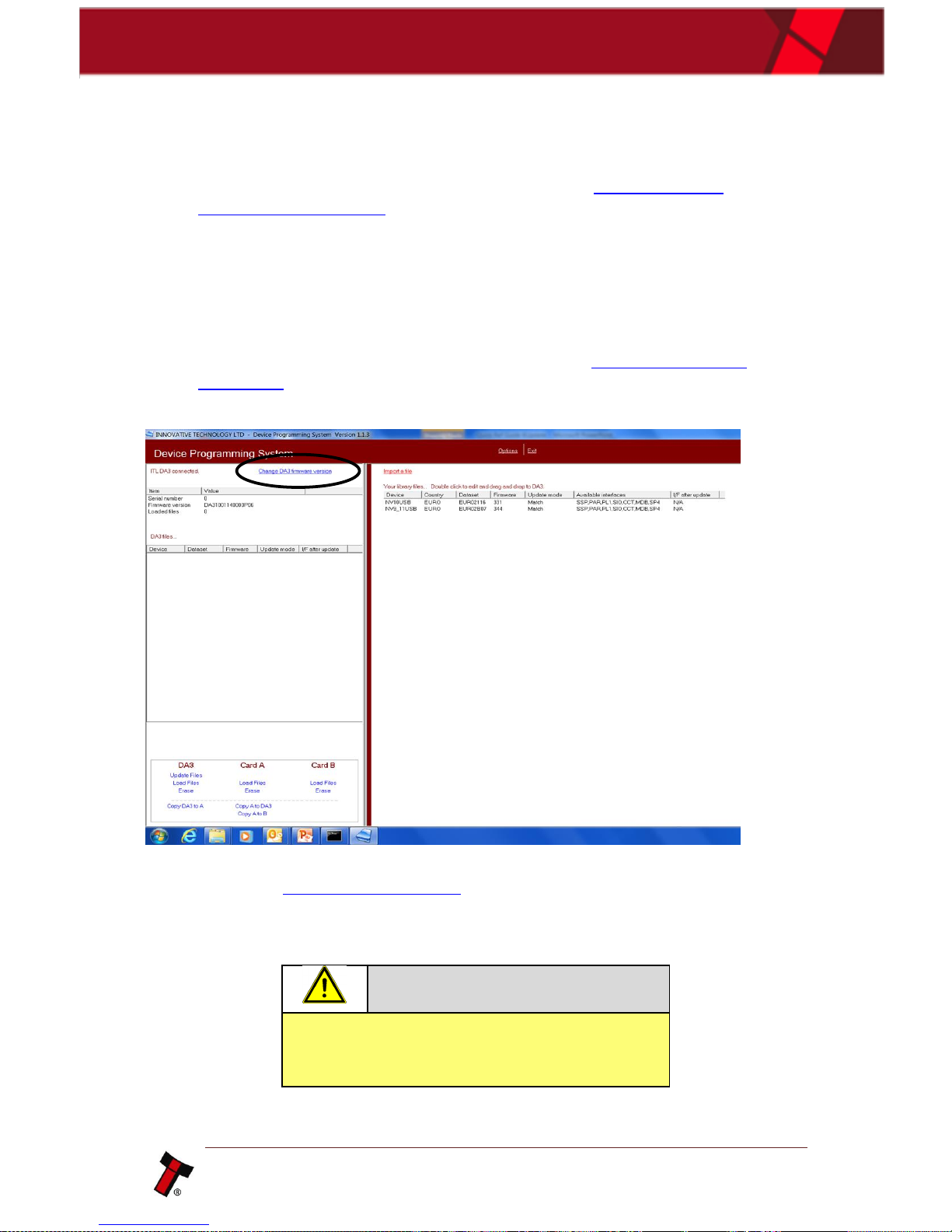
• Select ‘Change DA3 firmware version’ at top of screen.
• Select DA3 SMART Update firmware from your folder (for further details refer
to chapter 9.3 Firmware Identifier).
• Update DA3 firmware.
Caution!
Interrupting the download process can result in
the unit entering a non-functional state, once
the process has started it cannot be halted.
• Disconnect DA3 from PC.
Page 36

<< Back to Contents
Copyright © Innovative Technology Ltd 2017 Doc: User Manual DA3 GA02091
Version: 1.1
Page 35 of 42
5.2.4 Update Procedure
• Insert SD card with the UpdateV2.bin file loaded into Slot A on the DA3.
• Connect the DA3 to the validator using the ribbon cable and 16-way
connector and power it from the host ribbon cable.
• Allow the validator to power up and ensure it is in SSP mode (9.2 Switching
ITL devices to Programming Mode (SSP)).
• Press the blue button on the DA3. The button turns green when the dataset
has been updated, and the validator resets.
• Disconnect the DA3, reconnect the validator to the host and power up the
validator.
Page 37
<< Back to Contents
Copyright © Innovative Technology Ltd 2017 Doc: User Manual DA3 GA02091
Version: 1.1
Page 36 of 42
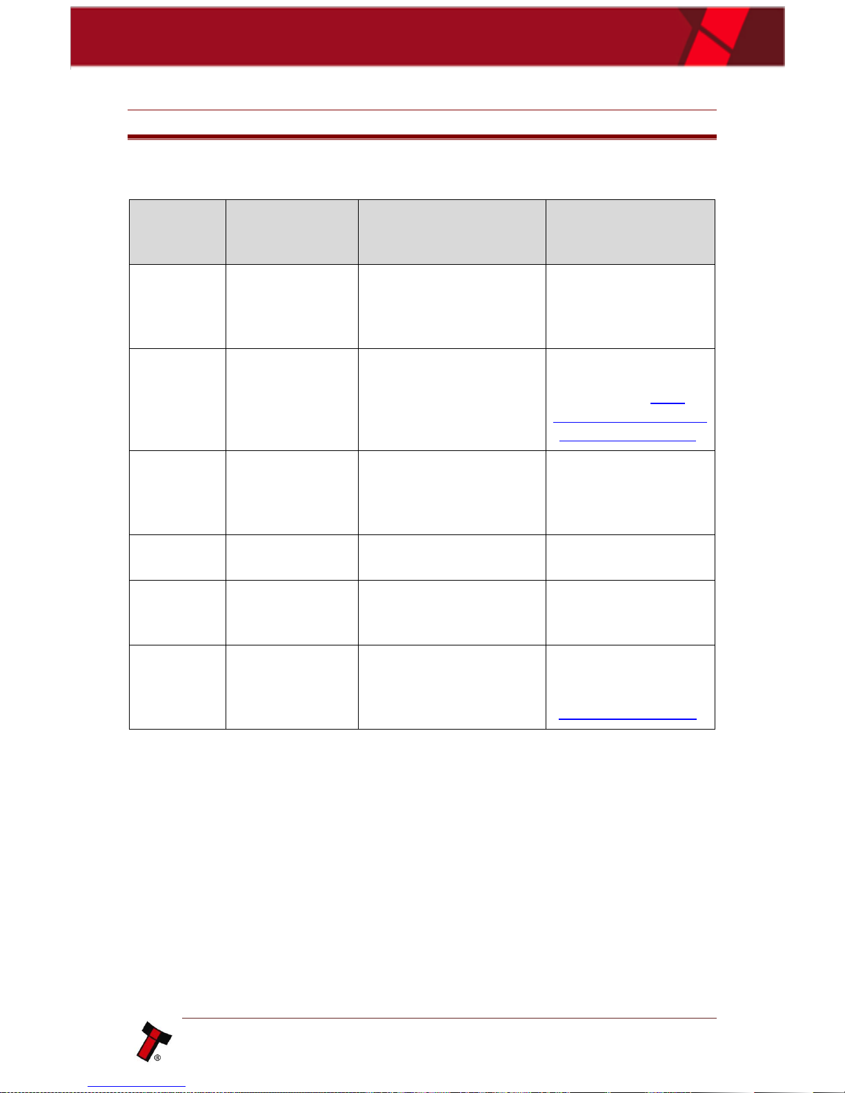
6 FIRST LEVEL SUPPORT
6.1 LED Error Flash Codes
Number
of LONG
flashes
Number of
SHORT flashes
Indicated Status /
Error
Action
1
1
Incompatible Dataset
Check if the dataset
on the DA3 match the
connected Validator
type.
1
2
No validator connection
found
Check if the wiring is
correct. Please refer
to chapter 3.1.3
Connecting the DA3 in
the Field for Update.
1
3
No valid download files
found
Check if the dataset
on the DA3 match the
connected Validator
type.
1 4 Download fail
Check if correct and
latest FW is in use.
1 5 Memory card fail
Check if the inserted
Card is suitable for
the DA3.
1
8
Heap Fail (Data Logging
Problem)
Check if the correct
setup is made as
described in chapter
5.1.9 Data Logging.
Page 38
<< Back to Contents
Copyright © Innovative Technology Ltd 2017 Doc: User Manual DA3 GA02091
Version: 1.1
Page 37 of 42
7 TECHNICAL DATA
7.1 Environmental Requirements
Environment
Minimum
Maximum
Temperature
+3°C
+50°C
Humidity
5%
95% Non-condensing
7.2 Power Requirements
7.2.1 Supply Voltages
When programming the DA3 using the DPS software, power is taken from the USB
bus; no external power supply is required.
When programming validators, or using the DA3 card copy functions, power must be
applied via the host machine or from a separate 12V DC, 1500mA power supply.
7.3 Dimensions
Page 39

<< Back to Contents
Copyright © Innovative Technology Ltd 2017 Doc: User Manual DA3 GA02091
Version: 1.1
Page 38 of 42
8 COMPLIANCES AND APPROVALS
8.1 EC Declaration of Conformity
• RoHS
• EN Directives
• UL
• REACH
• WEEE
Please contact [email protected] for further information. Detailed
information is available on request.
Page 40
<< Back to Contents
Copyright © Innovative Technology Ltd 2017 Doc: User Manual DA3 GA02091
Version: 1.1
Page 39 of 42
9 APPENDIX
9.1 Cable Drawings
9.1.1 CN00214 – USB A to B cable assembly
Page 41
<< Back to Contents
Copyright © Innovative Technology Ltd 2017 Doc: User Manual DA3 GA02091
Version: 1.1
Page 40 of 42
9.1.2 CN174 – Ribbon Cable
Page 42
<< Back to Contents
Copyright © Innovative Technology Ltd 2017 Doc: User Manual DA3 GA02091
Version: 1.1
Page 41 of 42
9.1.3 CN00345 - DA3 Power Cable
Page 43
<< Back to Contents
Copyright © Innovative Technology Ltd 2017 Doc: User Manual DA3 GA02091
Version: 1.1
Page 42 of 42
9.2 Switching ITL devices to Programming Mode (SSP)
Please refer to the individual product manual, how to switch the ITL device to the
Programming Mode (SSP).
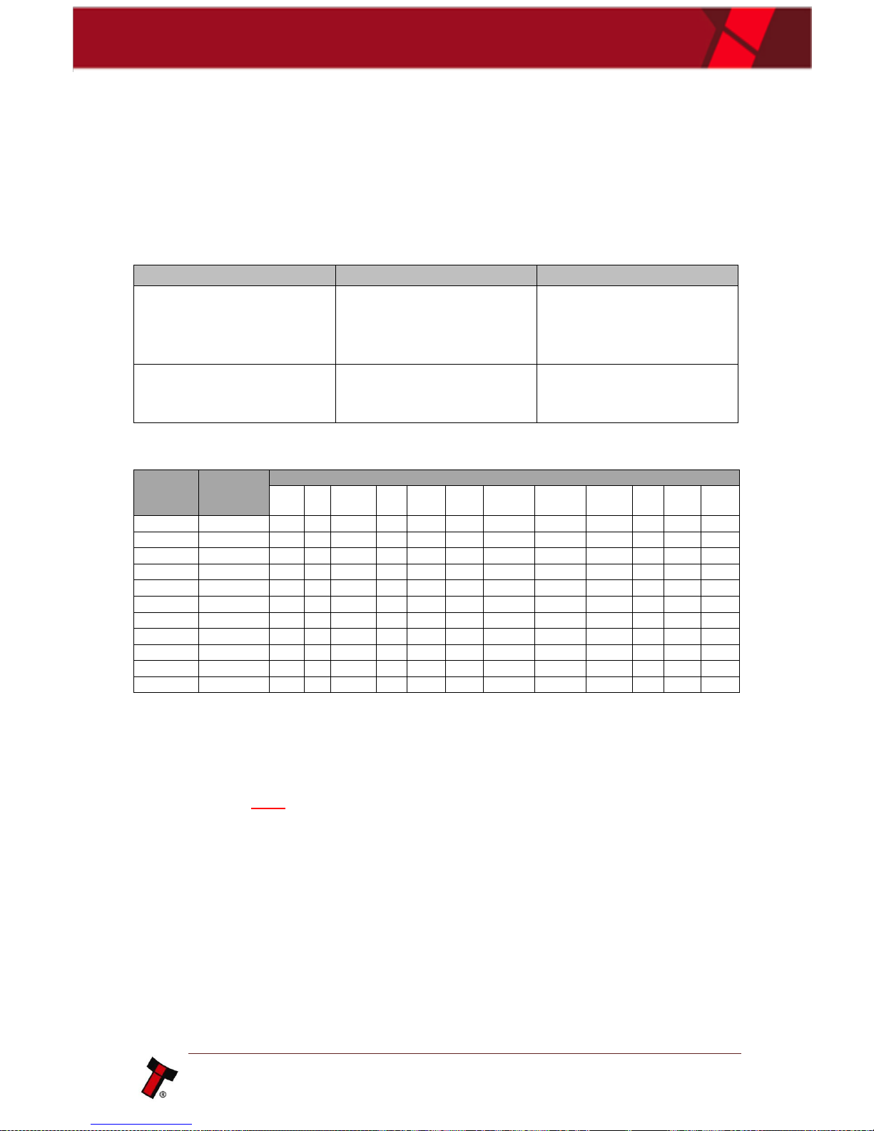
The most ITL Products have a Configuration Button with the following functionality:
Action
Power Status
Function
Press and hold (more
than 2 seconds) until the
bezel illuminates, then
release
Powered ON
Switch the validator
interface
Press twice (within half a
second)
Powered ON
Shows current interface
type (see
flash count table below)
Flashes
Interface
Interface Settings
CCT
plain
CCt
8bit
No
Escrow
Timeout
DES
Low
Power
High
Speed
Pulse
High
Pulse Low
Pulse
per £
SIO
start
dis
Credit
Hold
Binary
1
SSP
2
Pulse
ms/10
ms/10
value 3
3
MDB
4
IF30
5
IF31
6
ccTalk®
1 2 3 4 7
SIO
3 1 2 8
Parallel
2 1 9
SP4
ms/10
ms/10
value 3 10
NS
11
IF32
1
9.3 Firmware Identifier
DA31001210000SMT.vps – SMART Update Firmware
DA31001210000003.vps – Standard Firmware
 Loading...