

Page 1
Specifications are subject to change without notice. No liability accepted for errors or omissions.
1
Model Codes: SR250A/SR500A/SR750A
SR250D/SR500D/SR750D
SR250L/SR500L/SR750L
SR250P
SR250M
= Standard
= Standard with alarms
= ‘D’ version with extra output alarm (LV versions only
for SR500L and S750L)
= ‘D’ version with built-in output diode (24V & above)
= for use with OVP input protection units
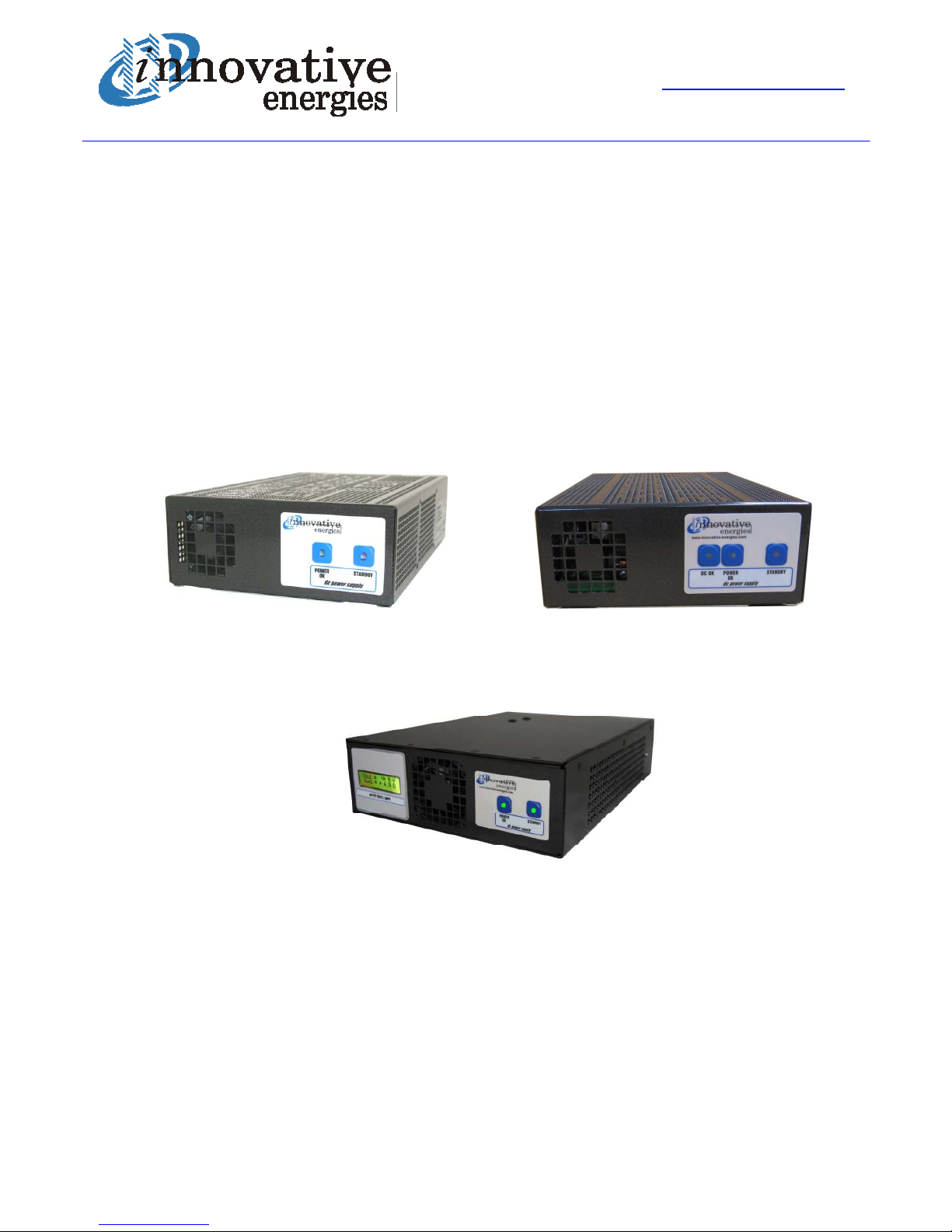
AC/DC POWER SUPPLY & FLOAT CHARGER
(for lead acid batteries)
SR250A/SR500A/SR750A
User Manual
www.innovative.co.nz
Phone: +64 9 835 0700
Fax: +64 9 837 3446
NZ Freephone: 0800 654 668
AU Freephone: 1800 148 494
Email: [email protected]
Page 2
Specifications are subject to change without notice. No liability accepted for errors or omissions.
2
1. INTRODUCTION
The SR250A-750A range is designed for use as a very accurate AC to DC power supply, or float charger for
lead acid batteries. Note that for float charging the output voltage must be set to approximately 15% above
the nominal battery voltage. This is done as the default voltage for the 12V model but must be specified at
time of order for all higher voltage models.
2. CONNECTIONS
If used as a float charger always connect the positive output of the power supply to the positive terminal of
the battery. The charger may be permanently connected to float charge lead acid batteries but it is essential
to periodically check the electrolyte level of flooded cells as there is always some evaporation.
Where screw/plug in terminals are fitted (eg. SR500A24FXL), and there are two terminals provided for each
polarity, both terminals must be used. This is to ensure that the current rating of the terminal block is not
exceeded.
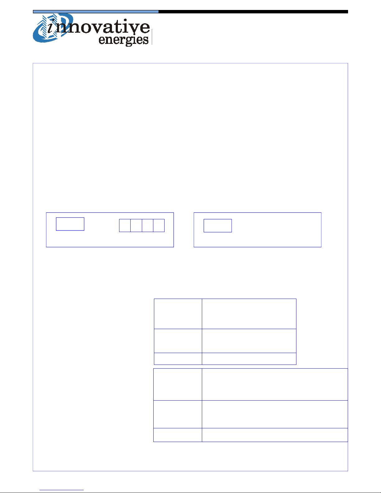
LED INDICATION
DC OK*2 POWER OK*3 STANDBY
NORMAL ON ON OFF
STANDBY As above OFF ON
MODE
DC LOW*4 OFF ON OFF
MODE
LED INDICATION
POWER OK*1 STANDBY
DC PRESENT ON OFF
STANDBY As above ON
DC ABSENT OFF OFF
3. LED INDICATION CODES
3.1 -A Standard version
3.2 -D Alarm version
CONNECTION LAYOUT
Screw Conn. Output Stud Conn. Output
AC INPUT
AC INPUT
+ + - -
DC OUTPUT DC OUTPUT
(+) (-)
*1 POWER OK LED indicates
DC present on output terminals
(either from PSU or battery, if
connected)
*2 DC OK
LED indicates DC output is present, either from PSU or battery (if connected)
*3 POWER OK LED indicates input power on (unless there is a short circuit on the output)
*4 DC LOW settings as in para. 3.3
Page 3
Specifications are subject to change without notice. No liability accepted for errors or omissions.
3
3.3. -L Alarm version (with DC high alarm)
DC OK LED: Slow flash: DC LOW Settings: PSU: 0.83 xVnom. Charger: 1.83V/cell
Fast flash: DC HIGH Settings: PSU: 1.2 x Vnom Charger: 2.5V/cell
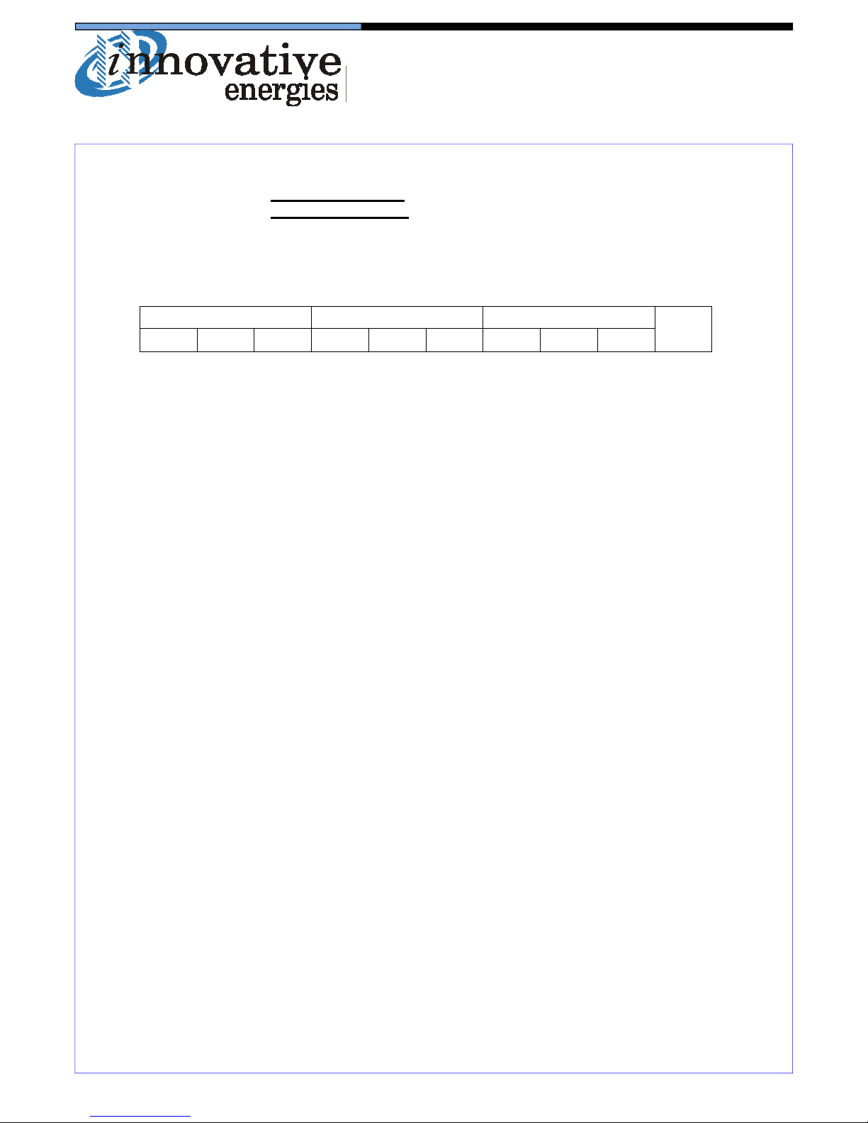
4. ALARM TERMINAL LAYOUT (for -D & -L*5 versions):
5. INPUT CONNECTIONS FOR DC INPUT MODELS
BROWN : POSITIVE +
BLUE: NEGATIVE GREEN/YELLOW: EARTH
6. FG (Frame Ground)
Where provided, this terminal provides a connection to the metal case for an earthing point.
7. STANDBY FUNCTION
Pushing the STANDBY button turns the output of the power supply off. If there is a battery con
nected, the DC OK LED remains on even though the power supply is turned off (except for -P versions with output diode)
Relay contacts shown in de-energised state (ie when there is a fault condition).
Alarm relays are energised when power supply is operating normally.
*5 No DC HIGH alarm relay fitted on HV versions, eg. SR500L92, SR750L92
DC HIGH *5 MAINS FAIL DC OK
COM NC NO COM NC NO COM NC NO
FG
Page 4
Specifications are subject to change without notice. No liability accepted for errors or omissions.
4
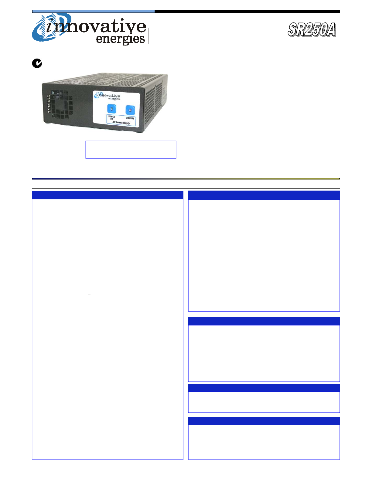
Industrial quality AC/DC power supply
Standalone - bench top or fixed mounting
Front panel controls & indication
Suitable for float charging of lead acid batteries
Optional serial communications port, SR250L
Optional relay alarm outputs - model SR250D,P
Conservative design for long life
Optional DC input
Precise voltage and current control
Efficient switch mode design
Suitable for parallel operation
Optional temperature compensation for charging
ISO9001 design management system
PHYSICAL
AC Input connector
DC Connections
Enclosure
Dimensions
Weight
Indication LEDs
Alarm relay output
(option)
Standby Mode
ENVIRONMENTAL
Operating
temperature
Storage temperature
Humidity
Cooling
♦ 24 Month Warranty
STANDARDS
EMI
Safety
IEC320 socket
M6 brass stud or plug-in socket with screw
terminals
Zinc plated steel /powder coated lid
150W x 61H x 242D (excl. terminals)
1.7 Kg
Standard: Power OK, Standby
With alarms: DC OK, Power OK, Standby
C - NO - NC changeover rated 1A /50V DC,
32VAC
Turns off DC output of PSU
Input ▪ standard
▪ option
Fusing
Overcurrent Protection
OVP
Thermal Protection
Isolation
Efficiency
Inrush current
Output Power
Output Voltages
Voltage adj. range
Line Regulation
Load Regulation
Noise
Drift
Hold-up time
ELECTRICAL
180-264 or 88-132V, 45-65Hz (internal link
select)
110VDC (99 -150) or 220VDC(180-270)
(specify at time of order if DC input required)
Internal input fuse
Constant current limit under overload and
short circuit conditions
Over-voltage protection on output
at ~ 130% of nominal output voltage
Yes, self resetting
1KV DC input - output / earth
> 85%
Soft start circuit
250W
Refer to model table
85 - 115% of Vout
<0.2% over AC input range
<0.4% open circuit to 100% load
<1%
0.03% / °C
15 - 20 ms without battery
0 - 50 °C ambient at full load
De-rate linearly >50 °C to no load @ 70 °C
-10 to 85 °C ambient
0 - 95% relative humidity non-condensing
24V & above: natural convection
12V: fan cooled
To CISPR 22 / EN55022 class A
To IEC950 / EN60950 / AS/NZS3260
ACCESSORIES SUPPLIED
Mounting feet together with screws
AC power cord 1.5m with IEC320 socket and NZ/Aust plug
Mating screw-terminal plug for alarm outputs
Crimp lugs for stud terminal versions
DC screw terminal plug-in connector for ‘X’ version
Ideal as a Standby Float Charger
for lead acid batteries
incl. SR250D, SR250L, SR250P
Global Solutions Personal Focus
SPECIFICATIONS
All specifications are typical at nominal input, full load and at 20°C unless otherwise stated.
Page 5
Specifications are subject to change without notice. No liability accepted for errors or omissions.
5
OPTIONS
Temperature
Compensation for
charging
Alarms (SR250D..)
Extra DC Fault Alarm
(SR250L..)
Alarm Relay Contacts
Internal output diode
(SR250P..)
Earth Fault Alarm
(external)
If external surge suppressor fitted
Temperature sensor on 1.7m lead with
adhesive pad: -4mV / °C / cell ±10%
Order Code: +TEMPCO
Mains/PSU fail (or PSU in standby mode)
DC low (Battery low or PSU low) - set at
92% of nominal voltage.
Special version available: Battery low
alarm operates when mains power is on,
order code: SFMCT-OA v1.1
Alarm level to be specified at time of order,
eg. DC high
C - NO - NC full changeover rated 1A /50V
DC, 32VAC
Incl. alarms & output diode for N+1 redundancy, internal diode not available for 12V
models.
Detects leakage to earth of DC output and
provides relay output
Order Code: +ALARM/EFDM (20-60V)
Replace end suffix –L with –M (230VAC input
version) internal MOV is rated at higher voltage than external surge suppressor
MODELS
Power Supply Battery Charger
Adjustable
range (V)
Output
Volts
(factory default)
Output
Current (A)
(continuous)
Output
Volts*
(Charging)
Output
Current (A)
(Charging)
SR250A12
13.8 18.1 @13.8V 13.8 18.1 11-14
SR250A24
24 10.4 27.6 9.0 22-28
SR250A30
30 8.3 34.5 7.2 28-36
SR250A36
36 6.9 41.4 6.0 34-43
SR250A48
48 5.2 55.2 4.5 45-57
SR250A7.5
7.5 20 6.9 20 6.8-8
SR250A60
60 4.1 69.0 3.6 54-66
STANDARD MODEL TABLE
* Please specify on ordering if the
unit is to be used for float charging
(except for 12V model which is set
at 13.8V by default).
MODEL IDENTIFICATION CODES
SR250A12 T F S L-485
L = 230V AC + switch Blank = 230V AC no switch
U = 110V AC + switch G = 110V AC no switch
H = 110V DC + switch J = 110V DC no switch
M = 230V AC + switch +
300V MOV
(to be used with IEOVPHVAC)
K = motorhome version (please refer to separate data sheet)
Input voltage and front
panel standby switch
S = Stud X = Plug in /screw terminal block
F = Fan Blank = No fan
T = Yes Blank = No
12, 24, 30, 36, 48, 60
Output DC Connector type:
Fan cooled:
Temperature Compensation
DC output: Nominal voltage
A = Standard PSU
D = Standard with alarms
L = D version with extra DC fault alarm and optional comms port
P = D with output diode for parallel redundancy (>24V only)
Function
Optional communication
port for SR250L versions
Power
250W
250 Watt
AC/DC Stand Alone Power Supply/Float Charger
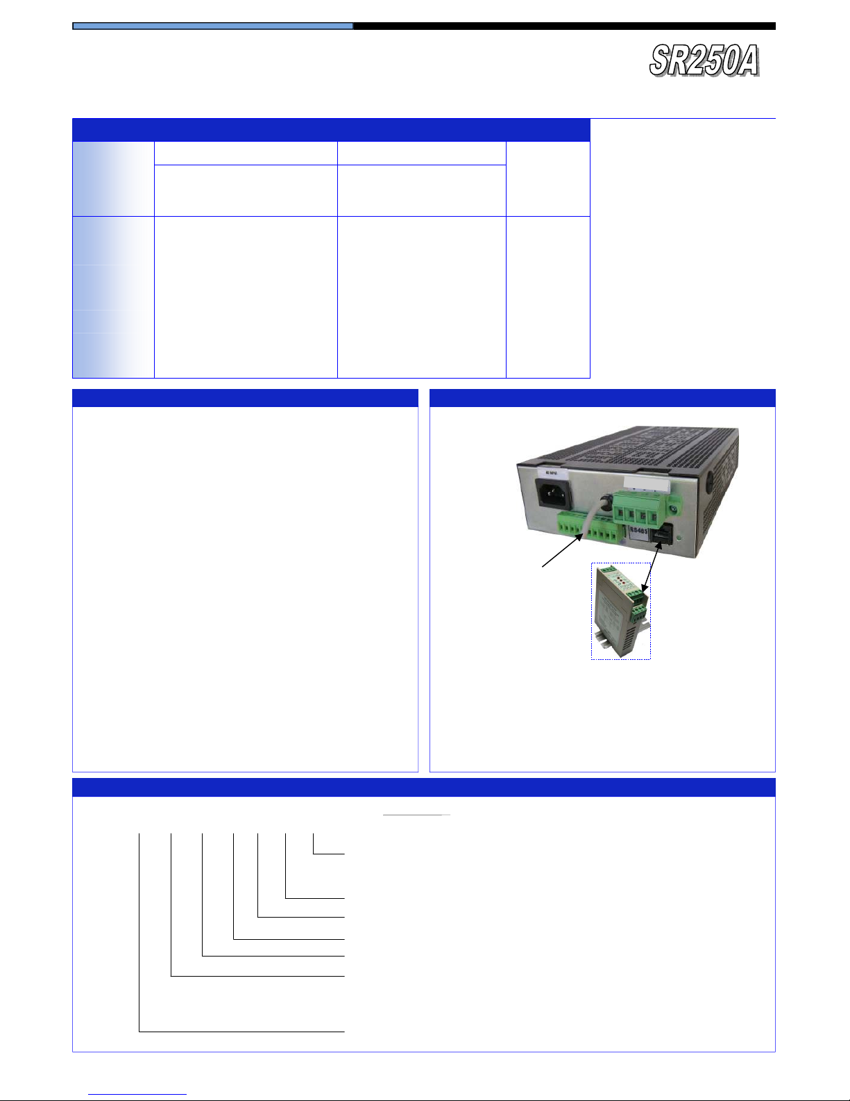
OPTIONAL COMMUNICATION PORT - SR250L….
• Includes three relay alarm outputs
• Serial (RS232 or RS485) or ethernet port
• SNMP protocol or ASCII code
• Optional MODBUS protocol converter for use with RS485
• Example of code: SR250L12FSL-LAN+ (for SNMP
model)
O
U
T
P
U
T
Optional Protocol
Converter
+PROTOCONMB
Optional temperature
compensation probe
incl. SR250D, SR250L, SR250P
485 = RS485 232 = RS232
LAN + = Ethernet (SNMP) LAN = Ethernet (ASCII)
Page 6
Specifications are subject to change without notice. No liability accepted for errors or omissions.
6
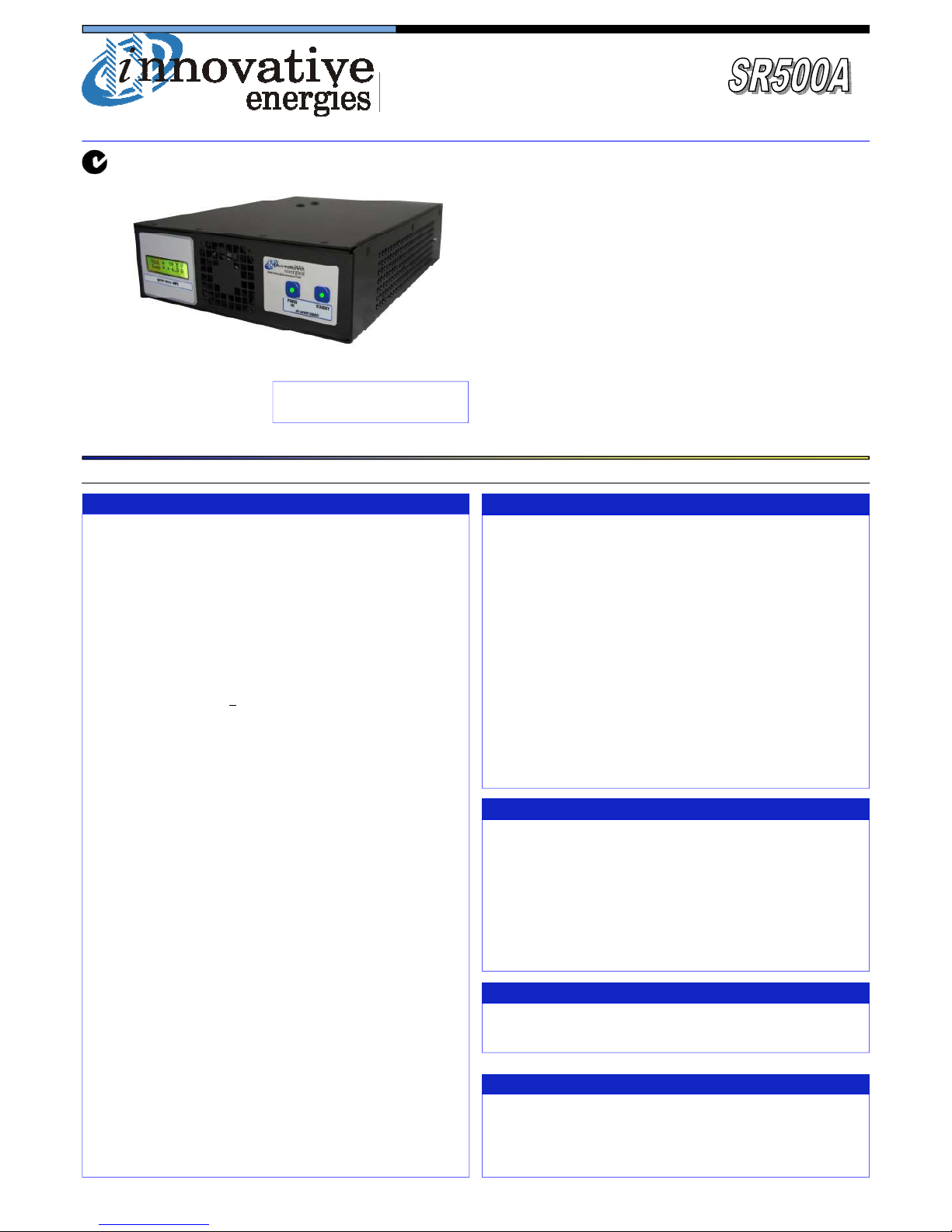
Industrial quality AC/DC power supply
Standalone - bench top or fixed mounting
Front panel controls & indication
Suitable for float charging of lead acid batteries
Suitable for parallel operation
Conservative design for long life
Precise voltage and current control
Optional temperature compensation for charging
Optional relay alarm outputs
Optional DC input
Optional communications port: RS232, RS485 or
ethernet
Optional protocols available: Modbus, SNMP or
ASCII code
♦ 24 Month Warranty
STANDARDS
EMI
Safety
Input ▪ standard
▪ option
Fusing
Overload protection
Isolation
Over voltage protection
Efficiency
Inrush current
Output power
Output voltage
Line regulation
Load regulation
Noise
Drift
Hold-up time
Thermal protection
Parallel operation
- higher power
- N+1 redundancy
ELECTRICAL
180V - 264V, 45-65Hz
88V - 132VAC 45-65Hz
Internal input fuse
Constant current limit under overload and
short circuit conditions (except DC input versions which have primary current limit)
1KV DC input - output / earth
130% of nominal output voltage
> 85%
Soft start circuit
500W
Refer to model table
<0.2% over AC input range
<0.4% open circuit to 100% load
<1%
0.03% / °C
15 - 20 ms without battery
Yes, self resetting
Yes
Addition of external output diodes optional
Use SR500D… with external output diodes
ENVIRONMENTAL
Operating
temperature
Storage temperature
Humidity
Cooling
0 to + 50 °C ambient at full load
De-rate linearly >50 °C to no load @ 70 °C
-10 to 85 °C ambient
0 - 95% relative humidity non-condensing
Fan cooled
To CISPR 22 / EN55022 class A
To IEC950 / EN60950 / AS/NZS3260
ACCESSORIES SUPPLIED
Mounting feet together with screws
AC power cord 1.5m with IEC320 socket and NZ/Aust plug
Mating screw-terminal plug for alarm outputs
Crimp lugs for stud terminal versions
DC screw terminal plug-in connector for ‘X’ version
Ideal as a Standby Float Charger
for lead acid batteries
PHYSICAL
AC input connector
DC connections
Alarm connections
Enclosure
Dimensions
Weight
Indication LEDs
Standby switch
IEC320 inlet socket
M8 brass stud or plug in/screw terminal block
Plug-in screw terminal block
Powder coated steel
225W x 70H x 304D mm (excl. terminals)
4.3 Kg
Standard: Power OK, Standby
With alarms: DC OK, Power OK, Standby
Turns off DC output of PSU
incl. SR500D, SR500L
Optional internal V/I
meter shown
Global Solutions Personal Focus
SPECIFICATIONS
All specifications are typical at nominal input, full load and at 20°C unless otherwise stated.
Page 7
Specifications are subject to change without notice. No liability accepted for errors or omissions.
7
STANDARD MODEL TABLE
OPTIONS
Temperature
compensation for
charging
Alarms - SR500D..
- SR500L..
Alarm contacts
DC Input
Earth fault alarm
(external to PSU))
Temperature sensor on 1.7m lead with
adhesive pad: -4mV / °C / cell ±10%
Order Code: +TEMPCO
Mains fail (or PSU in standby mode)
DC low (Battery low or PSU low)
- Charger: set at 1.83V/cell
- PSU: set at 83% V out
•
As SR500D.. + DC high alarm (NB: no
alarm relay fitted on HV versions, only
LED indication)
C - NO - NC changeover rated 1A /50V DC,
32VAC
110VDC (99-150) or 220VDC (180-270)
Please note that an external fuse or MCB
must be fitted on the output for short circuit
protection.
Detects leakage to earth of DC output and
provides relay output
Code: +ALARM/EFDM (20-60V)
+ALARM/EFDH (61-150V)
* Please specify on ordering that
unit is to be used for float charging
(except for 12V model which is set
at 13.8V by default).
OPTIONS
Communications Port
Internal V/I meter
Mounting options:
19”rack mount
Wall mount enclosure
Choice of RS485, RS232, ethernet (SNMP or
ASCII)
Available on SR500L… models
Add code: +INT-METER
2U sub rack available, Code: SR-RM2U
Optional V/I meter, Code: SR-METER
PSU may be fitted into enclosure with MCBs
and terminals. Code: SEC-SR
500 Watt
AC/DC Stand Alone Power Supply/Float Charger
incl. SR500D, SR500L
MODELS
Power Supply Battery Charger
Output
Volts
(factory default)
Output
Current (A)
Output
Volts*
(Charging)
Output
Current (A)
(Charging)
SR500A12
13.8
36.2
(41.6 @ 12V)
13.8 36.2 11-14
SR500A24
24 20.8 27.6 18.2 22- 29
SR500A30
30 16.6 34.5 14.5 28-36
SR500A36
36 13.8 41.4 12.0 34-43
SR500A48
48 10.4 55.2 9.1 45-57
SR500A91
96 5.2 110 4.5 90-115
SR500A92
108 4.6 124 4.0 100-130
SR500A93
120 4.1 138 3.6 110-145
Adjustable
range (V)
MODEL IDENTIFICATION CODES
SR500A 12 T F S L-LAN
LAN = ethernet (ASCII) LAN+ = ethernet (SNMP) 232 = RS232
485 = RS485 No = bl ank
Input voltage and front panel
standby switch:
Output DC Connector type:
Cooling
Temperature Compensation
DC output: Nominal voltage
A = Standard PSU/Float Charger
D = A version with alarms
L = D version with DC high alarm and optional comms port
Function
Power
500W
Optional communication port
for SR500L versions
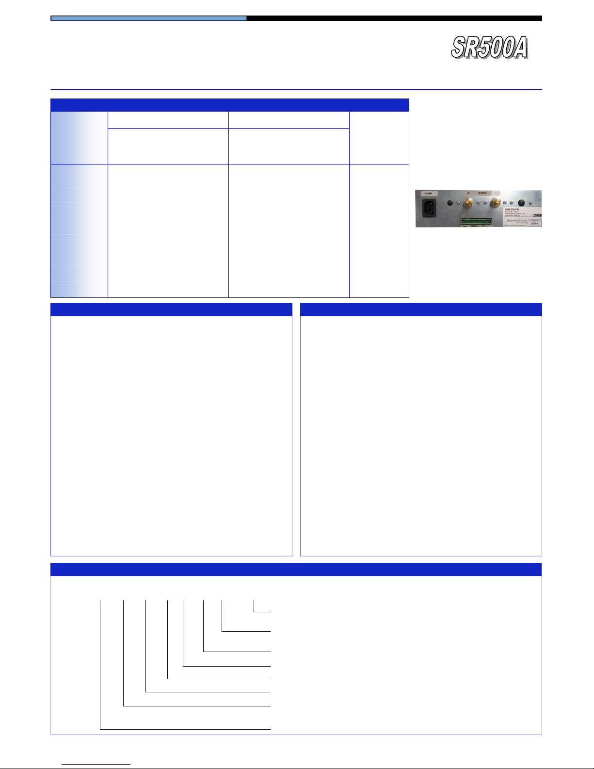
Rear view of SR500D….or SR500L...
with alarm contacts and no communication port option
L = 230V AC + switch Blank = 230V AC no switch
U = 110V AC + switch G = 110V AC no switch
H = 110V DC + switch J = 110V DC no switch
S = Stud X = Plug in /screw terminal block
F = Fan
T = Yes Blank = No
12, 24, 36, 48, 91 = 96V, 92 = 108V, 93 = 120V
Page 8
Specifications are subject to change without notice. No liability accepted for errors or omissions.
8
incl. SR750D, SR750L
Global Solutions Personal Focus
Industrial quality AC/DC power supply
Standalone - bench top or fixed mounting
Front panel controls & indication
Suitable for float charging of lead acid batteries
Suitable for parallel operation
Conservative design for long life
Precise voltage and current control
Optional temperature compensation for charging
Optional relay alarm outputs
Optional DC input
Optional communications port: RS232, RS485 or
ethernet
Optional protocols available: Modbus, SNMP or
ASCII code
♦ 24 Month Warranty
STANDARDS
EMI
Safety
Input ▪ standard
▪ option
Fusing
Overload protection
Isolation
Over voltage protection
Efficiency
Inrush current
Output power
Output voltage
Line regulation
Load regulation
Noise
Drift
Hold-up time
Thermal protection
Parallel operation
- higher power
- N+1 redundancy
ELECTRICAL
230VAC (180 - 264), 45-65Hz
110VAC (88 -132), 45-65Hz
Internal input fuse
Constant current limit under overload and
short circuit conditions (except DC input versions which have primary current limit)
1KV DC input - output / earth
130% of nominal output voltage
> 85%
Soft start circuit
750W
Refer to model table
<0.2% over AC input range
<0.4% open circuit to 100% load
<1%
0.03% / °C
15 - 20 ms without battery
Yes, self resetting
Yes
Addition of external output diodes optional
Use SR750D… with external output diodes
ENVIRONMENTAL
Operating
temperature
Storage temperature
Humidity
Cooling
0 to + 50 °C ambient at full load
De-rate linearly >50 °C to no load @ 70 °C
-10 to 85 °C ambient
0 - 95% relative humidity non-condensing
Fan cooled
To CISPR 22 / EN55022 class A
To IEC950 / EN60950 / AS/NZS3260
ACCESSORIES SUPPLIED
Mounting feet together with screws
AC power cord 1.5m with IEC320 socket and NZ/Aust plug
Mating screw-terminal plug for alarm outputs
Crimp lugs for stud terminal versions
DC screw terminal plug-in connector for ‘X’ version
Ideal as a Standby Float Charger
for lead acid batteries
PHYSICAL
AC input connector
DC connections
Alarm connections
Enclosure
Dimensions
Weight
Indication LEDs
Standby switch
IEC320 inlet socket
M8 brass stud or plug in/screw terminal block
Plug-in screw terminal block
Powder coated steel
225W x 70H x 304D mm (excl. terminals)
4.3 Kg
Standard: Power OK, Standby
With alarms: DC OK, Power OK, Standby
Turns off DC output of PSU
Optional internal V/I
meter shown
SPECIFICATIONS
All specifications are typical at nominal input, full load and at 20°C unless otherwise stated.
Page 9
Specifications are subject to change without notice. No liability accepted for errors or omissions.
9
MODELS
Power Supply Battery Charger
Output
Volts
(factory default)
Output
Current (A)
(continuous)
Output
Volts*
(Charging)
Output
Current (A)
(Charging)
SR750A12
13.8
54
(54 @ 11-14V)
13.8 54 11-14
SR750A24
24 31.2 27.6 27 22- 29
SR750A30
30 25 34.5 21.7 28-36
SR750A36
36 20.8 41.4 18 34-43
SR750A48
48 15.6 55.2 13.6 45-57
SR750A91
96 7.8 110 6.8 90-115
SR750A92
108 6.9 124 6.0 100-130
SR750A93
120 6.2 138 5.4 110-145
Adjustable
range (V)
750 Watt
AC/DC Stand Alone Power Supply/Float Charger
incl. SR750D, SR750L
STANDARD MODEL TABLE
* Please specify on ordering that
unit is to be used for float charging
(except for 12V model which is set
at 13.8V by default).
Rear view of SR750D…or SR750L...
with alarm contacts and no communication port option
OPTIONS
Temperature
compensation for
charging
Alarms - SR750D..
- SR750L..
Alarm contacts
DC Input
Earth fault alarm
(external to PSU))
Temperature sensor on 1.7m lead with
adhesive pad: -4mV / °C / cell ±10%
Order Code: +TEMPCO
Mains fail (or PSU in standby mode)
DC low (Battery low or PSU low)
- Charger: set at 1.83V/cell
- PSU: set at 83% V out
•
As SR750D.. + DC high alarm (NB: no
alarm relay fitted on HV versions, only
LED indication)
C - NO - NC changeover rated 1A /50V DC,
32VAC
110VDC (99-150) or 220VDC (180-270)
Please note that an external fuse or MCB
must be fitted on the output for short circuit
protection.
Detects leakage to earth of DC output and
provides relay output
Code: +ALARM/EFDM (20-60V)
+ALARM/EFDH (61-150V)
OPTIONS (continued)
Communications port
Internal V/I meter
Mounting options:
19”rack mount
Wall mount enclosure
Choice of RS485, RS232, ethernet (SNMP or
ASCII)
Available on SR750L… models
Add code: +INT-METER
2U sub rack available, Code: SR-RM2U
Optional V/I meter, Code: SR-METER
PSU may be fitted into enclosure with MCBs
and terminals. Code: SEC-SR
MODEL IDENTIFICATION CODES
SR750A 12 T F S L-LAN
LAN = ethernet (ASCII) LAN+ = ethernet (SNMP) 232 = RS232
485 = RS485 No = bl ank
L = 230V AC + switch Blank = 230V AC no switch
U = 110V AC + switch G = 110V AC no switch
H = 110V DC + switch J = 110V DC no switch
Input voltage and front
panel standby switch:
S = Stud X = Plug in /screw terminal block
Output DC Connector type:
F = Fan
Cooling
T = Yes Blank = No
Temperature Compensation
12, 24, 36, 48, 91 = 96V, 92 = 108V, 93 = 120V
DC output: Nominal voltage
A = Standard PSU/Float Charger
D = A version with alarms
L = D version with DC high alarm and optional comms port
Function
Power
750W
Optional communication port
for SR750L versions
Page 10
Specifications are subject to change without notice. No liability accepted for errors or omissions.
10
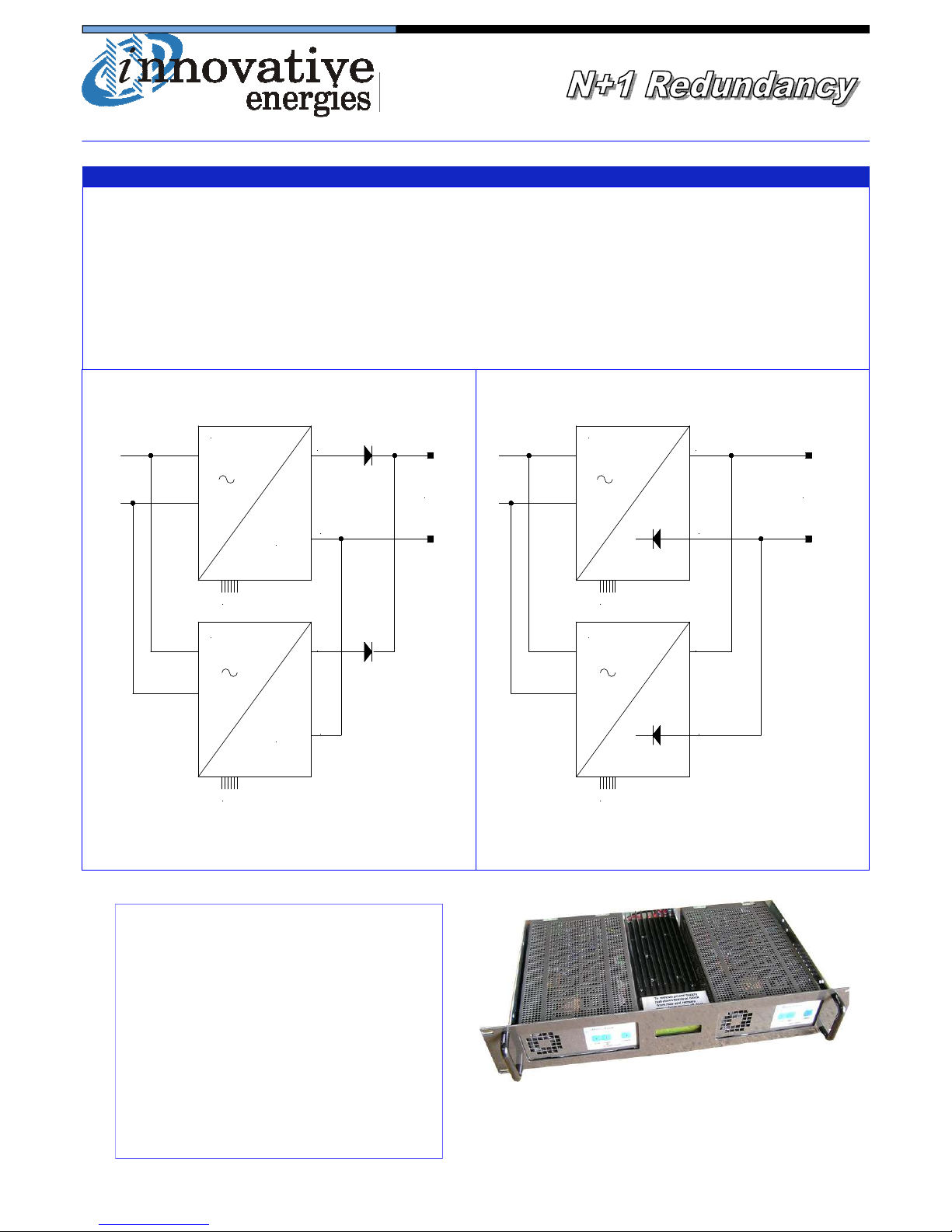
Two or more SRxxxA, SRxxxD or SRxxxL power supplies may be connected in parallel for increased power or parallel
redundancy. Figure 1 below shows two SR xxx D units connected with external diodes. It is essential that the wiring
from each unit to the load is kept identical for equal power sharing particularly when diodes are not used.
Diodes can be fitted inside some power supplies (see models listed below). The SRxxxP series identifies when an internal diode is fitted in the power supply. Figure 2 shows two SRxxxP units connected in parallel.
CONNECTION FOR PARALLEL REDUNDANCY
INTERNAL diodes (in negative leg) can be fitted
to the following models only:
100W: SR100P24, SR100P36,
SR100P48
250W: SR250P24, SR250P30,
SR250P36, SR250P48, SR250P60
All other models have diodes external to the
power supply, eg fitted into a 2U rack as shown
in the photo to the right.
2U rack with 2 x SR250D12 power
supplies and decoupling diodes on
heatsink plus V/I meter
SRxxx D
SRxxx D
ALARMS
ALARMS
+
-
+
-
LOAD
=
=
SRxxx P
SRxxx P
ALARMS
ALARMS
+
-
+
-
LOAD
Fig. 1: Two SRxxx D with external diodes Fig. 2: Two SRxxx P connected in parallel
Page 11

Specifications are subject to change without notice. No liability accepted for errors or omissions.
11
Safety
The user is responsible for ensuring that input and output wiring segregation complies with local standards and that in
the use of the equipment, access is confined to operators and service personnel. A low resistance earth connection is
essential to ensure safety and additionally, satisfactory EMI suppression (see below).
HAZARDOUS VOLTAGES EXIST WITHIN A POWER SUPPLY ENCLOSURE AND ANY REPAIRS MUST
BE CARRIED OUT BY A QUALIFIED SERVICEPERSON.
Electrical Strength Tests
Components within the power supply responsible for providing the safety barrier between input and output are constructed to provide electrical isolation as required by the relevant standard. However EMI filtering components could be
damaged as result of excessively long high voltage tests between input, output and ground. Please contact our technicians for advice regarding electric strength tests.
Earth Leakage
The EMI suppression circuits causes earth leakage currents which may be to the maximum allowable of 3.5mA.
Ventilation
High operating temperature is a major cause of power supply failures, for example it has been well documented that a
10oC rise in the operating temperature of a component will halve its expected life. Therefore always ensure that there is
adequate ventilation for the equipment. Batteries and cooling fans also suffer shortened lifetimes if subjected to high
ambient temperatures - both should be included in a routine maintenance schedule to check for signs of reduced efficiency.
Water / Dust
Every effort must be made in the installation to minimise the risk of ingress of water or dust. Water will almost always
cause instant failure. The effects of dust are slower in causing failure of electronic equipment but all electrical equipment should be cleaned free of any dust accumulation at regular intervals. This is particularly important where internal
fans are fitted.
Electromagnetic Interference (EMI)
Switching power supplies and converters inherently generate electrical noise. All wiring should be as short as practicable and segregated from all equipment wiring which is sensitive to EMI. Residual noise can be reduced by looping DC
wiring through ferrite cable sleeves. These are most effective as close to the power supply as possible and as many
turns of the wire taken through the core (+ and - in the same direction) as the core will accommodate.
Fuse ratings
Check that the wiring and fuses or MCBs match the rating of the PSU or converter. Adequate fuse protection of battery
circuits is very important owing to the large potential currents available from batteries.
Connection polarity
It is critical to check the polarity carefully when connecting DC power supplies and chargers to equipment. Boost
chargers and some float chargers usuall have reverse polarity protection (RPP), which can be electronic (nondestructive) or by an internal fuse which needs to be replaced if a battery is connected in reverse.
PSU = power supply unit BCT = battery condition test ECB = electronic circuit breaker
ELVD = electronic low voltage disconnect RPP = reverse polarity protection EMI = electromagnetic interference
Glossary of terms used in our user manuals
SNMP = Simple Network Management
Protocol
LAN = local area network DOD = depth of discharge
Page 12
Specifications are subject to change without notice. No liability accepted for errors or omissions.
12
Innovative Energies Limited
Phone: +64 9 835 0700
Fax: +64 9 837 3446
Email: [email protected]
Online: www.innovative.co.nz
In Person: 1 Heremai Street, Henderson, Auckland, NZ
Post: PO Box 19501, Auckland 1746, NZ
TERMS OF WARRANTY
Innovative Energies Ltd warrants its power supplies for 24 months (two years) from date of shipment against material
and workmanship defects.
Innovative Energies' liability under this warranty is limited to the replacement or repair of the defective product as long
as the product has not been damaged through misapplication, negligence, or unauthorized modification or repair.
21/12/11
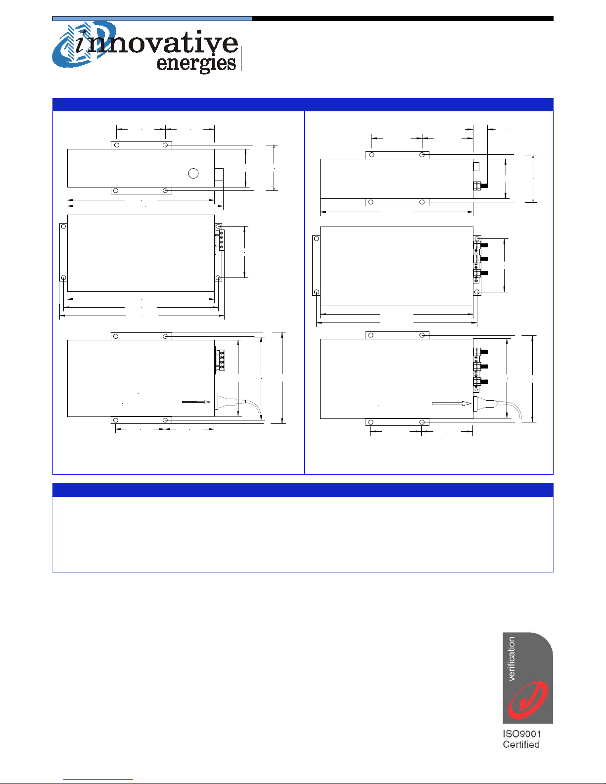
DIMENSIONS FOR SR250
76.5 mm
60 mm
80mm
242mm
80mm
80mm
242mm
253mm
80mm
162mm
150mm
270mm
278mm
NOTE
power cord protrudes
172mm
80mm
The Standard ac
approx. 70mm
76 .5mm60 mm
80mm
242mm
80mm
20mm
80mm
242mm
253mm
80mm
162mm
150mm
80mm
NOTE
power cord protrudes
The Standard ac
approx. 70mm
Fig. 1: Plug in/ screw terminal connectors Fig. 2: Stud connectors
Global Solutions Personal Focus
 Loading...