

Page 1
User Guide
Ap
InnovaSON
ZC du Kenyah
56400 Plougoumelen
France
Sensoft 8.1 full
Sensoft 9 installation
(Sensoft 9 Addendum updates
sections 3 and 4 of this user guide)
ril 2005
Page 2

Page 3

Headquarters
Zone du Kenyah
F-56400 Plougoumelen
FRANCE
tel : +33 (0) 297 24.34.34
fax : +33 (0) 297 24.34.30
www.innovason.com
Page 4

TABLE OF CONTENTS 1
Attention: veuillez consulter le chapitre 10 avant toute manutention ou utilisation de la console.
Warning: please read carefully section 10 before handling or using the console.
Achtung: bitte lesen sie zuerst Kapitell 10 for jedem Verladen oder Verwendung des Pultes.
Table of Contents
Section Page
1 Digital mixing in Live sound
1.A
1.B
1.C
1.D
Sensoft 8.1 :a brief history
Fader assignment
The assignable functions
Spread zones
2 THE Sy48 CONSOLE
2.A
2.B
2.B.1 L.E.M : Optional External Mix Box 2.3
2.C
2.C.1 Dimensions and general information 2.6
2.C.2 The Quadfad module 2.8
2.C.3 The CHANNEL CONTROL panel 2.8
2.C.4 Screen and UTILITIES panel 2.8
2.C.5 On the front of the console 2.9
2.C.6 On the back of the console 2.9
2.C.7 Control layout 2.10
2.D
Sy48 : Overview of the product
Personalization, options
Description of the Sy48
Precautionary measures, safety and
1.1
1.1
1.2
1.3
1.4
2.1
2.1
2.3
2.6
2.12
warnings
2.E
2.F
2.G
2.G.1 Audio connections 2.13
2.G.2 Internal Screen, external Screen 2.14
2.G.3 Connecting MIDI equipment 2.14
2.G.4 Connection of an external power supply 2.14
2.G.5 Connecting an external PC 2.14
2.G.6 Connecting an optional Stage-Box
2.G.7 Digital audio clock sync with external
2.G.8 Connecting headphones
2.H
2.H.1 Power up sequence 2.19
2.H.2 First checks 2.21
Manipulation and transport
Power supplies and EC standards
Connections
devices
Powering up
3 Sensoft 8.1
Your first mix : a simple step-by step
3.A
2.13
2.13
2.13
2.15
2.17
2.18
2.19
3.1
3.1
example
3.A.1 Console configuration 3.2
3.A.2 Patching.. 3.4
3.A.3 Some routing 3.6
3.A.4 Creating and using a subgroup 3.8
3.A.5 Spreading inouts 3.11
3.A.6 Creating and using a VCA 3.13
3.A.7 Spreading a Master 3.14
3.A.8 Spreading an Aux 3.17
3.A.9 Creating a matrix 3.18
4 Digital mixing in Live Sound
4.A
4.A.1 Control surface layout
4.A.2 Fader configuration : The Hardware
4.B
4.B.1 General characteristics 4.3
4.B.2 Layout of physical inputs 4.3
4.B.3 Universal analog inputs 4.4
4.B.4 Analog line inputs 4.4
4.B.5 Distant inputs (Stage Box) 4.5
4.C
4.C.1 X
4.C.2 Preamp to fader assignment grid (P
4.C.3 Pre-amp settings (Gain, 48V) 4.15
4.C.4 Delay 4.16
4.C.5 Phase inversion and the high-pass filter 4.17
4.C.6 Dynamics 4.18
4.C.7 Equalizer 4.21
4.C.8 Inserting an external device 4.22
4. C . 9 MUTE and CUE functions 4.25
4.D Mix busses
4.D.1 DSP resources: some important points 4.27
4.D.2 Spreading the outputs 4.28
4.D.3 Assignment of mix busses to physical
4.D.4 Basic principles of routing 4.37
4.D.5 Definition ‘pre/post fader’ and Pan
4.D.6 A special bus : the Matrix 4.47
4.D.7 The Monitor bus 4.49
4.D.8 Master busses 4.58
4.D.9 Bus processing and inserts 4.58
4.D.10 Hyperdrive outputs’ processing control 4.59
4.D.11 Principles of fader functions, Fader Mode 4.60
4.D.12 MUTE and CUE functions 4.62
4.E
Basic principle of the control surface
Configuration window
Audio inputs
Input signal path
FAD : the principles 4.6
IN)
outputs (Patch OUT)
settings on busses
The MUXIPAIRE bus, the Direct I/O
ATCH
4.1
4.1
4.1
4.2
4.3
4.6
4.10
4.27
4.32
4.41
4.63
grid
4.E.1 The Direct I/O grid 4.64
4.F
4.F.1
4.F.2 VCA Assignment 4.66
4.G
The VCA function
VCA function logic 4.65
Talk-Back
4.65
4.66
User Guide - © InnovaSON – February 2005
Page 5

2 TABLE OF CONTENTS
Section Page
5 Structure of a performance
General description
5.A
5.B
5.B.1 File edition 5.1
5.B.2 Changing a file 5.4
5.B.3 Saving a file 5.4
5.B.4 Exporting, Importing, deleting a file 5.5
5.C
5.C.1 Saving a page 5.6
5.C.2 LOAD and GOTO a page 5.6
5.C.3 Inserting a page 5.7
5.D
5.E
5.E.1 Generalities 5.9
5.E.2 MIDI Program Change OUT 5.9
5.E.3 MIDI Program Change IN 5.11
5.E.4 MIDI Time Code Automation 5.12
5.E.5 Cross-Fade 5.14
5.E.6 The Cross-Time Fader 5.16
Files and pages management
Pages management
Navigating in a file
Automation (sequencing , calling up pages)
6 Advanced Functions
Generator and oscillator
6.A
6.B
6.C
6.D
6.E
FLAT function for resetting parameters
Copy and Paste
OverRam - Updating pages in RAM
Relax Mode - disconnecting parameters
5.1
5.1
5.1
5.6
5.8
5.9
6.1
6.1
6.1
6.2
6.3
6.5
from the automation
6.F
6.F.1 What are I/O parameters ? 6.6
6.F.2 The link I/O grid 6.6
6.G
Link I/O - Input/ Output parameter links
Link Channel – channel parameter
6.6
6.7
links
6.G.1 What are the channel parameters ? 6.7
6.G.2 The channel link grid 6.8
6.H
6.I
Temporary cancellation of a link
MUXI window – display and modification
6.9
6.10
of outputs
6.J
Off Line – disconnecting the console
6.11
from the audio racks
6.K
6.K.1 The BANK Menu and general operation 6.12
6.K.2 Save and load shortcuts 6.13
6.L
6.M
Processing libraries
Request Mode (RQST)
The ADJ function – automatic
6.12
6.13
6.15
adjustment of preamps
6.N
Sending MIDI messages using the MUTE
6.16
buttons
6.O
6.P
Sending Fader Start MIDI messages
LOCK – Password Protection for the
6.17
6.18
console
6.Q
The General Preferences window
7 Sensoft Offline
General operation of the mouse and
7.A
6.20
7.1
7.1
keyboard
7.B
Detailed operation and access to the
7.2
various windows
7.B.1 The HARDWARE CONFIGURATION
window
7.2
7.B.2 The PATCH IN grid window 7.3
7.B.3 The PATCH OUT grid window 7.5
7.B.4 The DIRECT I/O and Insert Grid window 7.6
7.B.5 The LINK CHANNEL window 7.7
7.B.6 The LINK I/O window 7.8
7.B.7 The RELAX, FADER-START and MUTE
7.B.8 The PAN window 7.10
7.B.9 The PASTE and OVERRAM windows 7.11
7.B.10 The MUXI window 7.13
7.B.11 The main MIX window 7.14
7.C
MIDI MESSAGE windows
Summary of function access
8 INSTALLING AND
7.9
7.16
8.1
CONFIGURING SENSOFT 9
8.A
Downloading and preparing the
installation
8.B
8.B.1 Re-installation, new version 8.2
8.B.2 Updating, new ‘release’ 8.4
8.B.3 Installing the Windows XPE operating
8.C
8.D
Installing SENSOFT
system
Configuration
Importing files created with earlier
versions of Sensoft
8.D.1 Grand Live files 8.10
8.D.2 Sy40 files 8.10
8.E Firmware update for DSP Sy48
and DSP Sy80
8.E.1 Launching the « DSP Loader » software 8.12
8.F Installing Sensoft on an
external PC
9 Design Features
Introduction
9.A
9.B
9.B.1 SI-8D Module 9.3
9.B.2 SI-8D3 Module 9.4
9.B.3 MO-8D3 Module 9.5
9.B.4 XO-8D2 Module 9.6
9.B.5 DI-8S Module 9.7
9.B.6 DI-8Src Module 9.8
9.B.7 DO-8A Module 9.9
9.B.8 DO-8X Module 9.10
9.B.8B DO-8XES Module 9.10B
9.B.9 DSP Sy80 Module 9.11
9.B.10 DSP Sy40-8 Module 9.12
9.B.11 DM-Mk9 Module 9.13
9.B.12 MC-64 Module 9.14
9.B.13 SC-64 Module 9.15
9.B.14 SC-643tx Module 9.16
9.B.15 Sync-A Module 9.17
9.C
9.C.1 Use of Stage Box general rule 9.18
9.C.2 Modules installation and racks
9.C.3 M
9.C.4 Powering-up 9.21
9.D
9.D.1 BNC connections 9.22
9.D.2 Earth and perturbations 9.23
9.D.3 Transmission defaults and adjustments 9.23
Audio rack and modules
System Configuration and installation
configuration
ASTER console definition 9.20
Transmission on coaxial cable
8.1
8.2
8.5
8.8
8.10
8.11
8.16
9.1
9.1
9.2
9.18
9.20
9.22
User Guide - © InnovaSON - February 2005
Page 6

TABLE OF CONTENTS 3
9.E
9.E.1 Audio rack general Characteristics 9.24
9.E.2 Audio specifications 9.24
9.E.3 Signal path 9.26
9.E.4 EtherSound applications 9.27
Appendices
10 Sécurité . Safety . Wichtige.
10.A
Précautions, sécurité, avertissements.
9.24
10.1
10.1
Important messages - Wichtige Hinweise.
10.A.1 Symboles - Symbols - Symbole 10.1
10.A.2 Dangers – Warning – Achtung 10.2
10.A.3 Avertissements – Cautions - Vorschit 10.2
10.A.4 Remarques sur l'utilisation Operating notes – Hinweise zum Betrieb
10.3
User Guide - © InnovaSON – February 2005
Page 7
1 DIGITAL MIXING IN LIVE SOUND
1.A Sensoft 8.1: a brief history
Several years have passed since InnovaSON
introduced the first digital system designed to
meet the needs of LIVE SOUND production:
artists on-stage, impatient producers (tight
budgets), live sound quality identical to studio
recordings, complex productions, etc.
LIVE, for InnovaSON, is a “keyword” reflected in
the products; products that are reliable, sturdy,
and capable of working without a problem, show after
show. Thought was not only given to limit size and
excess weight (as freight in a lorry, car or plane), but also
to speed up the installation, and especially
of the sound engineer”, an essential condition in the creation of
quality live performances.
to “free the spirit
INTRODUCTION 1-1
Thanks to the success of the MUXIPAIRE system, InnovaSON was in touch with numerous users,
who all wished for a digital mixing desk that would, at last, satisfy all their requirements for live shows
in the 21st century:
Total memory of the functions necessary for complete audio signal processing
Immediate reminder of the state of the whole console
Simple to use in spite of sophisticated automation
Sound quality without compromise
All the advantages of a completely computerised digital system
These are the essentials that InnovaSON settled on throughout the design of its range of digital
consoles.
Designed from standard elements in InnovaSON’s modular (or custom) digital audio systems,
InnovaSON consoles now benefit from the field experience gained from those previous products.
All the team at InnovaSON sincerely thank all those who brought another small stone to the structure,
by their suggestions, particular requirements, or sensible comments. Although completely digital,
InnovaSON consoles will not upset a user brought up on classic analogue systems; on the contrary,
their original three-part concept (mixing desk, local and distant audio system racks), brings more
flexibility and quality, without compromise.
Our greatest satisfaction will be to learn that each user has found, in Live Sound, a work tool perfectly
adapted to their needs.
User Guide - © InnovaSON - January 2004
Page 8

1-2 INTRODUCTION
1.B Fader assignment
Sensoft 8.1 brings something new to the world of Live Sound – you define the number and position of
all the functions necessary for your mix.
Naturally this number is determined, on one hand, by the number of faders on your control surface
and, on the other hand, by the available DSP resources in your system.
The figure below gives the maximum number of resources that Sensoft 8.1 can handle on various
InnovaSON consoles.
Resources available on InnovaSON consoles
Console Faders DSP module Mix busses Input channels Monitor circuits
Sy40
Sensory Live
(Upgrade Sy80)
Sy80
Sensory Live
(for the record)
Console faders can handle inputs coming from distant and local audio racks, as well as controlling the
busses necessary for the different mixes required for these inputs.
47+1 DSP Sy40-8 26 48 3
71+1 DSP Sy80 48 = 32+16 80 3
80 DSP Sy80 48 = 32+16 80 3
71+1 DMMk-9 23 48 1
User Guide - © InnovaSON - January 2004
Page 9
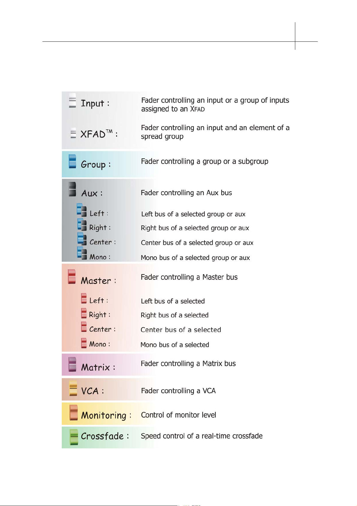
1.C The assignable functions
Each of the console faders can handle the following functions:
INTRODUCTION 1-3
User Guide - © InnovaSON - January 2004
Page 10
1-4 INTRODUCTION
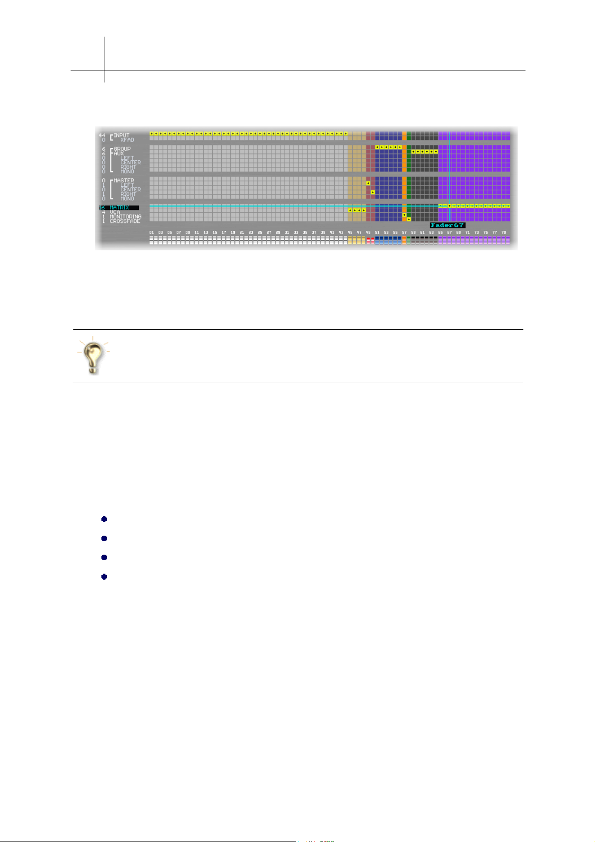
Each of the console faders can handle the following functions:
The number of faders available in this grid corresponds to that available on the console (shown here is
the Sy80). The Grid functions in the same way for any console as long as it supports Sensoft 8.1.
Later on in this manual we will show you how to access and use the configuration grid.
To give you the time to fully understand and master this feature, preset configurations
allow you to quickly set the parameters of your console. Having first inserted the floppy
disk “Examples”, use the Import function to load these standard configurations.
1.D Spread zones
Let’s take a few moments to consider the concept used by InnovaSON to exploit more physical inputs
and mix busses than there are faders on the console, without having to resort to a system of layers.
As you saw previously, InnovaSON designs consoles dedicated to, among other situations, live
applications. It was therefore important to establish a design that took note of the following points:
A console with a size and weight lower than its analogue counterpart
Retention of the user-friendliness inherent in software previous to Sensoft 8.1
To always have a global view of the general state of the console on the monitor screen
To have to hand the maximum number of controls, for fast and effective user reaction
This last point made InnovaSON decide to implement the X
8.1.
Whether for the management of inputs or the management of busses, the general principle is the
same: a full channel can control a single physical I/O or of a set of physical I/O. In the latter case, the
channel can be compared to a “fader bank”, because every time it is selected, it spreads out all the
channels it controls, in a zone defined by the user.
FAD function in the development of Sensoft
User Guide - © InnovaSON - January 2004
Page 11
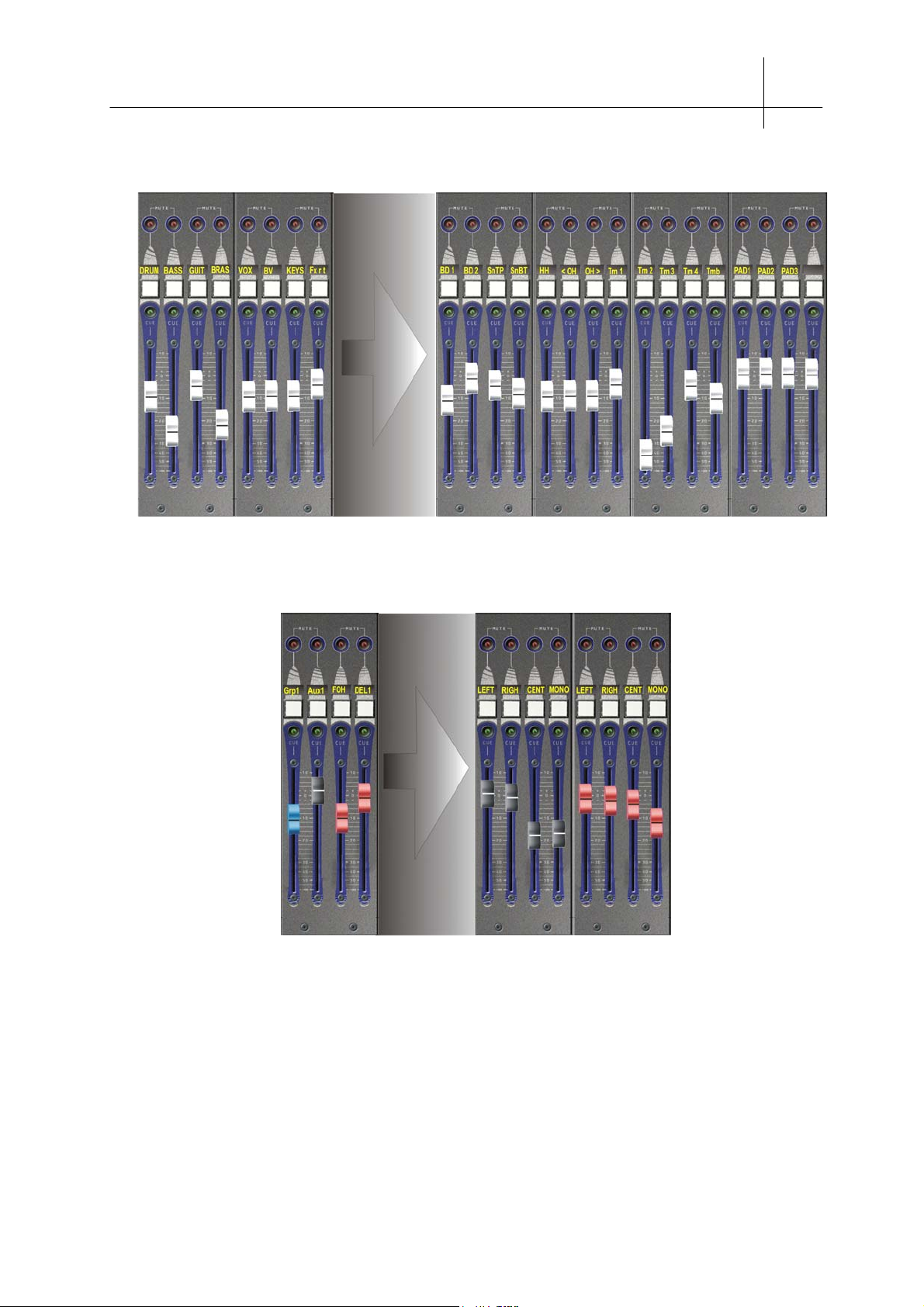
The principle of spread channels
y
r
INTRODUCTION 1-5
The channels associated with
one, or a group of, physical inputs
In the same way, Aux, Group or Master channels can spread thei
L, R, C and M busses if necessary, in this case you can compare
them to “Bus Banks”
The spread zone as defined by the user, made
up from as many X
FAD as neccessar
The figure above shows an example of 8 “banks”, each spreading 16 XFAD inputs. A swift calculation
shows that, in theory, you could control 8 x 16 = 128 inputs with only 8 + 16 = 24 faders…….what a
dream!
One of the major points of Sensoft 8.1 is that the number of “banks", and their arrangement as well as
the number of channels spread by the "banks", is defined by the user. Each user can effectively "draw"
the console according to their own needs.
User Guide - © InnovaSON - January 2004
Page 12

Page 13
2 THE Sy48 CONSOLE
2.A Sy48 : Overview of the product
The Sy48 console is a single block, 'all in one' system, with the
local Mix Box and the control surface within the same frame.
The Mix Box provides 6 slots for housing modules of 8 inputs or
8 outputs (analog, digital AES or Ethersound). Its modular
structure lets you configure the inputs and outputs according to
your needs. Hence, when used by itself, it can be equipped as
shown below, with 32 mic/line inputs, 16 line inputs, 16 analog
outputs with processing, and 16 line outputs.
THE Sy48 CONSOLE 2-1
32 mic/line inputs: SI-8D3 cards 16 line I/O 16 processed outputs: XO-8D2
The platform features everything you expect from a digital mixing console in a particularly compact
frame weighing less than 40 kg, including :
48 motorized and assignable faders with immediate access to the main parameters (selection,
monitoring and mute)
48 LED bar-graphs for immediate metering of input or output signals
A section for adjusting all the parameters of the current selected channel
A section for managing memories
A collapsible 12" screen for real time visualization of all the mix parameters
An access panel to all the main functions (patches, monitoring, talkback circuit, …)
A PC computer handles everything in the system
A keyboard/track-ball drawer for labeling and access to advanced functions
Space reserved for the local audio rack, where the I/O modules, the MC-64 controller and the DSP
Sy48 module can be found.
The digital aspect of the console is managed by the MC-Optical controller module, which generates
the audio clocks, drives the bus, and handles communications with the console’s integrated PC. This
module is equipped with BNC and optical connectors dedicated for the connection of a Stage Box,
which then allows the remote management of 48 Mic/line inputs and up to 32 mix busses. Therefore,
the slots of the local Mix Box can be equipped with more output modules, which leads to a maximum
of 6 analog or AES output modules, plus the 16 line outputs available on the SubD25 connector… that
gives us a total of 64 local outputs.
User guide - © InnovaSON - January 2005
Page 14
2-2 THE Sy48 CONSOLE
r
Coaxial or optical cable transmission is not an option. Every InnovaSON platform is equipped with this
transmission system. No need to invest in any format converter or other hardware to establish a
connection between a Stage-Box and the Mix-Box. Just connect the MCoptical (card featured in the
local rack) to the SCoptical (card featured in the remote rack) to immediately benefit from a digital
transmission, where 64 channels can be exchanged between both audio racks..
In the local audio rack, on top of the MC
controller, one
OPTICAL
can find the DSP (digital signal processor) Sy48 module, which
handles the digital processing of signals, and all the algorithms
that the console functions may use. This module is equipped
with 4 Sub-D 25 connectors which can manage 16 inputs and 16
outputs of line level signals,
which therefore add up to the resources
provided by the I/O cards of the rack. Four Sub-D /
XLR adapter cables are provided with the console.
The firmware currently available in the DSP Sy48 card provides simultaneous mixing of 64 inputs (48
Muxi + 16 line inputs) to 34 mix busses (two of which are reserved for stereo monitoring). The mix
busses have no predefined functionality. It’s up to you to use them as groups, sub-groups, auxiliaries,
masters, matrixes, …
The inputs/outputs accessible via the SubD connectors can be used as line inputs o
mix bus outputs, bus also as Insert Send/Return pairs to insert external processors.
As with any InnovaSON console, once the input and output cables are connected to their designated
devices, you no longer need to touch them. All patching operations are done electronically and are
memorized – all of which is managed directly from the control surface.
The Control Surface is relatively easy to understand; even beginners will rapidly feel at ease with the
digital mixing provided by the Sy48.
The various console channels are equipped with motorized faders which move into position rapidly,
quietly, and even feature a “sensory point” that can be felt under your fingers. Therefore, you always
have the last memorized position in mind.
The bar-graphs located just above the faders provide direct metering of various working levels, after
processing (dynamics, EQ) or before processing (reflecting the output level of the pre-amps),
depending on the option selected in the general preferences.
User guide - © InnovaSON - January 2005
Page 15

THE Sy48 CONSOLE 2-3
Last but not least, as soon as the console is switched on, the flat
LCD screen displays the main mix window or, depending on
preference settings, the other control windows of the platform. The
internal computer drives the DSP in real time according to the
actions taken by the user on the control surface. If necessary, the
console’s internal PC can be removed and replaced by the external
PC connection kit. You can therefore control the platform from any
PC on which Sensoft has been previously installed.
To make things easier in a given situation, provision has been made to replace the internal flat screen
by another SVGA standard screen. The keyboard and mouse can also be relocated (or replaced) by
removing them from their drawer.
2.B Personalization, options
Each system, within certain limits, can be adapted to the latest performances and options of the
InnovaSON range of products.
For this, please contact our authorized technical services for specific updates: DSP resources,
Sensoft, advice, etc
2.B.1 L.E.M : optional External Mix Box
In certain situations, it could be more practical to access the audio cards without having to go around
to the back of the console. In these cases, The L.E.M. option (for Local External Mixbox) is the
solution. You also benefit from 8 slots instead of the 6 inside the console.
The L.E.M. is equivalent to the Sy48's internal audio rack, except it is located outside of the
console. All the modules that would normally be fitted in the console's internal rack are 100%
compatible with the L.E.M.; no updating of the card is necessary to use the L.E.M.
The L.E.M. is the same local audio rack as the one used by the Sy80 platform. Therefore, you must
follow the same rules concerning the location of the audio cards within the rack:
Always start by the output cards (XO, MO, DO) and then finish by the input cards (SI, DI), if you
are using any.
The Stage-Box (is you are using one) will follow the inverse rule: first the input cards, then the
output cards. Don't forget that the cards with the Hyperdrive option (XO-8D2, DO-8X, DO-8Xes)
do not work in a Stage-Box. Only the MO and DO-8A are designed to work in a Stage-Box.
User guide - © InnovaSON - January 2005
Page 16
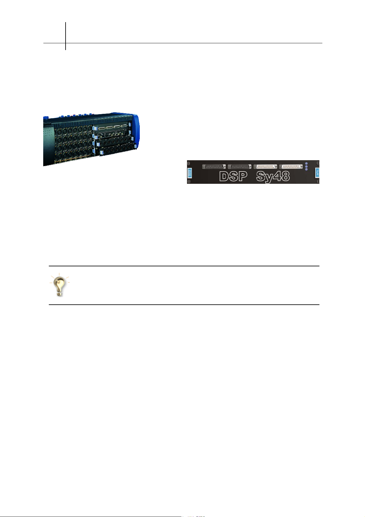
2-4 THE Sy48 CONSOLE
f
MC
OPTICAL
DSP Sy48
Output cards
Input cards
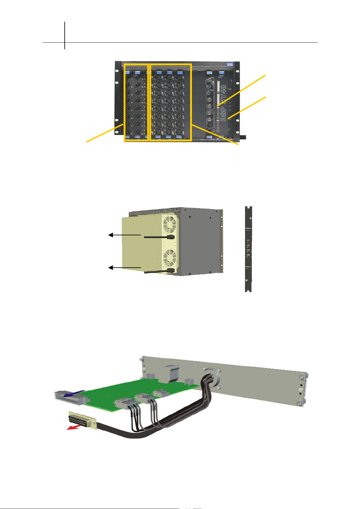
A standard SG3100 audio rack is equipped with two internal power supplies, with automatic
switchover if a problem was to occur on one of them. For the automatic switchover to function
properly, it is imperative that both power supplies of the rack be connected to the mains.
The PSU module, in the last
Power supply A’s
connection to mains
position in the Audio Rack,
indicates the state of the two
internal power supplies.
Power supply B’s
connection to mains
Connection to the console
Blank face plates are used on the integrated audio rack on the back of the console. They are placed in
the audio and MC cards position. One of these cards, the DSP Sy48, is replaced by the SF2077
module, which is a Jeager adapter enabling the connection to the external Mix-Box.
To the DSP connector of
the console's internal rack.
To the SubD25 connector o
the console's internal rack.
User guide - © InnovaSON - January 2005
Page 17
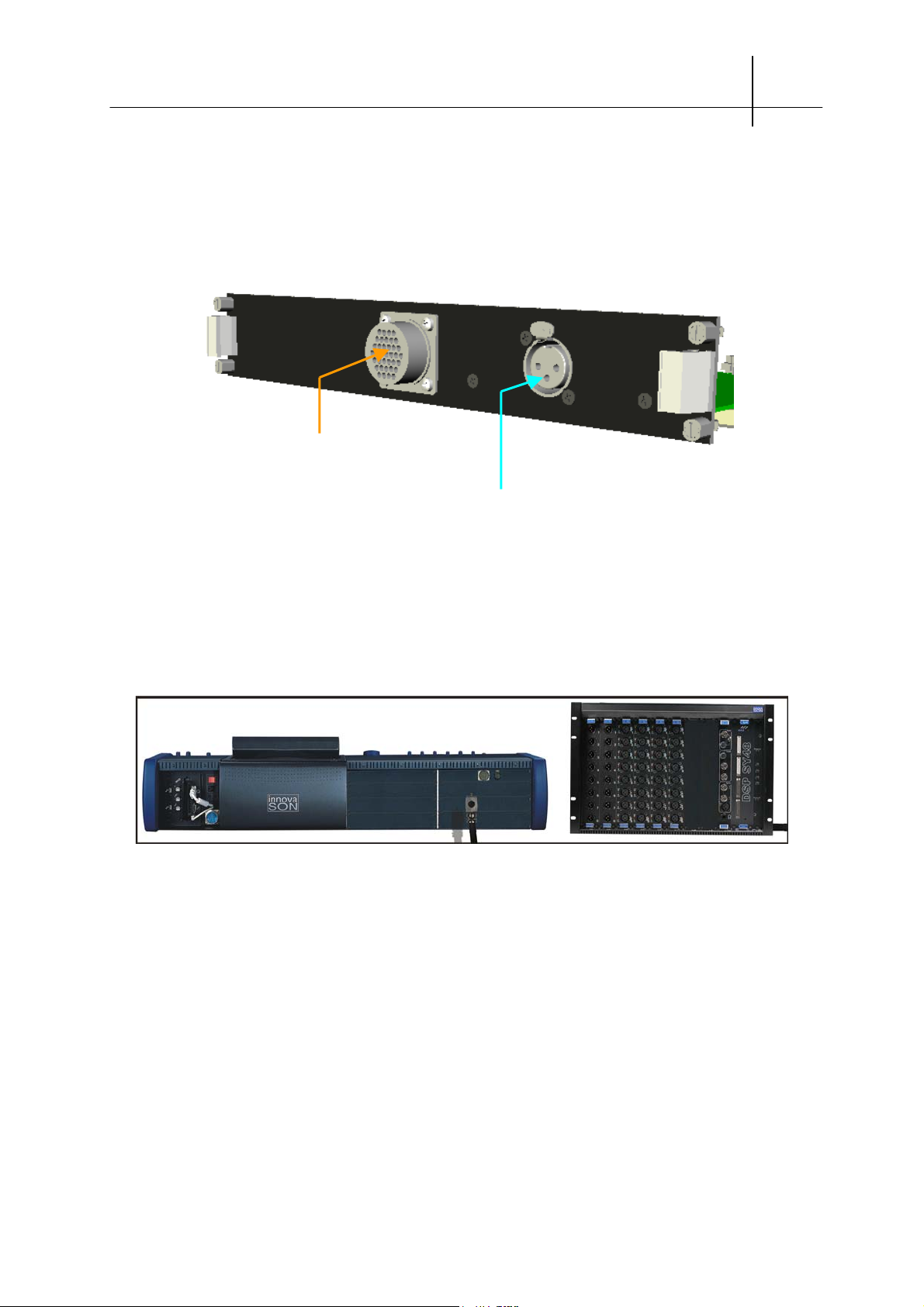
THE Sy48 CONSOLE 2-5
The SF2077 module is inserted in the DSP slot and a cable, linked to the module's Jaeger connecter,
must be plugged and secured with two screws on the SubD25 connector, at the base of the rack.
Initially, this connector would receive the MC
The SF2077 module (front view)…
Connection of the Jaeger cable
link to the L.E.M.
XLR connector for talk-back mic.
's SubD25 connector.
OPTICAL
The L.E.M. is supplied with a 5 meter long Jaeger cable. Just connect the cable between the console
and the audio rack before powering-up the system…
CONNECTION OF THE L.E.M. TO THE CONSOLE
User guide - © InnovaSON - January 2005
Page 18
2-6 THE Sy48 CONSOLE
2.C Description of the Sy48
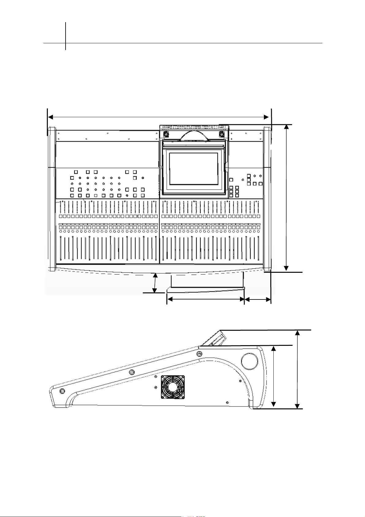
2.C.1 Dimensions and general information
1152,7mm / 45,4’’
155mm / 6,1’’
401mm / 15,8’’ 132,9mm / 5,24’’
1150 mm
771,2mm / 30,37’’
213,2mm / 8,4’’
334,1mm / 13,16’’ max.
User guide - © InnovaSON - January 2005
Page 19

THE Sy48 CONSOLE 2-7
Console :
Length: 1152,7 mm / 45,4’’
Width: 771,2 mm / 30,37’’
Height: 213,2 mm (screen folded down), 334,1 mm maxi. / (8,4’’ /
13,16’’)
Weight: 40 kg by itself (88 Pounds)
Shipping crate: 1300 x 450 x 900 mm, 90 kg / 51,2’’ x 17,7’’ x 35,4’’, 198
Pounds.
Power supply: 90/253 Vac, 46 to 63 Hz
Power consumption: 300 VA max
Working temperature: +10°C to +35°C (50 to 95 °F)
Faders: 48 motorized 100 mm ALPS faders
Labeling: 48 4 character LED Matrix
Control: 141 switches, Cue, Select and Mute per fader
Bar-graphs: 48 Vu-meters (16 LED)
Pots: 23 rotating encoders for audio parameters and console control
Switches: 34 switches for audio functions and global control
Internal computer: PC Compatible, Pentium 1GhZ, 128 Mb of RAM
Screen: 12" collapsible flat LCD screen
MIDI card: InnovaSON
Keyboard: CHERRY ML4100 QWERTY (keyboard + track ball)
Backup: On any USB storage device (3 available ports) 3”1/2 USB)
Hard disk: 128/256 Mo Flash Memory
Rack audio Stage-Box (optional) :
Length: 482 mm (19’’)
Width : 325 mm (12,8’’)
Height: 312 mm (7U, 12,3’’)
Weight : 20 kg by itslef / 44 Pounds
75 kg with shipping crate / 165 Pounds
Basic modules: 1 SC
controller module and 1 SI-8D3 module
OPTICAL
Coaxial cable: 2x150m, 75 Ohms, 4 BNC, supplied on a drum
Shipping crate: 800 x 640 x 740 mm / 31,5’’ x 25,2’’ x 29’’
L.E.M. audio rack (optional) :
Length : 482 mm (19’’)
Width : 325 mm (12,8’’)
Height: 312 mm (7U, 12,3’’)
Weight : 20 kg by itself / 44 Pounds
75 Kg with shipping crate / 165 Pounds
Basic modules: 1 MC
controller module
OPTICAL
Shipping crate: 800 x 640 x 740 mm / 31,5’’ x 25,2’’ x 29’’
User guide - © InnovaSON - January 2005
Page 20
2-8 THE Sy48 CONSOLE
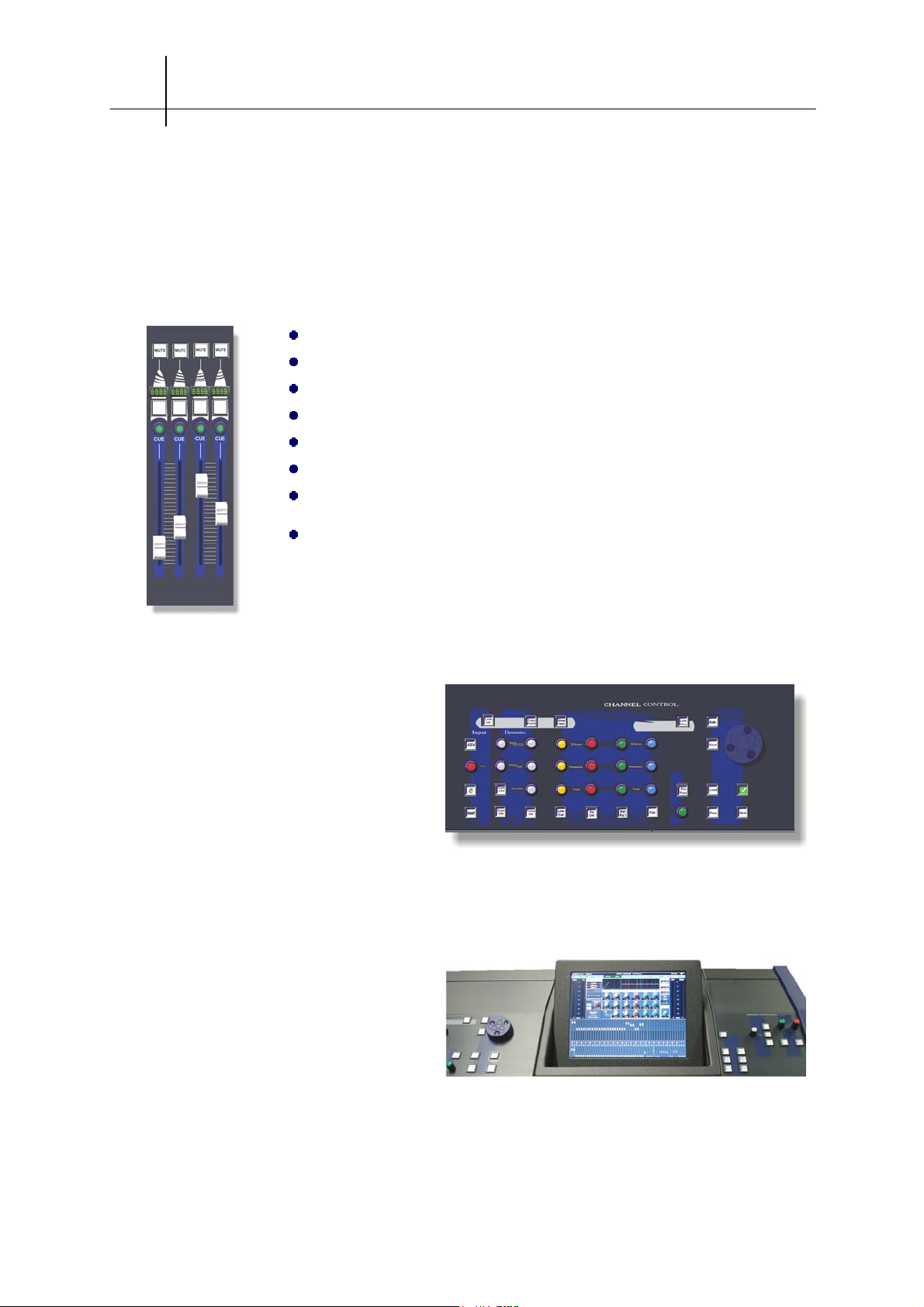
2.C.2 The Quadfad module
A Quadfad module features 4 motorized faders. Each fader has its own 4-character label. The 12
Quadfad modules of the console are identical. Sensoft lets you determine the purpose of each fader.
Their presence is automatically detected by Sensoft.
The main characteristics of a Quadfad module are as follows :
ALPS 100 mm motorized fader
8 bit linear conversion for servo-control and fader positioning
nominal positioning time: 100 ms
Sensory memory of stored fader position
Illuminated switch to indicate Channel selection
Illuminated [CUE] switch (green) to indicate assignment to the Monitor bus
Illuminated [MUTE] switch (red)
4-character Labeling display (adjustable highlighting / for when the channel
is selected)
2.C.3 The CHANNEL CONTROL panel
Integrated within the console frame, and
ideally positioned to be accessed rapidly, this
panel centralizes all the channel's parameter
controllers (gain, EQ, Dynamics section,
etc…). Pan control, and amongst other things,
access buttons to the various 'LIVE' functions
such as Copy, OverRam, and the patch
windows, are also found on that panel.
2.C.4 Screen and UTILITIES panel
Three sections complete the access to the
console's functions with, from left to right, the
page and show management panel, the
central screen to visualize the current mix, and
the patch grid, monitoring circuit management
and talk-back mic panel.
User guide - © InnovaSON - January 2005
Page 21
THE Sy48 CONSOLE 2-9
pply(
)
A
On top of the screen, you will find three small holes that let you adjust
brightness and other settings. A user manual for the screen is supplied
with the console to guide you in the procedure. In any event, one of the
configuration menus offers an automatic adjustment, which will
optimize settings according to the video signal' characteristics.
During the console's startup procedure, the image may be unstable. This is perfectly normal. As soon
as Sensoft is launched, the image will be stable.
2.C.5 On the front of the console
Left of the keyboard drawer, you will
find 3 connectors:
- A 1/4" headphone jack
- An XLR connector for a talk-back mic
- A USB connector for any storage
device
Volume of the headphone jack can be adjusted with the [Level] pot of the monitor section
when no other monitoring circuit is active
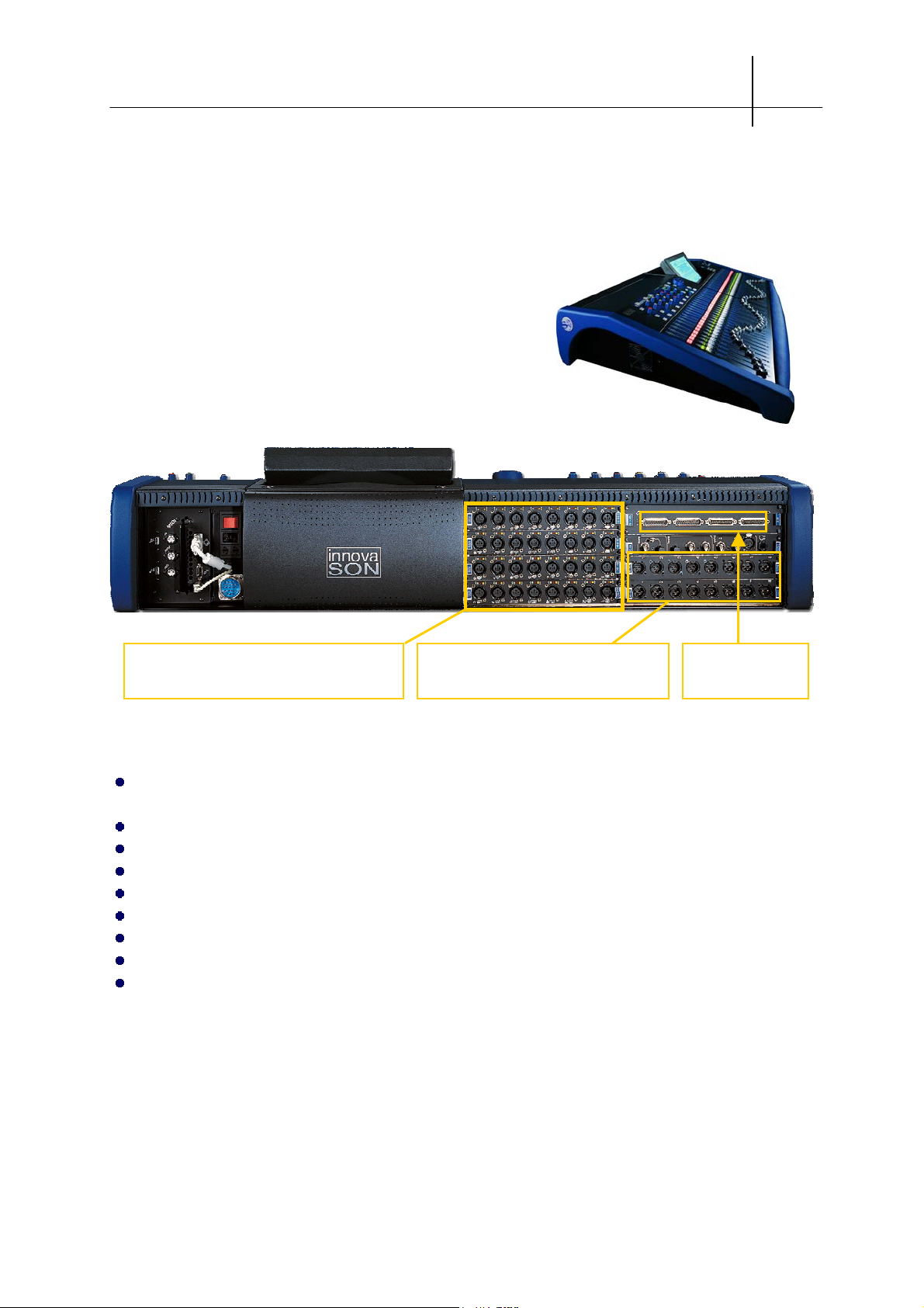
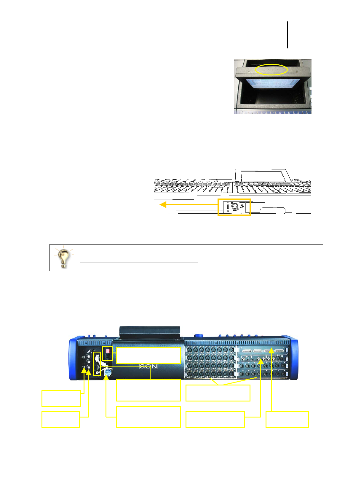
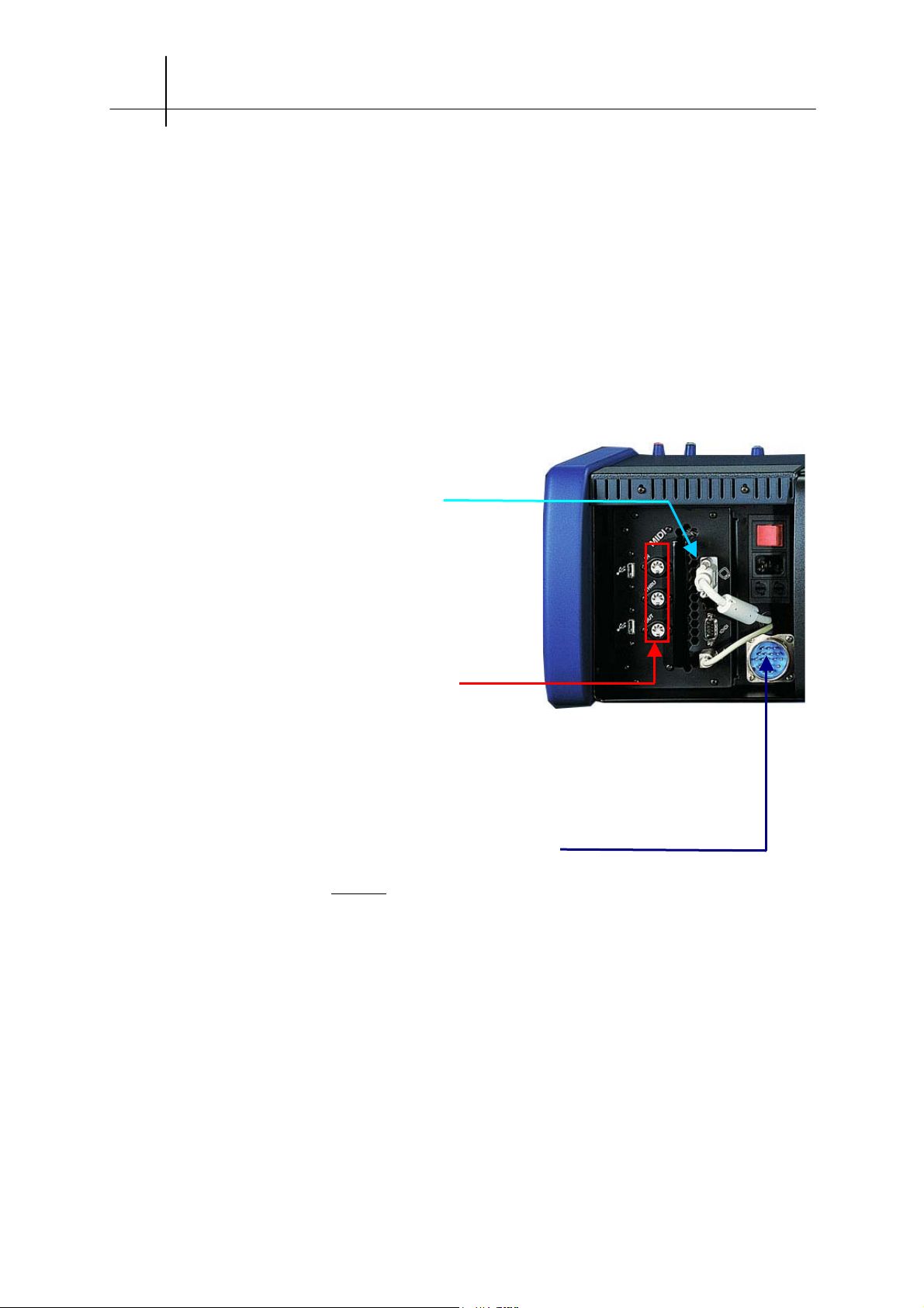
2.C.6 On the back of the console
Mains connector and main
power switch
Keyboard, track-ball, VGA
2 USB
connectors
MIDI
conections
screen connections
Connection of an autoredundant external power
SV0038
su
.
vailable slots for local
audio cards
MC
transmission card
OPTICAL
control and
DSP card and line
I/O
User guide - © InnovaSON - January 2005
Page 22
2-10 THE Sy48 CONSOLE
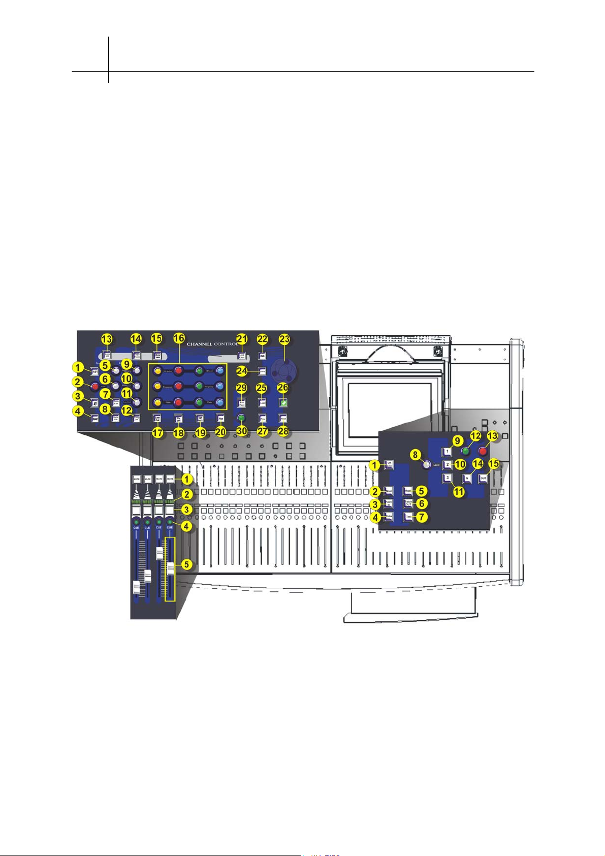
2.C.7 Control layout
Channel control panel
Control surface layout
Faders section
Monitor/Utilities panel
User guide - © InnovaSON - January 2005
Page 23

THE Sy48 CONSOLE 2-11
A
y
The Channel Control panel The Monitor/Utilities panel
I
1-On/Off Alimentation phantom
1-Phantom power On/Off
N
2-Gain du pré-ampli micro
2-Mic pre-amp gain
P
U
3-Inversion de phase
3-Phase inversion
T
4-
4-Insert return In/Out
ctivation/désactivation Insert Return
5- Attack parameter control
6- Release parameter control
D
7- Gate / Compressor settings toggle
Y
N
8- Noise Gate On/Off
A
9- Threshold parameter control
M
I
10- Range parameter control
C
11- Hold parameter control
S
12- Compressor On/Off
13- I/O card parameter link
T
14-Copies a channel's parameters
O
15-Propagates the parameter values to
O
L
the other pages in RAM
S
20- Initialization of Eq, Dynamics, …
21-Mix parameter link
16- Digital EQ's parameter controls
17-Low-cut filter On/Off
E
18- EQ On/Off
Q
19-Toggles between the first 4 and last 4 EQ
bands of the Hyperdrive cards (XO, …)
22- File edit window
F
I
23- Rotating encoders: lets you navigate
L
through lists, grids, …
E
S
24- Saves the current page
/
25- Loads a folder from the Hard disk to the
N
A
RAM
V
26- Confirmation: OK key
I
G
27- Previous memory
28- Next memor
29- Aux parameter window: Pre/Post,
P
independent Pan, routing…
A
30- Pan placement adjustment (Hyperdrive
N
card output level in Muxi mode).
1- OffLine : désolidarisation de la console
1- OffLine : Disconnects the console from
des racks audio. Permet d’éditer pages
the audio racks.
et paramètres de mixage sans affecter
2- Muxi : Visualization of the system's
l’audio en cours.
outputs.
2- Muxi : fenêtre de visualisation de
3- Input patch grid
U
U
T
T
toutes les sorties du système.
4- Switch to « manual » for selected
I
I
3- Grille de patch des entrées
parameters in selected channels
L
L
I
I
4- Mise en « manuel » des paramètres
5- Request : Visualization and rapid
T
T
I
I
sélectionnés pour les tranches
activation of Phantom power, LowCut,
E
E
sélectionnées.
EQ, …
S
S
5- Request : Visualisation et activation
6- Output patch grid
rapides des alims Ph, LowCut, Eq,…
7- Test : settings and activation of the
6- Grille de patch des sorties
test oscillator.
7- Test : paramétrage et activation de
l’oscillateur de test.
8- TB mic or active monitoging circuit
level (depending on general pref.)
9- TB 1 or Monitoring circuit 1
(depending on general pref.)
M
10- TB 2 or Monitoring circuit 2
O
N
(depending on general pref.)
I
11- TB 3 or Monitoring circuit 3
T
O
(depending on general pref.)
R
I
12- Level control when monitoring inputs
N
13- level control when monitoring mix
G
busses
14- IN : Toggles input monitoring
between PFL and AFL
15- OUT : Toggles mix bus monitoring
between PFL, AFL and APL
The Faders section
1- Channel mute
C
H
2- Channel label
A
3- Selects this channel's parameters
N
N
4- CUE: sends the Channel to the
E
monitoring bus.
L
5- Channel fader
User guide - © InnovaSON - January 2005
Page 24

2-12 THE Sy48 CONSOLE
2.D Precautionary measures, safety and warnings
Read this section carefully in order to use the control surface safely.
1.Never connect a receiver (camera) that has its own phantom power activated: this
would destroy the output to which it has been connected. Switch the phantom power
off, or if this is not possible, go through an external device first (isolation transformer,
intermediate pre-amp, etc…).
2. Only the swapping of presumably defective modules is advised, and made possible by
the modular philosophy of the control surface.
ANY SWAPPING OF MODULES MUST BE DONE WITH THE CONSOLE SWITCHED
OFF.
3. Do not store or use the console in extreme temperature conditions, or in an
environment where it might be exposed to vibrations, dust or humidity.
4. Never use any liquid to clean the surface of the console (ideally, use a soft and dry
cloth). Only use water or ethylic alcohol to clean the casing and silk-screen printed
surfaces; other solvents could damage the paint or plastic parts.
5. Do not place the audio racks, local or remote, or the console itself, too close to strong
electromagnetic radiation sources (video monitors, high-voltage cables, …), as this
might cause a degradation of audio quality via induced currents in the connections
and frame.
User guide - © InnovaSON - January 2005
Page 25

THE Sy48 CONSOLE 2-13
2.E Manipulation and transport
Before you move the console, make sure that
everything is disconnected. Never put excessive
pressure on the pots, switches and connectors.
The Sy48 console provides two grips under the
plastic flanks on each side, for easy maneuvering.
2.F Power supplies and EC standards
The Sy48 console may be powered by any voltage ranging from 90 et 253 Volts AC / at 47-63 Hz.
The power supply must be earthed.
For optimal performance, it is essential that the earthing network be free of noise, since all signals are
going to be referenced to it. A central point must therefore be determined as the main earthing
connection, and all other earthing connections must originate from that point. It is recommended that
you pull an extra earthing wire from each socket, wire that will be directly connected to the central
earthing point: this is the best way to ground all the devices of your installation.
When the console is in use, do not block the cooling vents. Be especially careful of that if you are
using the console while it remains in the lower half of its flight-case.
For electrical precautionary measures, please refer to chapter 10 - Appendices
2.G Connections
Connections to the control surface are reduced to a minimum for easy installation, and an increased
reliability of the system. To use an external PC (desktop or laptop) you will need accessory SG9008
which will replace the internal PC, with connectors provided for hooking-up the external PC.
2.G.1 Audio connections
The Sy48’s platform connections are all standard and were chosen to correspond with the most
widespread in the professional live audio industry. No need to buy extra adapters or specific
connectors when using the console in a normal environment. If, however, you have specific needs,
feel free to contact InnovaSON’s technical service. The contact information can be found on our web
site and at the end of this manual.
Do not connect other audio devices which are switched on, before you power up the console. The
Sy48 is a computerized platform which starts up in the last saved statuses, that you do not necessarily
know. Unknown parameters relative to gain settings, or output levels, could damage various audio
equipment (power amps, speakers,…), or even cause hearing damage to people too close to the
speakers. Good practice would be to always shut down the console on a blank page, in which all the
settings would be zeroed.
,
User guide - © InnovaSON - January 2005
Page 26
2-14 THE Sy48 CONSOLE
2.G.2 Interal screen, external screen
The standard screen housed in the console is a collapsible color LCD flat screen. The collapsed
position is used during transportation. The screen can be tilted to suit your viewing position. A user
manual for the screen is supplied with the console.
With a stylus, the holes on top of the screen's plastic casing give you access to the brightness, color
and contrast settings.
Instead of the integrated screen, you can use any other standard SVGA monitor. Pay particular
attention to the electromagnetic radiations that could appear when using a CRT (Cathode Ray tube)
monitor.
The screen’s connector is linked to the internal computer, on
the rear of the console. If you are using an external
computer, the screen (built-in LCD or other) can be quickly
connected to the current working computer.
2.G.3 Connecting MIDI equipment
The Sy48's MIDI connectors are located on the internal PC,
at the rear of the console: they will accept any MIDI compatible device. To make sure your
connection will work, always use a cable that complies with MIDI specifications. Sensoft
provides a utility tool for testing MIDI cables: refer to section 8.
2.G.4 Connection of an external power supply
An external power supply unit SV0038 can be connected to the console to provide backup to the
internal power supply in case it fails. It is even possible to connect two external power supplies, and
control the power-up of the console remotely from them.
Contact our technical services for further information on that matter.
The Jaeger connecter dedicated to connecting an external power supply is equipped with a protection
cap that MUST be in position when this function is not used. The cap keeps any short circuits from
occurring between the Jaeger connector's pins.
2.G.5 Connecting an external PC
Any IBM-PC compatible computer, hosting a processor of at least 800MHz with 64Mb of
RAM can be used to supervise the operation of the console instead of the internal unit. The
SG9008 accessory is necessary for this type of operation. While on tour, we more than
recommend that you purchase this accessory and keep a laptop PC ready, to "save the day".
User guide - © InnovaSON - January 2005
Page 27
THE Sy48 CONSOLE 2-15
p
r
p
g
p
The Windows XPE operating system installed in the console’s internal PC is an XP core
assembled by InnovaSON developers, in order to contain only the required elements
necessary for managing the Sy48 platform. This is a mandatory condition to guarantee a
stable, crash free, system. InnovaSON can not be liable for the instability of the operating
system installed on your personal computer, connected to the platform. Our technical support
is always ready to help you configure your computer for such a use.
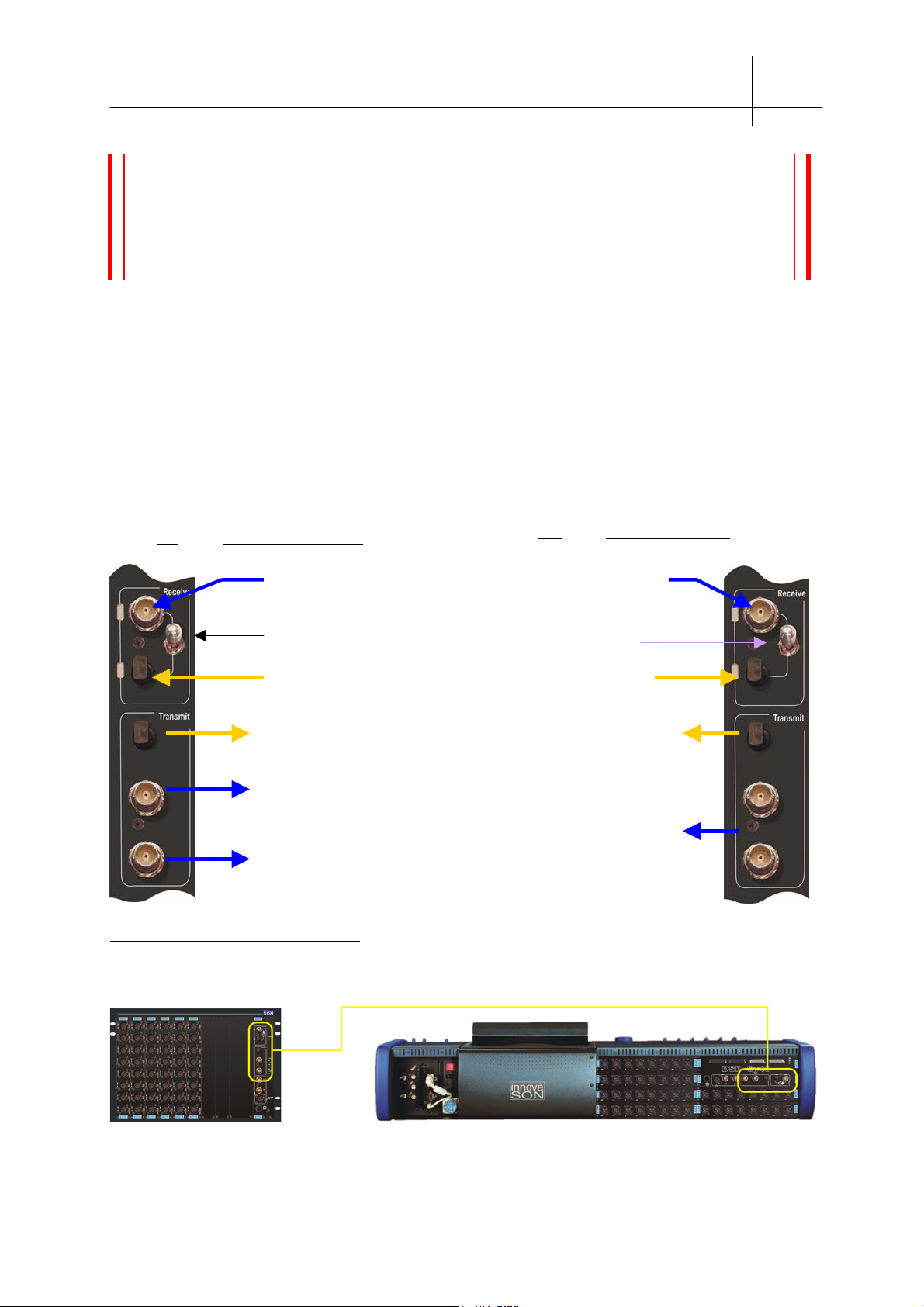
2.G.6 Connecting an optional Stage-Box
The MC
OPTICAL
and SC
cards, supplied as standard with the Mix-Box and Stage-Box, have their
OPTICAL
own coaxial and optical transmission system. It is very easy to initiate this transmission, as shown in
the diagram below. The link may be uni or bi-directional. If it is uni-directional, only one TX of the
Stage-Box will be linked to the RX of the MC. In this case, the console is in « Slave » status and
cannot control the gain and PH48V of remote microphone input cards.
We must insist on the need to use good quality cables or fibers and to take particularly good care of
the connections used for this link.
SC
: on the Stage Box
OPTICAL
Control signals coming from
the MC via a coaxial cable.
Selection of the optical or
coaxial in
Control signals coming from
the MC via an o
Transmission of 64 audio
channels to the audio rack’s MCs.
The three links work in parallel,
so the sources (mics or other)
can be split digitally to 3
platforms.
ut
tical fibe
MC
OPTICAL
Reception of the 64 channels
from the SC via Coax.
comin
Selection of the optical or
coaxial in
Reception of the 64
channels coming from the
SC via fiber.
Control of a Stage Box, via its
optical or coaxial input. The third
coaxial link may be used as a
backup for the second one…
ut
: on the Mix Box
Several configurations are possible:
Up to 500m coaxial or optical
6 SI-8D3 : 48 remote
mic/line inputs
User guide - © InnovaSON - January 2005
- 6 XO-8D2 : 48 processed outputs
- 16 outputs accessible on 2 Sub-D connectors
- 16 line inputs accessible on 2 Sub-D connectors
Page 28
2-16 THE Sy48 CONSOLE
Up to 500m coaxial or optical
6 SI-8D3 : 48 remote mic/line inputs
2 MO-8D3 : 16 analog outputs
- 4 XO-8D2 : 32 processed outputs
- 16 outputs accessible on 2 Sub-D connectors
- 16 line inputs accessible on 2 Sub-D connectors
Nothing is easier than adapting the console to your needs, whether you are using it for monitoring,
Front of House, theatre, opera, broadcast…
The only limitations are:
No similar type cards (input/output) on the same remote and local slots (A, B, C,…).
Maximum simultaneous mixing of 48 Muxi inputs (inputs coming from SI and DI cards) plus the 16
line inputs of the DSP card (Sub-D). These 48 Muxi inputs can be selected, for each page of the show,
amongst the 64 possible inputs.
Maximum transmission of 32 busses to the Stage-Box, patchable on 4 MO-8D3 or DO-8A cards.
These cards must imperatively be installed in slots E, F, G or H of the Stage-Box.
Using remote output cards condemns the use of input cards installed on the same local slots.
Please refer to the Sensoft 9.1 Addendum for further detail.
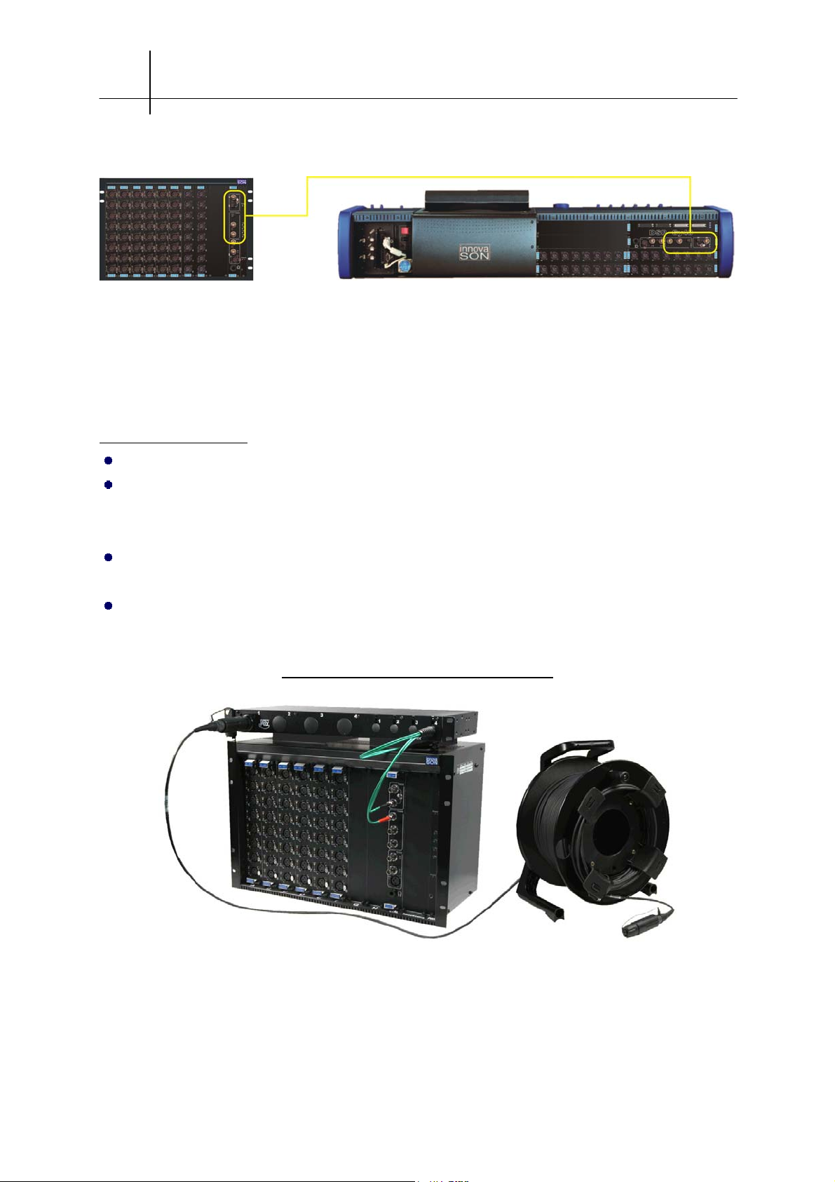
Example of a Stage Box and its optical fiber
Also refer to section 9 for the rules concerning the use of the Stage-Box.
User guide - © InnovaSON - January 2005
Page 29
THE Sy48 CONSOLE 2-17
2.G.7 Digital audio clock sync with external devices
There are several ways to sync the digital audio clocks of external devices with InnovaSON’s platform
clock. This can be done through SRC (Sample Rate Converter), on one or several digital audio inputs
or via a Word-Clock or AES link, to synchronize the entire system to the same clock source.
Principle of the SRC (real-time sample rate conversion) :
This allows each equipment to keep its internal digital audio clock source. The digital inputs (AES or
other) is immediately followed by a SRC algorithm allowing the synchronization of the incoming
sample rate to the one used by the receiving system. The conversion has a range of about 10%
around the sample rate of the receiving system. The DI-8SRC
an algorithm. Each one of the card’s 4 AES inputs can receive an external digital audio signal with a
sampling frequency between 32 and 50 KHz. The card output is itself synchronized to the global clock
rate defined in the InnovaSON platform.
This feature has the advantage of letting you connect several digital audio sources to the console
without having to worry about syncing the sources to one another. Be careful: the SRC creates an
additional calculation latency, which leads to a non-negligible delay of up to 1.5ms in the « worst case
» conversion… Moreover, again for calculation reasons, the original 24 bit resolution at the SRC’s
input will be « reduced » to 20 bits after conversion… Rest assured: the audio quality is still very
InnovaSON card is equipped with such
good.
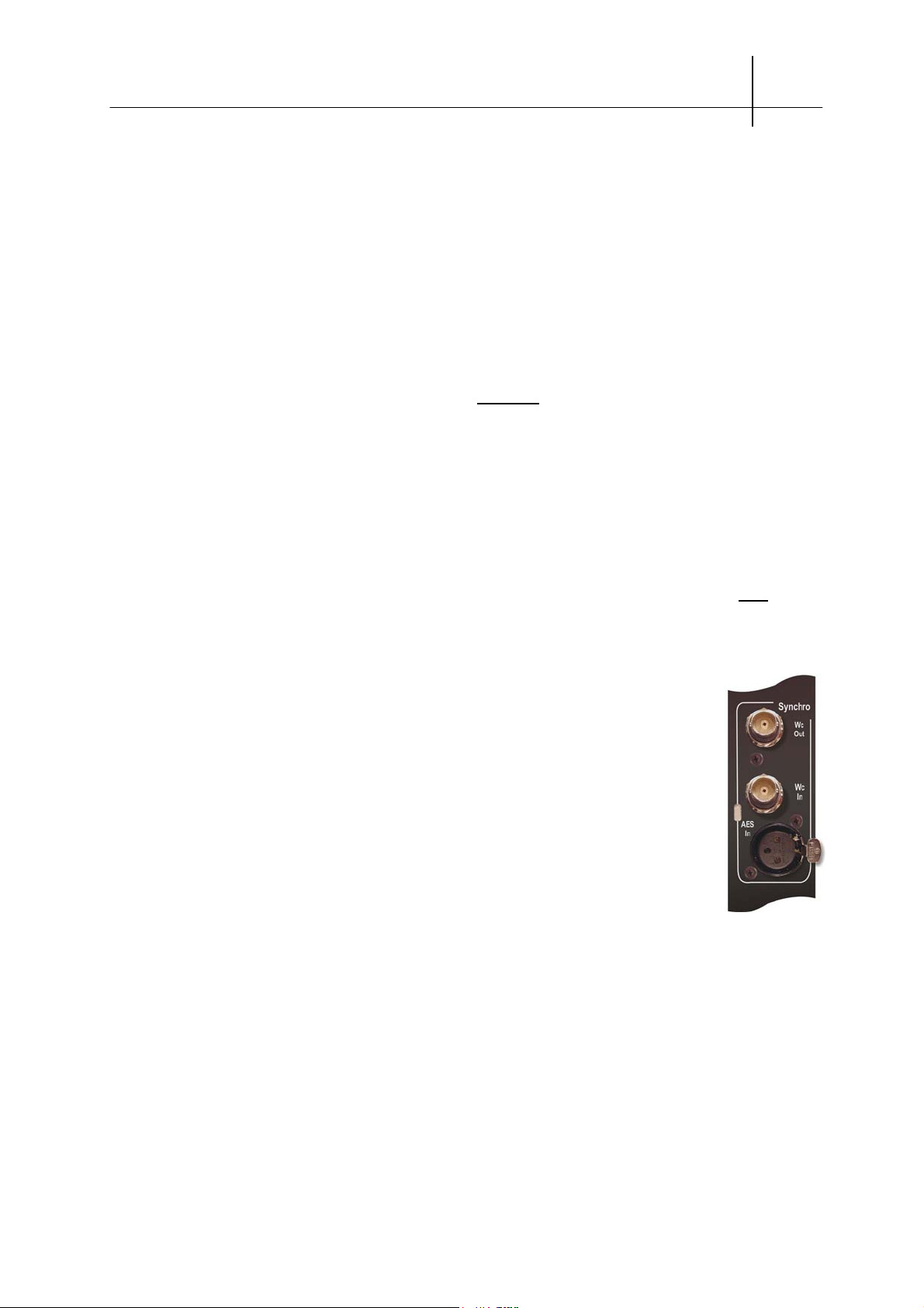
Using Word-Clock input and output :
When the console is meant to exchange a great number of digital input/outputs or is
integrated in a digital audio environment where all the machines are synced to one
another, it might be more useful to use the Word-Clok I/O of the platform. The console
can be used as the « master clock source » or be synchronized to a reference clock. In
the first case, just take the WC output of the MC and/or SC (if there’s a Stage-Box) and
distribute that signal to the WC inputs of the other devices. Note that the WC signal is
available both on the local audio rack and on the optional Stage-Box. If, on the other
hand, you wish to sync the console to a reference clock (48KHz), connect that clock
signal to the MC’s WC input. If you are also using a Stage-Box, then you MUST use
the WC input of that Stage-Box’s SC instead. The Stage-Box being the clock master for
the platform, it must be the one receiving the external clock signal. If you are using a
Stage-Box, the MC’s WC input is ignored (the L.E.D normally showing synchronization stays off).
Using the AES input:
The MC and SC cards also feature an AES input. When a digital audio signal is connected to this
input, the platform can extract the clocking information from the signal and sync to it. The same rule
concerning the Stage-Box applies here : always sync the Stage-Box if you are using one, not the MixBox.
User guide - © InnovaSON - January 2005
Page 30
2-18 THE Sy48 CONSOLE
A few cases where no external synchronization is necessary :
There are a few cases where it is not necessary to use any sync signal between the console and
digital audio devices. Indeed, when the console feeds a digital audio signal to a device for processing
purposes (effect, dynamic processor, digital recorder, …) which is then returned to the console after
processing, no need to use an SRC or a WC. Just configure the external device so it syncs on the
incoming AES signal (fed by the console). The signal supplied by the device’s output will also be
synced by the incoming signal, and therefore, to the console’s digital audio clock.
For signal exchange with digital outboard, it is therefore possible and even simpler to use DO-8 and
DI-8A cards without worrying about syncing devices with one another. This will be done by configuring
each outboard’s digital clock source.
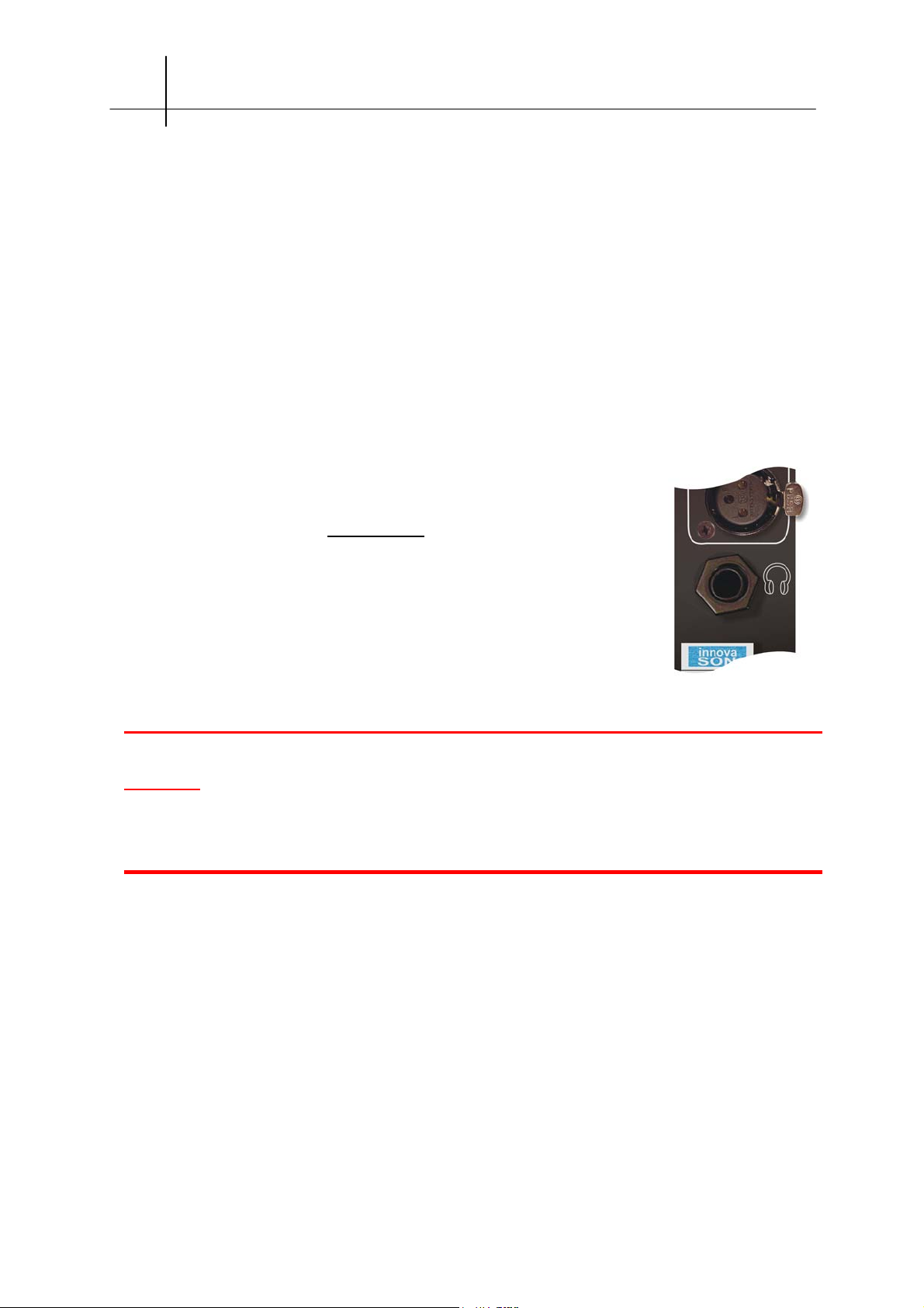
2.G.8 Connecting headphones
There are no restrictions to the use of headphones on the console’s
headphone connector (refer to section 2.C.5
not to use the MC card’s headphone jack, which goes way back in
InnovaSON’s history of developments! This output was originally designed for
monitoring functions of the Muxipaire, when no console was used. This output
does not feature a volume control.
). However, it is strongly advised
CAUTION:
operational only when using a Muxipair and when the card is configured as an MC and not as
an SC.
Do NOT connect headphones to the SC
‘s headphone jack. This jack is
OPTICAL
User guide - © InnovaSON - January 2005
Page 31

THE Sy48 CONSOLE 2-19
2.H Powering up
The Sy48’s elements must be powered up following these specific instructions. Failure to
do so might damage the equipment; some elements might end up being unusable.
2.H.1 Power up sequence
Mains connections
Connect the console's mains power cord, located on the back. The audio racks (L.E.M. and StageBox) require two power cords that must imperatively be connected to the mains for the power supply
redundancy system to function properly.
Before powering-up them up, make sure that the audio inputs and outputs are not connected to any
elements that might be easily damaged (amplifiers, headphones, ears, etc…).
If you are using a Stage-Box, you should switch it on first, sera mis sous tension en premier, for its
configuration to be automatically recognized by the console. Bad recognition will not give you access to
all the parameters, and will not allow active monitoring of the various working states of the system's
elements.
There is no power switch on the audio racks: you simply plug the two mains cords of its power supplies
to switch the rack on. No need to worry about any accidental shutdown.
Caution: respect as much as possible the power-up sequence below:
1. Power-up the Stage-Box (if you are using one)
2. Power-up the L.E.M. (if you are using one)
3. Power-up the console
When using a Stage-Box, you MUST connect the transmission cards with the provided
coaxial or optical cable (see paragraph 2.G.6).
The console, when used by itself, uses its internal clock source, and is « clock master ». With a StageBox, the system’s clock is provided and distributed by that audio rack. This is why, when using a
Stage-Box, only the WC and AES inputs of the SC
output both generate the same clock rate than the one provided by the Stage-Box.
are operational. The MC’s and SC’s WC
OPTICAL
The power-up sequence is important because it lets the Stage Box send the clocking signal on the
optical or coaxial cable first, so the connected MCs may sync to it as soon as they are switched on.
User guide - © InnovaSON - January 2005
Page 32

2-20 THE Sy48 CONSOLE
As soon as the rack is switched on, it is important to check that it is functioning properly.
The power supply card has 4 LEDs indicating the presence and conformity of the 4 secondary
voltages.
The MC
OPTICAL
and SC
modules feature, next to the RX connectors, a few LEDs. The input
OPTICAL
which has been selected with the switch should illuminate the corresponding LED in red, thus
indicating that the rack and its transmission card are both functioning correctly. It will turn green
as soon as the MC/SC communication is established. This should happen just a few seconds
after Sensoft has been launched. If the MC is not connected to a Stage-Box, the RX LED will, of
course, stay red.
In the console, two little cards indicate the state of the internal power supplies, LEDs slightly
sticking out of the plastic covers will provide readings of these states :
On the left, the LEDs regarding the audio section
red (+5V), green (+/-15V), yellow (+48V)
On the right, the PC and the control surface
2 red (+5V) and 2 green (+/-12V)
The start-up procedure should last about 30 seconds, during which a few messages and images
are displayed before Sensoft is finally loaded. If the startup fails, shut the power down, wait 20 to 30
seconds before switching the power back on. Even though the internal computer is very robust, a
power shortage during a backup can make an important file unreadable, therefore disrupting the
startup procedure. If this were to happen too often, back-up all your files and reinstall the System and
Sensoft (see section 8). If, in spite of this, the startup still causes trouble, contact InnovaSON’s
technical service.
The parameters that were last saved might be different from those necessary our required. Make
sure that step after step, all the parameters comply to your needs and to the rest of the audio
installation.
The elements of the sound reinforcement system may now be connected and switched on.
User guide - © InnovaSON - January 2005
Page 33

THE Sy48 CONSOLE 2-21
r
A
r
The console is now ready
It will be in the mix mode that was last used before it was shut
down (last recalled page). If you took care of shutting down the
console on a blank, inert, page, the console will boot in this
state. It is therefore recommended that your show contain an
inert end page (or start page), recalled and saved prior to
shutting down, which then means that powering up can be done
safely.
When using the console for the first time, the default elements are the INNOVA folder containing the
blank INNOVA page. A disk is provided with templates that you can import.
2.H.2 First checks
Before going further, it is important that you check some information with the screen :
LOCAL
The console is
autonomous. No data is
received from a StageBox. Communication with
the local audio rack (o
L.E.M.) is OK.
SLAVE
The console is receiving
data from a Stage-Box,
but the TX link has not
been detected. Therefore,
the console cannot control
remote mic preamps
MASTER
Indicates that both links
have been detected. The
console is ‘Master’ of the
system, and therefore
controls remote mic
preamps (gain and 48V)
and the potential channels
returning to the StageBox.
NO SYSTEM
bnormal situation on a
Sy48. The internal audio
rack (or the L.E.M.) has
not been detected by the
console.
The screen displays the faders in their exact position, their colors reflecting thei
associated functions.
The screen displays the various fader positions as well as the state of the mix parameters, such as the
[MUTE] and [CUE] switches activated on the console, which appear respectively in red and green
above each fader. When a [SELECT] switch is pressed, this activates the corresponding channel, and
lights the «Select» indicator, illuminating and making the text in the associated display (label) flash.
User guide - © InnovaSON - January 2005
Page 34

Page 35

SENSOFT 8.1 3-1
3 SENSOFT 8.1
3.A Your First Mix: a simple step-by-step example
It is obvious that every engineer confronted for the first time with a new console has a single goal: “to
mix”! This is only to be expected so, by means of a very simple example, we are going to guide your
first steps through the exciting world of InnovaSON. Note: it was made clear at the beginning of this
user manual that you should read its complete
The following paragraphs are not intended to be an exception to this rule – their purpose is to show
how user-friendly your first contact will be, even if it turns out to be simple.
In spite of today’s Sensoft 8 offering a very important rang of new tools, the design philosophy used by
InnovaSON has not changed for a long time.
It is based on 5 fundamental actions, as illustrated by the figure below :
contents before you start to use the console.
These 5 actions characterize what Sensoft has always provided for the user: simplicity, speed, and
ease of access.
Connect a source to an input, Patch this input to a fader, Route the fader to a mix bus, Patch this
bus to a physical output, and finally Connect this physical output to a PA system or external device –
the chain is complete! Everything that Sensoft offers has a degree of sophistication stemming from the
feedback of users who, since the beginning, understood the possibilities offered by InnovaSON
platforms. Thanks to their insight and understanding, Sensoft 8 was born – a skillful combination of
user-feedback and the magic touch of the InnovaSON designers. The result offers each user the
possibility of DRAWING their own console, according to their needs at that time.
You only need to understand how the Patch and Routing grids function, in order to feel at ease with
all the functions of Sensoft, as most of the Grids and Signal allocations use the same philosophy.
User Guide - © InnovaSON - January 2004
Page 36

3-2 SENSOFT 8.1
3.A.1 Console Configuration
Our example is very simple and consists of assigning an input, to which is connected an audio source,
to a channel, and then to mix this input to various busses by having a go with, one step at a time, the
Subgroups, VCAs, channel spreads, etc.
First of all, we will assign the faders of the console to the functions that we are going to use throughout
this example.
The illustration below shows how to access the hardware configuration window. This window is used
to provide every fader with an appropriate function, and also to check the configuration of the audio
racks and the state of data transmission between the racks.
The Hardware Configuration window
Cards present in the audio racks
The state of data transmission
The 80 console faders
The cursor keys on the keyboard, or the track-ball on the console control surface, are used to move
around the function Assignment grid. Functions are assigned to selected faders by pressing the
[SPACE BAR] on the keyboard, or by means of buttons of the track-ball, the functions of which are
explained below.
User Guide - © InnovaSON - January 2004
Page 37

Using the track-ball in Sensoft grids – keyboard and mouse equivalents
For our example, the console will be configured as follows:
SENSOFT 8.1 3-3
The first 40 faders will be inputs, so the Input function will be assigned to them.
The next 8 faders will be “spread” inputs which we’ll use towards the end of the example; the
function X
Two Master faders will be set up, assigned with the functions Master “LEFT” and Master
“RIGHT”.
There will be 6 mono Groups.
Finally we’ll configure 8 auxiliary sends; the remaining 16 faders will not be used at the
moment.
FAD will therefore be assigned to them.
Our starting configuration …
Press the [ESC] key to validate the new configuration. It will appear in the main mix window and you
will be able to see the console just as you have “drawn” it.
User Guide - © InnovaSON - January 2004
Page 38

3-4 SENSOFT 8.1
A
... the resultant mix window
3.A.2 Patching...
We‘re now going to assign a physical input to one of the console’s input faders, and two physical
outputs to the Master faders.
First you must call up the PATCH IN window by pressing the button on the console with the same
name. This window shows a grid on which the columns represent faders, and the lines represent all
the available physical inputs. In a column on the left of the window, the cards currently available in the
system carry a label, with different colors to show whether they are distant, local or line level cards.
The Patch IN window
This system comprises 4 Distant SI-8D cards
(slots A to D of a Stage Box)
3 Local SI-8D cards in slots E, F and G of the
Mix Box
nd 16 line-level inputs acessible on the DSP
card in the Mix Box.
These inputs have their level meter only on
the console, not on screen.
User Guide - © InnovaSON - January 2004
Page 39

SENSOFT 8.1 3-5
y
Having positioned the grid cursor in the column for Fader 1 (press the [SELECT] button on the fader to
get there quicker) and on the line for input InA1 (input 1 of slot A), press the [SPACE BAR] on the
keyboard, or the button on the right of the track-ball, to create the corresponding patch point. The label
above the fader now shows the name of the patched input, ie. InA1. To give another name to this
input, simply press [F3] while the cursor is positioned on the line concerned (InA1) and the following
window will appear:
Naming an input
Just enter the name of
the input with the
keyboard
In the example, the
input is called MIC1
Naming the input MIC1 automatically places the name MIC1 in the fader label. This indicates
that the name belongs to the physical input, and not to the fader. If you mult the input across
several faders, these will also take the name MIC1 as and when you patch them to this input.
From the mix window it is possible to rename an input by selecting the fader to which that input
is patched, and by pressing the [F3] key to rename only this input, or by pressing [ALT] + [F3]
to rename this input and the following ones. Now that input A1 is assigned to fader 1 we will,
via the PATCH OUT window, assign two physical outputs to the Left and Right Master faders.
The PATCH OUT window
This system comprises 4 Local
processed output cards
2 Distant MO-8D cards allowing nonprocessed outputs to the stage (cf 9.C.3)
User Guide - © InnovaSON - January 2004
and 16 line-level outputs accessible on
the Mix Box DSP card.
These outputs have their level meter onl
on the console, not on screen.
Page 40

3-6 SENSOFT 8.1
By the same method as used on the Patch In window, make faders 49 and 50, named
MasL and MasR, correspond with outputs OuA1 and OuA2. For every patch point, the
space bar, or the right button of the track-ball, allows a patch to be created or
cancelled. As soon as the patch point is created, the fader labels which previously
carried the names MasL and MasR will now show the names of the outputs they
control, ie. OuA1 and OuA2. With the grid cursor on output OuA1, press [ALT] + [F3]
and name the output “LEFT”. Validate this by pressing [ENTER]; this has the effect of
moving automatically to name the following output, OuA2. Name this output “RIGH”
and validate it by pressing [ENTER]. As output OuA3 is not used, press [ESC] to quit
the output naming mode. Press [ESC] a second time to leave the PATCH OUT
window.
3.A.3 Some routing
Before routing input MIC1 to the Master busses, connect an audio
source to distant input A1. This source must be sufficient to activate the
console meter corresponding to channel 1, as well as the level meter in
the Sensoft window. If this is not the case, select MIC1 (press the
[SELECT] button on channel 1) and adjust the gain to provide a
modulation level high enough to drive the meters.
Gain
adjustment
This section shows the
level of the selected
input or bus, in this
case the MIC1 input
This section always
shows the level of the
Master busses
Sensoft always shows pre-processing levels, as they represents the preamps output level
The Sensoft level meters
Each channel has its
own VU meter, for a
general view
(for the inputs).
User Guide - © InnovaSON - January 2004
Page 41

SENSOFT 8.1 3-7
r
r
The control surface level meters can be configured to display pre or
post-processing signals in the General Preferences window; by
default they are post-processing.
Carry out the following procedure to route the input signal to Master busses
1- Hold down the [SELECT]
button on the MIC1 channel
2- Press the [SELECT] button on
one of the two channels
designated as a Master; both will
light up
3- Un-mute the input and the
Master channels. Raise the
faders to send the input signal
to the Masters
If a PA system is connected to local outputs A1 and A2, the input signal will be distributed to this
system. Select input MIC1 to try out some processing. For this exercise, activate the required
processing section and adjust the controls to assess the efficiency of the algorithms programmed in
the DSP Sy80 (or Sy40-8) card. Select one of the Master busses to try the output processing on the
XO-8D cards.
The delay available on
inputs (DSP Sy80 only)
and outputs
The high-pass filte
available on inputs
Comprehensive no-compromise
dynamics section. Compressor, gate,
expander and limiter are available fo
inputs and outputs
4-band parametric equaliser for inputs, and
an 8-band parametric equaliser for outputs
(EQ1/EQ2)
User Guide - © InnovaSON - January 2004
Page 42

3-8 SENSOFT 8.1
Read paragraph 2.A.7 of this manual if you need help in achieving the required settings.
Output processing is only available on cards equipped with DSP, such as the XO-8D and
DO-8X. MO-8D and DO-8A cards, just as line-level outputs, have no access to these
functions. Currently, internal busses such as Subgroups do not carry processing; they will
in a future version of Sensoft.
3.A.4 Creating and using a Subgroup
Remove the MIC1 input from the Master busses by holding
down its [SELECT] button and pressing the [SELECT]
button of one of the Master busses (the LEFT and RIGH
[SELECT] button illumination will turn off to indicate that the
routing has been removed).
From now on, the signal present on input MIC1 of the console will no longer be distributed by the PA
system. We are going to route this signal to a Subgroup which, in turn, will be injected onto the Master
busses.
During the console configuration, faders 51 - 56 were set up as Groups, and their labels were
automatically named Gr51 to Gr56. Now we must assign to them, not a physical output, given that we
will use them as Subgroups, but a processing resource so that the DSP creates the bus necessary for
the functioning of a Subgroup. In the PATCH OUT window, the line at the bottom of the grid allows
DSP resources to be patched to internal busses, thus not requiring processing to be directly patched
on physical outputs. As shown in the following illustration, it is enough to “patch” DSP resources to the
Groups to make them Subgroups.
User Guide - © InnovaSON - January 2004
Page 43

SENSOFT 8.1 3-9
A
A
Available DSP resource indicator
In this example, 8 out of 48 resources are used:
x 2 for the stereo Master
x 6 for the Subgroups that we’re going to create
MUXIPAIRE bus indicator (audio rack output cards)
In this example, 2 out of 32 Muxipaire resources are used:
x 2 for the stereo Master
Bus Line indicator (Line Outputs)
In this example, none of the 16 Line Output resources are used
white point indicates that a DSP resource patched to
Muxipaire resource is in use
yellow and black point indicates that a DSP resource is in
use. This resource allows internal busses, such as
Subgroups, to be created
By the same principal, a blue point indicates that a DSP
resource patched to a Line Output resource will be used
On this line, you will see yellow / black, white, blue or grey points:
When no DSP resource is used on a fader, ie. the function of the fader has been created in
the HARDWARE CONFIGURATION window but no bus has been assigned to this fader, the
point remains grey.
If the fader is patched to a Muxipaire output (card XO, MO or DO), the point is automatically
shown in white.
If the fader is patched to a line level output, the point is automatically shown in blue.
Creating a patch point on this line for an internal bus makes a yellow / black point.
User Guide - © InnovaSON - January 2004
Page 44

3-10 SENSOFT 8.1
Having created 6 Subgroups, it only remains to route the MIC1 input to one of them, and to route the
same Subgroup to the Master busses.
Route the MIC1 input to Subgroup 51
The yellow point indicates that the
selected input is routed to this bus
Route Subgroup 51 to one of the Masters
Confirmation that the selected bus is routed to
the Masters
If there is now an audio signal present on the MIC1 input, and if a PA system is connected to the
“LEFT” and “RIGH” outputs, opening the input fader while the Subgroup and Master faders are at 0dB,
will feed that input signal to the PA system. Verify that the Subgroup fader really does control the
MIC1 input.
Before going any further, repeat the steps you have just seen in this example by using line
inputs and outputs (with the Sub-D/XLR cables supplied with the console). Try sending
several audio sources to a Subgroup, while keeping an eye on the PATCH window,
especially the resource indicators.
User Guide - © InnovaSON - January 2004
Page 45

SENSOFT 8.1 3-11
3.A.5 Spreading inputs
The ability to “spread” inputs will only be of interest when you are mixing several “families” of different
audio sources; this function can be likened to the creation of fader “banks”. For our example, the
stereo output of a CD player will be sufficient to test your interest in “spreads”.
First of all, on the main Mix window, in the console area, select fader 2. Press the [F3] key on the
keyboard and name this bank “CD”.
Then, in the PATCH IN window, name inputs A2 and A3 respectively “CD L” and “CD R”; naming
inputs first enables suitable labels to be created automatically on the faders at the time of the patch.
Without leaving the PATCH IN window, select the “CD” channel again (fader 2) and then select the
first fader for the spread zone, fader 41. Patch the “CD L” input to this fader. Now select the second
fader for the spread zone, fader 42, and patch the “CD R” input to it. The result should be identical to
the screen shot below.
The two crosses indicate that the “CD” channel
controls two physical inputs. These inputs are “CD
L” and “CD R”.
The light area represents the X
inputs are spread. For the “CD” channel you
can see that faders 41 and 42 control the “CD
L” and “CD R” inputs
FAD, where the
The name of the “bank” in production The small XFAD faders
User Guide - © InnovaSON - January 2004
Page 46

3-12 SENSOFT 8.1
Return to the main Mix window (by pressing the [ESC] key on the keyboard, or by pressing the
[PATCH IN] button on the console again) to route the “CD” channel to the Master busses.
Routing the “CD” channel to the Master bus automatically routes the (XFAD) channels “CD L” and “CD R”
managed by this channel
As long as the CD player is
outputting music, you will find that
the “CD” channel (fader 2) acts as a
VCA for both inputs “CD L” and “CD
R”. In fact, looking beyond this
channel, you can assimilate a bank
of inputs, providing much more than
simple VCA control. Note that it is
always possible to adjust the
balance of both “CD L” and “CD R”
inputs by acting directly on their
X
FAD when the “CD” channel is
spread.
Now let’s assign the “CD L” and “CD R” inputs to the left and right
Master busses respectively, using the pan settings. Select X
(if necessary, “spread” this by first selecting the “CD” channel) and, by
means of the console’s rotary [PAN] control, pan the signal totally to
the left. Repeat the operation for X
FAD “CD L”
FAD “CD R”, to pan it to the right.
User Guide - © InnovaSON - January 2004
Page 47

Note that, when you operate the “CD” channel Pan, you are dealing with a
non-destructive “composite” Pan, from which the initial balance of each of the
individual inputs is obtained when the pan is placed in the center. The width of
the yellow rectangle in the Pan window of the “CD” channel indicates the
stereophonic space used by all the spread inputs to this channel.
Now try to create several “banks” of inputs, and mix them to various buses (Masters, Aux,
Subgroup). Note how useful it is to organize the spreads differently, for example: a
complete bank of drum kit elements, or several banks comprising kick mics, snare mics,
cymbal mics, tom mics, etc.
3.A.6 Creating and using a VCA
SENSOFT 8.1 3-13
Before using a VCA, it must first be created in the Hardware Configuration window. Faders 65 - 80
have not be used up to now; four of these faders can therefore be used as VCAs. A brief visit to the
HARDWARE CONFIGURATION window ([CTRL + C]) will allow you to configure faders 69 to 72 as
VCAs. Having done this, press [ESC] to exit this window and save the new configuration.
The allocation of other channels (input and\or bus) to VCAs is made by a simple routing operation:
press and hold the [SELECT] button of the VCA while you press the [SELECT] button on the channels
that you want to slave to that VCA. The comments on the screen below describe the routing
assignment on the “CD” channel as well as on the VCA controlling this channel.
User Guide - © InnovaSON - January 2004
Page 48

3-14 SENSOFT 8.1
y
Let’s have a look at the current state of the main mix window
The yellow points indicate that the
selected channel (“CD”) is routed
to the Masters
The vertical green line
indicates the currentl
selected channel, in this
case channel 2 (“CD”)
The vertical beige line indicates the
channel on which the EQ, Dyn, etc.
controls are currently active, in this
case the “CD R” channel
The yellow point indicates that
this VCA is controlling the
selected channel, in other words,
the “CD” channel
From now on, the VCA will control the “CD” channel. Allocate the VCA to other channels and note how
fast and easy this is to do. A VCA can also, thanks to its own [MUTE] button, be used to create banks
of mutes.
3.A.7 Spreading a Master
There are sometimes cases where it is practical to have access on the control surface to individual
faders controlling the busses of a section Master, as it is equally sometimes practical to have only a
single fader to control all the busses of a section Master. With the Sy80 there is no compromise. By
spreading a Master (or an Aux, Group, etc.) you can have single finger-tip control of all the busses in
the section and then, by simply pressing a [SELECT] button, all the busses in the section are available
for individual control of their Left, Right, Center and Mono channel balance. Up until now, our Master
consisted of two faders, one allocated to the Left bus and the other to the Right bus. We’re going to
abandon this Master and create a Left, Right and Center version which can be spread.
User Guide - © InnovaSON - January 2004
Page 49

SENSOFT 8.1 3-15
The Hardware Configuration window will allow you to delete the Master used up to now, and create a
L, R, C section on faders 66, 67, 68 and 69. Select this window ([ALT] + [C]), and delete any function
allocated to faders 49 and 50. Assign the functions MASTER, LEFT, RIGHT and CENTER (in that
order) to faders 66, 67, 68 and 69. Press [ESC] to quit this window and save the new configuration.
In the main Mix window, select, on the console, fader 66; press [F3] on the keyboard and name this
channel “MAST”. As you will have figured out, this channel is going to serve as the overall fader for the
Master section.
Then, in the PATCH OUT window, name the outputs A1, A2 and A3 respectively “LEFT”, “RIGH”, and
“CENT”, by positioning the cursor on the relevant output and pressing [F3] to rename it. Naming the
outputs first enables useful labels to be created automatically on faders when the patch is made.
Without leaving the PATCH OUT window, select the channel “MAST” (fader 66) again, in order to
select the first spread zone fader, fader 67. Patch this fader to the “LEFT” output. Now select the
second spread zone fader, fader 68, and patch this to the “RIGH” output. Finally select the third
spread zone fader, fader 69, and patch this to the “CENT” output. The result should be identical to the
following screen shot.
User Guide - © InnovaSON - January 2004
Page 50

3-16 SENSOFT 8.1
The three crosses indicate that the
“MAST” channel is controlling three
physical outputs. The outputs are
“LEFT”, “RIGH” and “CENT”
The patch zone for the section Master and it’s associated faders
Quit the PATCH OUT window ([ESC]) in order to route the “CD” channel to your new section Master.
To do this, hold down the [SELECT] button of the channel “MAST” (fader 66) and press the [SELECT]
button of the channel “CD” (fader 2). This has the effect of automatically routing the X
FAD of the “CD”
channel to all the busses controlled by the “MAST” channel.
Adjust the “MAST” channel to note that this channel acts as a “VCA” on all three L, R, C busses. On
the other hand, it is always possible to adjust the balance of individual busses when the Master is
spread.
Using the same methods as we have just seen, try to create other Master sections, and
notice that they share the same spread zone. Note that section Masters receive the same
mix but keep their routing independent. Finally, try controlling inputs and outputs with
several VCAs …
User Guide - © InnovaSON - January 2004
Page 51

SENSOFT 8.1 3-17
3.A.8 Spreading an Aux
Spreading an Aux (or Group) allows it to be used in stereo. Up to four channels can be spread: Left,
Right, Center and Mono. Naturally, you are not obliged to use four channels, a L, R only spread can
be created. Whenever an Aux is directly patched to an output, it is mono. As soon as a spread zone is
created, any Aux (or Group), wherever situated on the console, can use this zone to become multichannel; it all depends on the way the channel is patched.
A quick preview of the screen shots below shows that the method used to create, patch, and route a
spread Aux is identical to the method just used in the application of a spread Master.
Creation of an Aux and a spread zone Patch using the same method as for a Master
With the help of the screen shots above, create an “AUX” fader, a “LEFT” Aux, a “RIGHT” Aux and a
“CENTER” Aux, using faders 70 to 73. Return to the main Mix window and route the “CD” (fader 2)
channel to the “AUX” (fader 70) channel. This has the effect of sending, via the Aux Send level, the
X
FAD of the “CD” channel to the Aux busses that you have just created.
Select the “AUX” (fader 70) and set its fader and that of
its busses (71,72 and 73) to 0dB. You have just adjusted
the output level of the “AUX” busses (equivalent to the
Aux master control on a traditional console). Now select
the “CD” channel and, at this point, the “AUX” (fader 70)
changes from an Aux Master to an Aux Send . Raising
Aux Sends
Selected Aux
fader 70 injects the “CD” channel onto the Aux buses.
In a similar way, when a channel Aux is selected, the
input channels all become Aux Sends so, in monitoring,
this function allows every Aux to have a complete
preview of the mix made for wedge or in-ear monitoring.
User Guide - © InnovaSON - January 2004
Page 52

3-18 SENSOFT 8.1
3.A.9 Creating a matrix
The Sy80 provides matrixes in which all the input-output resources can be remixed; they are mono
and extremely easy to use, as you will now see...
You need to access the Hardware Configuration window to set up one or several
faders to have the matrix function. Select this window ([CTRL + C]), and assign
the Matrix function to fader 74. Quit this window [ESC], and save the new
configuration. A matrix bus is the only bus to which one or several Masters can
be sent. Therefore, routing and mixing in a matrix is made in a somewhat “secret”
way, that is to say that it is necessary to hold down the [SELECT] button of the
matrix to route and
As soon as you release the matrix [SELECT] button, faders return at once to their previous states,
and Masters regain their original function as Master busses. This method avoids the Master faders
staying in their Matrix Send position, and therefore having no effect on the PA system in the case of
an emergency.
mix the required resources.
Go to the PATCH OUT window and allocate a physical output to the matrix (fader 74). Quit the Patch
OUT window to return to the main mix display.
Un-mute and raise the matrix fader to 0dB. Press and hold the matrix [SELECT] button. Press the
[SELECT] button of channels you wish to send to the matrix, and raise their faders, which now have a
Matrix Send function. Signals are sent at once to the matrix, according to the level of the Matrix
Send, of course. You can see this by looking at the level meter associated with the matrix and\or by
connecting a PA system to the output allocated to the matrix. Releasing the matrix [SELECT] button
returns all the faders to their original levels and functions.
Test the fact that Auxes, Masters, Groups, and even Inputs can be remixed via matrixes.
Note that, when patched to a Hyperdrive (XO-8D, DO-8X) output module, a matrix can
benefit from its own processing and output delay.
Once you have mastered this example, you can be confident that you have taken a major step, and
that further discoveries of the many other functions offered by this system will be made easily, and “by
ear”!
User Guide - © InnovaSON - January 2004
Page 53

SENSOFT 8.1 3-19
The main mix window, as it should look by the end of our example
User Guide - © InnovaSON - January 2004
Page 54

Page 55

DIGITAL MIXING IN LIVE SOUND 4-1
4 DIGITAL MIXING IN LIVE SOUND
4.A Basic principles of the control surface
All the elements of the console have been designed to cover all the needs of normal live mixing. It is
just as easy to mix with an InnovaSON console as with an analog console. Only a few functions will
differ from the interface you might be used to, and these are only there to speed up your use of the
system; the numerous controls are intended to simplify console operations.
In this section, we’ll follow the traditional signal path of a microphone which features in a main
“Master” mix, and\or on one of the busses intended for effects, for stage monitoring or another
distribution point. To help your understanding, note that feedback from the Sensoft graphic interface
always reflects the state of the console; any action on the console is displayed immediately on the
screen.
For example:
Moving a fader instigates a corresponding movement on the screen.
If you select channel 18, the screen immediately displays the relative state of this channel’s
parameters, while the corresponding on-screen fader image is highlighted.
Press the [EQ ON] button in the “Channel Control” section of the console, making it light up,
and the on-screen EQ box will flip from white to yellow, showing that channel 18’s EQ is in
circuit.
According to the selection made, the screen will display any variation in the different parameters of each
channel, and immediately.
4.A.1 Control surface layout
The console features 5 main sections:
80 configurable faders for control of inputs, busses, automation or remote control VCAs,
according to needs and available I/O resources.
The “Channel Control” section is dedicated to direct access of the channel parameters
(preamp, dynamics, equalizer, panning, etc).
The “Desk Control” section handles several functions, including access to advanced
functions, automation functions and management of the monitor circuits.
The keyboard and mouse allow access to special functions, but can also supplement
controls available on the console.
A floppy disk drive, fitted to the front of the console, enables file import/export, and software
installation.
User Guide - © InnovaSON - January 2004
Page 56

4-2 DIGITAL MIXING IN LIVE SOUND
Although the console faders can display different mix positions for various busses, the mix
of inputs to Masters is always displayed on the screen.
As soon as a channel (input or bus) is selected, all the information relating to that channel
is immediately updated on the console and\or the screen. You can only activate a single
channel or a set of channels (X
modified.
4.A.2 Fader configuration: the Hardware Configuration window
FAD) at any one time, but all its parameters can be directly
The following illustration shows a copy of the HARDWARE CONFIGURATION window. This is used to
define the function of every fader.
The Hardware Configuration window
To assign a function to a fader, simply position the cursor on the column corresponding to this fader,
and on the line corresponding to the required function; confirmation by pressing the [SPACE BAR]
key, or a right click on the trackball, creates a yellow marker under the cursor and allocates that
function to the fader.
Refer to paragraph 3.A.1 for more details on use of the trackball.
User Guide- © InnovaSON - January 2004
Page 57

DIGITAL MIXING IN LIVE SOUND 4-3
4.B Audio inputs
4.B.1 General Characteristics
InnovaSON consoles provide a new concept of audio input. In effect, and strictly speaking, the preamplification and conversion stages are separated from the signal processing stages (dynamics,
equalization, mixing). A “distribution grid” is inserted between the preamp converters and the
processing channels, allowing any preamp (physical input) to be assigned to any processing channel.
This grid is accessed via the PATCH IN window.
All these input signals are then carried, via a digital connection, to one, two, or even three (option)
consoles. The electronic input modules are housed in an audio rack, known as Stage Box when it is
distant, and Mix Box when local.
Finally, all the input processing channels provide comprehensive facilities : preamplifier (gain, +48V
control, phase inversion, high-pass filter), delay (Sy80 DSP only), noise gate/expander (5 parameters),
compressor/limiter (5 parameters), 4-band parametric equalizer, independent pre/post fader, pre/post
pan and pan-independent routing to the Aux busses. All these functions are pre-determined in the DSP
module which allows for a totally inaudible fixed latency, whatever the degree of audio processing in use.
To ensure this low latency, an essential and very much appreciated feature of InnovaSON
consoles, the DSP resources used for a show must be identical on all the “pages”
used for the show. This avoids any latency due to channel reconfiguration at each page
change (ie. snap-shot). Of course, it is always possible to load various configurations
during a show by using different files of pages.
4.B.2 Layout of physical inputs
Each of the XLR inputs has its own identification, governed by a simple principle: it is designated
according to its position in the audio racks.
Example
The physical input “Local H4” is the input numbered “4” on the module installed in slot H of
the Mix Box rack.
The physical input "Distant D2” is the input numbered “2” on the module installed in slot D
of the Stage Box rack, normally located on the stage.
The Stage Box audio rack is delivered with an input module (SI-8D), which must be fitted
in slot A. This card (or another input card) has to be in place in order for the Stage Box to
function correctly; it represents the minimum resource necessary for a Stage Box.
User Guide - © InnovaSON - January 2004
Page 58

4-4 DIGITAL MIXING IN LIVE SOUND
Moreover, consoles supplied with the Sy80 DSP module are equipped with 16 analog line level inputs,
the others have 8 line inputs. These inputs are available on two or one SUB-D 25-pin connectors
respectively, fitted on the DSP module (see section 4.B.4).
4.B.3 Universal analog inputs
Each of the female XLR connectors (SI-8D modules) allows connection to an electronically balanced
universal preamp, which accepts signals with levels between -51dBu and +26dBu. The phantom power
may be turned on/off independently, channel by channel; a yellow LED indicates this next to the
connector. The phantom power can be generated by the input module itself or from an external source
(mic power supply, analog console, etc.). Take care in such cases not to turn on the 48V on the input
module, as this could prove destructive. In all cases (internal or external phantom power supply) the
yellow LED will indicate the presence of 48V on the relevant input.
The green LED and the red LED indicate signal presence and signal respectively. Every input cable
should be wired as follows:
Pin 1: analog ground
Pin 2: audio hot
Pin 3: audio cold
Each preamp can be controlled from the center section of the console, according to its “Patch IN”
assignment (refer to section 4.C – Input Signal Path). The available gain range is from -27 to +63dB, in
1.5dB steps. The phantom power supply current is limited to 6mA. The output of the preamp feeds a 24bit Delta-Sigma analog/digital converter.
4.B.4 Analog line inputs
16 line level inputs may be connected via two SUB-D 25-pin connectors, situated
on the DSP module fitted in the Mix Box rack. Every input is electronically
balanced and feeds a 24-bit Sigma-Delta A/D converter directly. The nominal
input level is fixed at 4dBu and the full scale is at 22dBu. It is not possible to alter
this. Cables equipped with a SUB-D25 connector at one end and XLR splits at
the other are supplied with the system. The DSP Sy40-8 is equipped with 8 line
level inputs (the SUB-D25 cabling is different), the nominal input level is fixed
here at –6dBu and the full scale at 12dBu.
User Guide- © InnovaSON - January 2004
Page 59

DIGITAL MIXING IN LIVE SOUND 4-5
The line level inputs are accessed only by the DSP module itself and, from this, the signals vu-meters
are not displayed on the screen but only on the console’s bar-graphs.
For correct operation, all the input modules must follow one another (without gaps) in the
Mix Box slots.
4.B.5 Distant inputs (Stage Box)
The Stage Box can accommodate up to 64 inputs on stage. Depending on the situation, Stage Box
must then be connected to Mix Box by one or two coaxial cables. The status of the console can be
SLAVE (1 cable) or MASTER (2 cables) –
analog inputs in slot A; additional input modules can be added to the rack, according to requirements.
see Section 9 for more details. Stage Box is supplied with 8
When adding to the basic configuration, you must respect the following rules:
Stage Box has a banner printed with the letters A to H, indicating the positions of the
audio modules. Slot A is reserved for an input module (analog or digital) only.
All input modules must follow each other sequentially.
Modules can be installed indiscriminately across two audio racks, following the principle
that every slot carrying the same letter can house only one input module at the same time.
So, if slot D of the Stage Box is equipped with an input module (SI-8D or DI-8S), slot D of
the Mix Box can only house an output module, or remain empty. According to the first rule
above, slot A of a Stage Box must contain an input module, so slot A of the Mix Box will
necessarily house an output module.
As the procedure for installing new modules calls for particular attention, avoid doing this when the
system is set up in its working environment. Take the time to isolate the audio rack in a quiet place,
where you can be sure of what you are doing – keeping the system in good working order depends on
it…..
Turn off all the system elements. At the required slot, undo each of the four screws by turning a quarter turn to the left,
and remove the cover.
User Guide - © InnovaSON - January 2004
Page 60

4-6 DIGITAL MIXING IN LIVE SOUND
Slide the top and bottom edges of the module slowly into the rails provided in the rack slot. Push the module in until it is
fully engaged. Lock the 4 screws to secure the module.
In the Sensoft HARDWARE
CONFIGURATION window, selected by
pressing the [ALT] + [C] keys on the keyboard,
you will find the added board is now visible
and identified. Information, such as the current
software version of
required.
cards can also be seen, if
The number of distant inputs can be extended to 64. Contact your retailer to obtain
additional SI-8D or DI-8S modules.
4.C Input signal path
For a better understanding of the features and different aspects of an InnovaSON console, as you
read on, follow the path of a normal signal shown on the diagram in Section 9.E.3.
Having connected all the microphones to input modules, you must choose which microphone will be
allocated to which fader, or to which bank of faders if you decide to exploit the possibilities offered by
the X
FAD™ function. For this there is an matrix (grid), designed specifically for the assignment of
preamps to faders, known as the “Patch IN” grid. Note that the order in which you plug up the mics is
not important, as any physical input can be assigned to any fader.
4.C.1 XFAD : the principles
The spreading out of inputs in zones set up by the XFAD function allows the user to create compound
“banks” of faders, consisting of as many X
surface.
FAD as necessary, and positioned anywhere on the control
User Guide- © InnovaSON - January 2004
Page 61

DIGITAL MIXING IN LIVE SOUND 4-7
To understand the basic principle of this function, take a look at the figure below. This shows an
example based on 8 faders, 4 of which are allocated to the Input Fader function, in other words, the
general control faders for our fader “banks”, and the other four are allocated to the famous X
function.
Schematic of eight faders used to spread inputs
FAD
In this example, the 4 “large” faders are assigned to the control of a single input, or to inputs in the
spread zone. The spread is made on the 4 “small” faders.
Note that the spread zone and the number of spread faders are only defined once for all
the pages of the same work file.
Figure (a) above shows the behavior of faders when you select the first input fader. The label
associated with this fader carries the entry “Vcls” for VOCALS, so this fader is controlling the mic
inputs for the lead vocal and the (gospel) choir mics. When this fader is selected, its [SELECT] button
lights and flashes, and the fader label lights up and flashes too. The 4 faders in the spread zone
become, and control individually, the input channels of the vocal mics
User Guide - © InnovaSON - January 2004
Page 62

4-8 DIGITAL MIXING IN LIVE SOUND
A
t
When the “Vcls” fader is spread, you can see the spread faders are labeled “Lead”, “SPAR”, “Cho1”
and “Cho2”. In figure (a) of the example, you can see
that the “Lead” channel has its label highlighted; this
indicates that the processing (EQ, Dynamics, etc.) will
currently act on the “Lead” input channel. Successively
pressing the [SELECT] button of the “Vcls” fader
alternately selects the other spread inputs,
to allow access to the processing on those
channels.
nother method of selecting the channel on which
you want to adjust the processing is simply to use
the [SELECT] button of the X
FAD associated with
this input, when the input is spread, of course. In tha
case, the [SELECT] button of this input, as well as
its label, will begin flashing.
On the same principle, figure (b) shows that, by selecting the “Pian” channel, faders belonging to its
spread zone immediately appear in the right position and allow access
piano. The patch made for the “Guit” input, in figure (c), uses only 2
guitar is only being covered by two mics. As for the “Bass” input, figure (d) shows that no X
to the various mics used for the
X
FAD out of the 4 available, as the
FAD is
necessary, as there is only one mic used on the bass. This mic is therefore directly accessible on the
“Bass” channel; the associated X
4.C.1.1 INPUT channel Parameters and X
The figure below shows the influence on
adjusted. Certain parameters act only on the active
act on all the X
FAD channels associated with the channel you are adjusting.
FAD have no labels and, without a patch, they are simply not used.
FAD
XFAD channels when parameters on the Input channel are
X
FAD channel, while others, such as the routing,
User Guide- © InnovaSON - January 2004
Page 63

DIGITAL MIXING IN LIVE SOUND 4-9
Influence on XFAD channels when adjusting Input channels
As you saw previously, every time you press the [SELECT] button of the Input channel, it changes the
active
X
FAD channel, passing from one to another in succession. Adjustment of gain, phantom power,
phase, dynamics, filtering and EQ, made on the currently selected Input channel, are directly echoed
on the active X
X
FAD channel.
Of course, you can always press the [SELECT] button of the
FAD channel. It’s as though the Input channel becomes a “virtual” channel for the active
spread X
FAD channel to access all the
parameters of that channel directly. In this case, parameters that are common to all the spread
channels, such as routing, send busses, etc., become individual, and affect only the currently selected
X
FAD channel.
User Guide - © InnovaSON - January 2004
Page 64

4-10 DIGITAL MIXING IN LIVE SOUND
Parameters such as routing, and the pan or Aux send settings, when they are modified on an Input
channel, affect all the
provided by Sensoft 8, specific items relating to Input channel parameters will be made clear in the
following sections.
When a channel is selected ([SELECT]), its label becomes brighter and flashes, as does its [SELECT]
button.
4.C.2 Preamp to fader assignment grid (Patch IN)
Each time you start a new file, the patch configuration is empty; there are no pre-programmed
assignments.
4.C.2.1 Access to the input distribution matrix:
The figure below describes how to access three Sensoft 8 patch grids, which are:
X
FAD channels in the spread zone. Throughout the description of functions
Patch IN: assignment of physical inputs to faders
Patch OUT: assignment of physical outputs to faders
Direct I/O: direct connection of physical inputs to physical outputs (local or distant).
User Guide- © InnovaSON - January 2004
Page 65

DIGITAL MIXING IN LIVE SOUND 4-11
Access to the patch grids
4.C.2.2 Item Selection (see paragraph 3.A.1 for details on trackball operation):
When selecting different console channels (whether directly from the console
by pressing [SELECT] buttons, using the cursor keys on the keyboard, or with
the trackball), on the screen you will see a vertical blue line in the
corresponding position, while a horizontal blue line is available to scan a list of
all the inputs on the left of the grid. As each input is selected, its “physical” position in the audio rack
is highlighted in red in a small box, identified by 2 characters (eg. C3), based on the corresponding
rack labels.
On the right-hand side of the grid is a representation of the 8-input modules present in the racks, as
well as
User Guide - © InnovaSON - January 2004
any Line Inputs.
Digital input modules work fine in a distant rack but they will be detected by
Sensoft as SI-8D analog modules; this does not stop them functioning properly.
Page 66

4-12 DIGITAL MIXING IN LIVE SOUND
4.C.2.3 Patch Assignment
Use of the Patch IN grid will differ depending on whether you want to allocate a fader to a single input
or to a bank of inputs (using the X
a) A fader assigned to a single input
To create an assignment, all you need to do is choose a new point for the cursor
intersection of a channel and an input, and then press the [SPACE BAR] of the
keyboard (or the right button of the trackball). A yellow and black marker appears
at the corresponding point, and the input signal is assigned immediately to the
chosen channel. Pressing again on the [SPACE BAR] deactivates this connection.
The same mic preamp can be split over several channels of the console, allowing you to have
different channel parameter settings for the same input signal. To quit the Patch IN window, press on
the [PATCH IN] button again, or on the keyboard’s [ESC] key.
When you are creating a new patch point, another marker, also yellow and black,
appears on the line at the bottom of the grid, just above the fader that you have just
patched. This marker indicates that a DSP resource has just been assigned to this
fader. Note that, if you cancel your previous patch point, it does not cancel the DSP
resource assigned to the fader.
FAD spread facility).
This is explained by the fact that, once assigned, a DSP resource is reserved for all the pages of the
current work file. It is possible that, from one page to another, a fader designated as an input may, or
may not, be patched to an input. But if, at least, a single page requires the fader to be patched then,
to optimize latency time and DSP management, the resource is assigned to all of the pages.
The Sy80 DSP module can handle up to 80 input
resources (48 for DSP Sy40-8). If, for any reason,
you need to free up an input resource, simply
position the cursor on the corresponding fader (in
the bottom line) and cancel the patch point.
Note: this has the effect of removing the resource
for all other pages in the current file…… you have
been warned!
b) A fader assigned to control a bank of X
FAD
Obviously you won’t be able to patch spread inputs until several faders have been configured as Input
faders, and some other faders as X
FAD (see paragraph 4.A 2).
The following figure shows the necessary stages for smooth operation of the PATCH IN window when
you are using the Sensoft 8 “spread inputs” function.
User Guide- © InnovaSON - January 2004
Page 67

DIGITAL MIXING IN LIVE SOUND 4-13
As you will have noticed, the PATCH IN window is very rich in information, allowing you to figure out
the exact state of the console and its associated DSP resources.
The small squares that make up the patch grid are all gray, but have 3 shades to distinguish their
status:
The darkest shade represents areas in which input patching is not possible (faders have
been allocated to Groups, Auxes, Masters, etc.).
The lightest shade represents areas where faders have been allocated to X
FAD use.
The medium shade represent those areas of faders that may be designated as input
faders; they can be directly patched to an input or allocated to a set of X
FAD.
The patch points also have a color code to aid their recognition:
Patch point of a physical input and\or a DSP resource on a fader configured as an input or
FAD
X
Assignment Point of a fader in a set of inputs controlled individually by XFAD
User Guide - © InnovaSON - January 2004
Page 68

4-14 DIGITAL MIXING IN LIVE SOUND
4.C.2.4 Pre-amp label
Labels on the control surface take the name of the input to which
the console channel is patched. Before a patch is made, labels
are given a default name, that reflects the state of the console at
the time of its “construction”. For example, as long as they have
not been patched, Input channels are named “In01”, “In02” etc.;
X
FAD use “Idep” for their default name (short for “Input
Deployment”).
Inputs can be named from the PATCH IN window, or from the main MIX window for those inputs
already allocated to channels. Input channels assigned to the control of
the main MIX window.
4.C.2.5 Naming Inputs from the Patch IN window
Position the horizontal cursor line on the relevant input and press [F3] on the keyboard to name this
input, and only this input, using the keyboard (4 characters max.). To quickly name several inputs,
press [ALT]+ [F3]; this makes the system pass automatically to the following input as soon as you
have named the previous input. To quit this mode, just press the [ESC] key. Inputs already allocated
to faders immediately transfer their names to the labels on the console.
X
FAD can only be named on
4.C.2.6 Naming Inputs from the main Mix window
To modify a label (having first selected the required channel) type [F3] on the keyboard, then four
letters for the name, and confirm this new label by pressing the [ENTER] key. The name is transferred
immediately to the label display of the relevant channel.
To modify several labels, type [ALT] + [F3] on the keyboard, then four letters for the name, and
confirm it. The software passes automatically to the following label, etc. To quit this mode, simply
press [ESC].
The figure below shows the essential stages in label modification procedure when Sensoft is
displaying the main Mix window.
Modifying a label from the main Mix window
User Guide- © InnovaSON - January 2004
Page 69

Name all the inputs from the PATCH IN window, then name all the outputs from the
PATCH OUT window, and it will be a pleasure to see the labels displayed with their right
names, in the right place, as soon as you make the patches…...
4.C.3 Preamp settings (Gain, 48V)
As any preamp can be assigned to a console channel, its
configuration is carried out by Sensoft software. In the case of an
input split over several channels, any modification of the settings on
one of the channels will be reflected on the other channels, given
that there is only one preamp at the outset. The 48V phantom
power, the gain and the label are all in the preamp settings group.
The Gain and 48V parameters are specific to an single preamp (except for
channels that have been intentionally linked). So, when an Input channel (bank of
X
FAD) is selected, the settings will be made on the preamp of the XFAD currently
“under” the Input channel. Press the [SELECT] button of this Input channel to
scroll through the X
adjusted by default when the Input channel is selected.
FAD one after the other, in order to decide which preamp will be
DIGITAL MIXING IN LIVE SOUND 4-15
When you modify the preamp settings while an Input channel controlling a set of X
changes are echoed on the active X
to change the active X
FAD (see paragraph 4.C.1).
FAD. Press the [SELECT] button of this Input channel repeatedly
FAD is selected, the
4.C.3.1 Phantom power (48V)
To activate a preamp’s phantom power, simply select the channel to which you want it applied, then
press the [48V] button in the Input section of the Channel Control panel. The key lights up, on the
console as well as on the screen. The keyboard command for this is [F7]. To deactivate the phantom
power, simply
turn off the corresponding key by pressing it again. The phantom power supply voltage
is 48V, and its current is limited to 6mA. Line Inputs are not equipped with phantom power.
The activation of phantom power by means of the [F7] key is also available on the
DIRECT I/O PATCH window, to allow the control of inputs used to transfer signals from
one audio rack to another, without these signals being assigned to one of the console
faders (thus not benefiting from the console’s channel controls).
User Guide - © InnovaSON - January 2004
Page 70

4-16 DIGITAL MIXING IN LIVE SOUND
4.C.3.2 Gain
The default setting for all the preamps is 0dB. The analog gain range extends from -27 to +63dB, in
1.5dB steps. To adjust an input signal correctly, select the channel to which the preamp is assigned,
then turn the gain pot in the Input section of the Channel Control panel. The new value will be visible
on the screen, as shown beneath the “virtual” pot.
The keyboard commands are [F5] to decrease, [F6] to increase the gain. On
the left of the Sensoft screen, two meters show the signal level of the selected
preamp. The left bar is a Peak meter, the one on the right is a VU level meter.
These two meters are always pre-processing, thus
measured at the output of the preamp. It's the same for the Sensoft Peak
meters, just above the on-screen representation of the faders. These meters
should be observed when you adjust the gain of a preamp, whether it be local
or distant. The gain should be adjusted to achieve maximum modulation on the
VU meter scale, without lingering at the 0dBFS point on the Peak meter scale.
they represent the signal
It is foolish to assume that, in digital technology, one can “under-modulate” without a problem, given
the low background noise generated by the system. Don’t forget that the preamp is analog and that,
although it is of very high quality and very close to the source, it is still very important to optimize the
signal-to-noise ratio at the input stage.
The control of gain by [F5] and [F6] is also available on the DIRECT I/O PATCH window,
to allow the control of inputs used to transfer signals from one audio rack to another,
without these signals being assigned to one of the console faders (thus not benefiting
from the console’s channel controls).
4.C.4 Delay
For consoles equipped with the Sy80 DSP module, every input assigned to a
console channel has its own adjustable delay of 0 to 111ms. Use the
console’s DELAY ON button to activate or deactivate the delay.
A window consisting of three fields indicates the delay in samples (smp),
milliseconds (ms) and meters (m). All you need to do is point, using the
trackball, at one of these fields and to use the left button (-) and the right
button (+) to adjust the value. According to the chosen field, this will result
in a more or less fine adjustment. The samples field allows very precise
adjustment; the meters setting gives a coarser adjustment.
User Guide- © InnovaSON - January 2004
Page 71

DIGITAL MIXING IN LIVE SOUND 4-17
4.C.5 Phase Inversion and the High-Pass filter
These parameters are linked to every channel of the console and work in the digital
domain. Unlike the 48V and Gain parameters, the parameters that we are now going to
describe are controlled by the Mix Box DSP module, they are no longer simple remote
controls sent to the I/O modules. We can therefore invert the phase or set the low-cut filter
separately, on all the desired channels, whatever the input signal is (split or not).
Even then, any modification of one of these parameters while an Input channel is selected, will see
the changes echoed only on the active
[SELECT] button several times to change the active X
X
FAD and not on all the XFAD. Press the channel Input
FAD (see paragraph 4.C.1).
4.C.5.1 Phase
To invert (180°) the phase of an input signal, select the channel concerned and press the [PHASE] or
[ø] button on the central Channel Control panel. The button lights, as does its on-screen
representation. To return the phase to normal, deselect the [PHASE] button. You can also use the
trackball and click the on-screen button to implement the phase invert function.
4.C.5.2 The Low cut filter
As soon as the filter is activated, its console button lights up, and its influence is visible in the onscreen equalization curve. The value of the filter can be adjusted using the left and right buttons of the
trackball when it is pointing at the FILTER window. The frequency curve for the main equalizer is
updated by high-pass filter settings, even if the main equalizer is not switched in.
ø
The filter slope is 12 dB/octave. The roll-off frequency can be set between 30Hz
and 571Hz, in 53 steps.
To activate the filter on an input signal, select the channel concerned, then press
the console’s [LOW CUT] button. The on-screen filter box lights turns yellow to
indicate the filter has been selected.
User Guide - © InnovaSON - January 2004
Page 72

4-18 DIGITAL MIXING IN LIVE SOUND
A
y
4.C.6 Dynamics
Every channel possesses its own set of processing (noise gate, compressor), the
parameters of which are digitally processed. This allows several gates or
compressors to be set differently on the same split input signal. The “Dynamics
Processing” section has 3 buttons and 5 rotary controls, alternating between
control of gate and compressor parameters. The on-screen representation
follows the arrangement of the console controls, and any physical change on the
console is echoed immediately on the screen. Note that the dynamics curve
shown on the screen is the sum of all the effected dynamics processing
(compression, gating, etc.).
By default, the 5 rotary controls in the dynamics section are allocated to control of
the compressor. To switch to control of the gate, press the [GATE CONTROL]
button, which will illuminate in red. On the screen, the values and the relative
functions of the corresponding control are updated. Using the trackball, it is also
possible to click on the
between control of the gate and the compressor.
“G/C” box, above the on-screen dynamics, to toggle
The dynamics section on the Sensoft screen
Dynamics section in
Compressor mode
(inactive).
Switch to Gate mode
by pressing the [GATE
CONTROL] button.
ctivate the Gate b
pressing the [GATE
ON] button.
Any adjustment of one of the dynamics section parameters, while an Input channel is selected, will
see the changes echoed only on the active X
[SELECT] button several times to change the active
FAD, and not on all the XFAD. Press the Input channel’s
X
FAD (see paragraph 4.C.1).
User Guide- © InnovaSON - January 2004
Page 73

DIGITAL MIXING IN LIVE SOUND 4-19
4.C.6.1 Noise-Gate / Expander
The Gate/Expander function allows a signal to pass as soon as it exceeds a certain threshold (noise
gate), or to be attenuated by a specified amount as soon as it falls below this threshold (expander).
The attack, hold and release times are used to control the sensitivity and efficiency of the processing,
according to the nature of the signal. The default values are: 10ms for the attack time, -95dB for the
threshold, -95dB for the attenuation (Range), 50ms for the hold time, and 550ms for the release time.
The range of values is as follows:
Attack : 0.5 to 200 ms
Threshold : -95 to +10 dB
Range : -95 to +10 dB
Hold : 0.5 ms to 10 s
Release : 50 ms to 10 s
The on-screen representation follows the arrangement of the controls on the console, and any
“physical” alteration is echoed at once. The corresponding software control is made using the left and
right trackball buttons when the pointer is over the parameter to be adjusted. To activate the gate,
press the [GATE ON] button, which lights up. The function is now active, and the corresponding onscreen area highlights in yellow. From now on you can adjust the gate parameters by means of the 5
rotary controls, obviously, on the condition that the [GATE CONTROL] function is activated (the button
is lit in red).
To adjust any of the five parameters, turn the corresponding rotary control on the console, until you
find the required value. The on-screen dynamics contour line is updated according to the settings of
the threshold and attenuation parameters.
To return to the default values, press the [FLAT] button, then press the [GATE] button and confirm by
pressing the
The state of a gate (opened or closed) is indicated by the illumination (= closed) of a blue (Sy80) LED
at the top of the control surface VU meters.
button, or click “FLAT” in the EQ window.
User Guide - © InnovaSON - January 2004
Page 74

4-20 DIGITAL MIXING IN LIVE SOUND
4.C.6.2 Compressor/Limiter
The compressor/limiter serves to reduce, at a chosen rate, the signal level as soon as it exceeds a
certain threshold. Unlike a gate, this processing minimizes the dynamics of a signal, to adapt it for a
PA system or recording. To control its sensitivity and efficiency, attack time, release time, threshold,
ratio, and output gain (make-up gain) parameters are all provided. The default values are: 10ms for
the attack time, 100ms for the release time, -18dB for the threshold, 1:1 for the ratio and 0dB for the
output gain.
The range of values is as follows :
Attack : 0.5 to 200 ms
Release : 50 ms to 10 s
Threshold : -95 to +10 dB
Ratio : 1:1 to f :1 (Limiter)
Output gain : -11 to +20 dB
Before setting the compressor parameters, make sure that the [GATE CONTROL] button is
deselected. The corresponding on-screen area then flips to control of the compressor. The display
follows the arrangement of the rotary controls on the console, and any “physical” adjustment is echoed
immediately on the screen. The corresponding software control is made using the left and right
trackball buttons when the pointer is over the parameter to be adjusted.
input signal, press the [COMP ON] button. It lights up and the compressor is enabled. The
corresponding area of the screen is highlighted in yellow, and it is now possible to use the rotary
controls. To adjust one of the five parameters, turn the rotary control on the console until you find the
desired value.
To return to a “flat” compressor (default state), press the [FLAT] button, then the [COMP] button and
validate by pressing the
4.C.6.3 Compression indicators
The on-screen graphic representation of the dynamics curve echoes
modifications made to the threshold and ratio settings. Three small meters
situated just above the compressor window indicate (from left to right): 1. the
input level, 2. the rate of gain reduction (in green) and 3. the level after
compression.
button.
To apply a compressor to an
If you want an on-screen view of the gain reduction implemented by all the
active compressors, simply type [ALT] + [B]. This produces blue bargraphs above the peak-meters, indicating the rate of gain reduction for all
channels on which a compressor is active.
User Guide- © InnovaSON - January 2004
Page 75

4.C.7 Equalizer
The equalizer section has 2 buttons and 12 rotary controls, each
having a unique function. The layout of equalizer controls on the
console can also be found on the screen, and every “physical”
rotary control drives its “virtual” equivalent. The equalizer has four
true parametric bands, with controls for frequency, gain, and
bandwidth (“Q factor”), allowing it to accurately shape the audio
spectrum of the input signal. Any modification to one of the
equalizer parameters, while an Input channel is selected, will echo
the changes only on the active
the [SELECT] button on the Input channel several times to change
the active
The default equalization parameters are :
Band 1 : 102 Hz, 0 dB, 1 octave
Band 2 : 406 Hz, 0 dB, 1 octave
DIGITAL MIXING IN LIVE SOUND 4-21
X
FAD and not on all XFAD. Press
X
FAD (see paragraph 4.C.1).
Band 3 : 1000 Hz, 0 dB, 1 octave
Band 4 : 6062 Hz, 0 dB, 1 octave
The range of values for every band is as follows :
Frequency : 27 à 19698 Hz (96 values)
Gain : ±15 dB (in steps of 1 dB) et 1 notch position (-50 dB)
Q Factor : from 1/8 to 8 octaves (by the power of 2)
To apply an equalizer to an input signal, press the [EQ ON]
button on the console. It lights up, the equalizer is enabled,
and the associated on-screen box turns yellow. The
corresponding software switch requires clicking on
“EQUALIZER” at the top of this area. To modify any of the
twelve parameters, simply turn the rotary control on the
console until you find the desired setting. The same effect can
be achieved, via software, by clicking with the mouse (to the
left to decrease, to the right to increase a value) on any of the
on-screen “virtual” controls. To return to “FLAT” equalization
(default values), press the [FLAT] button, then the [EQ] button
and confirm with
The graphic representation of the equalization curve echoes, according to the band in use, the
slightest parameter modification; each band has its own colored line, the color being identical to that of
the rotary controls for that band. Every band has access to the complete frequency spectrum.
User Guide - © InnovaSON - January 2004
Page 76

4-22 DIGITAL MIXING IN LIVE SOUND
The [EQ 1/2] button is not discussed here because it is used in conjunction with the
processed outputs’ equalizer, provided by XO-8D and DO-8X modules.
The EQ parameters are available on every channel of the console. Splitting the same input signal
across several channels, allows you to set up the same number of independent parametric equalizers.
4.C.8 Inserting an external device
It is possible to designate pairs of inputs and outputs as Insert Send and Insert Return points, allowing
the addition of external processing in the input signal path.
Any action on one of the insert parameters, while an Input channel is selected, will see the changes
echoed only on the active X
repeatedly to change the active
4.C.8.1 Setting up Insert Send / Insert Return points
FAD and not on all XFAD. Press the Input channel’s [SELECT] button
X
FAD (see paragraph 4.C.1).
To set up an input/output pair as an insert point, access the Direct I/O window (see
paragraph 4.C.2.1), position the cursor on the intersection of the required IN/OUT
and type the letter [ I ] ("i" for insert) on the keyboard, or press the [INS] button on the
control surface.
A window opens asking you to enter a name for the
insert point. Give the insert the same name as the
device that will be connected to it (Comp, Pre-amp,
etc.).
The input/output pair that will
be used for the insert point
Once the name has been confirmed, the grid point turns blue, indicating
that this input/output pair has been nominated as an Insert Send and
Return.
All the inputs and outputs so defined as insert points will belong, from now on, to the current file; thus
all the pages of this file will contain all the inserts that have been set up.
User Guide- © InnovaSON - January 2004
Page 77

DIGITAL MIXING IN LIVE SOUND 4-23
4.C.8.2 Assignment to a channel
Having created the insert points, it only remains to connect the devices to be inserted on the console
channels. The inputs using these devices will be chosen in software, and can vary from one page to
another. It’s as though you can remember in a snapshot the physical patch points where insert cables
have been connected to the console.
Select the channel on which you want to insert a device, by holding
down the [SELECT] button of the Input in question and pressing the
[INS] button on the console. A drop-down menu appears, presenting
a list of inserts created previously. It is also possible to access this
menu by pointing at the Sensoft [INSERT] button and clicking the
right button of the trackball. Choose a previously defined insert, by
means of the keyboard or trackball and confirm your choice by
pressing:
At this stage, the channel is directly linked to the input of the external device but its return
will only be active if the [INS] button is lit. To do this, simply press the [INS] button, or point
at the Sensoft [INSERT] button and click the right button of the trackball.
The Sensoft [INSERT] button turns yellow to indicate the Insert Return point is active.
The insert point selection list contains the following information for every available insert:
Name : name given to the Insert Send/Return pair, created in the DIRECT I/O window,
and generally the name of the device connected to this insert point.
Channel : channel already using this insert point.
Input : physical input of this channel.
ON/OFF : state of the Insert Return.
The line named “No Insert” is used, in the menu, to remove an insert assignment for the channel in
question.
You cannot set up more than one insert per channel, and an insert can
only be selected once per page. If, inadvertently, you choose an insert
point that is already in use by another input, a message to this effect
appears, allowing you to confirm your wish to use this insert for another
input, or to cancel the current operation.
User Guide - © InnovaSON - January 2004
Page 78

4-24 DIGITAL MIXING IN LIVE SOUND
f
Used insert points are visible in the DIRECT I/O grid; the light blue squares allow you to pinpoint those
inputs feeding external devices.
The Direct I/O grid
Insert points
Inputs using insert points
Display and gain setting o
the selected input.
The dark blue squares indicate insert sends and returns. Those in light blue indicate the input
channels of the console that use insert points for external processing. For example, on the grid shown
above: distant input A1 uses the F1 (In) and C3 (Out) pair as insert points.
4.C.8.3 Location of Insert Send and Return points
The illustration below shows, in the input signal path, where the signal intended for the external device
is taken from, and where the signal processed by the same device will be re-injected in the input
channel.
User Guide- © InnovaSON - January 2004
Page 79

DIGITAL MIXING IN LIVE SOUND 4-25
In the current version of Sensoft, it is not possible to change the position of an insert point. However,
when used with a Hyperdrive-equipped module, an Insert Send benefits from its own processing. You
then have the possibility of applying audio processing to the signal sent to the external device, as well
as to the return signal processed by the device.
Even if the Insert function is active (indicator lit), the gain setting of the channel is always
echoed on the mic input sent to the insert. If you need to modify the gain of the Insert
Return (0dB by default), go to the DIRECT I/O grid and position the cursor on the input
used for the creation of the Insert Return point. As long as you remain in this grid,
adjustment of the gain setting (by rotary control or [F5] and [F6] on the keyboard), and
phantom power [F7], are echoed on the input you are pointing to – see paragraph 4.C.8.2.
4.C.9 Mute and Cue functions
4.C.9.1 The Mute function
For channels patched directly to physical inputs, the Mute function acts in the usual way by preventing
or enabling the signal present on the input bus to continue its routing path to the mix busses.
User Guide - © InnovaSON - January 2004
Page 80

4-26 DIGITAL MIXING IN LIVE SOUND
On the other hand, when channels are part of a spread set, the Mute function acts in the following
way:
If all the XFAD Mutes are in the same
state, the channel Mute will act as a
remote control on all the X
controls.
FAD it
The individual Mute of each X
takes priority over the channel. The
Input channel Mute acts on the
FAD that are not individually muted.
X
FAD
When the Input channel is
muted, you can modify the state
FAD to prepare them to be
of the X
opened when the Input channel is
un-muted
Generally speaking, when a channel is muted by a software command (Channel Input or VCA) and
not by its own Mute function, the channel Mute button flashes.
4.C.9.2 The Cue function
For channels patched directly to physical inputs, the Cue function sends or removes the Input bus
signal to/from the Monitor busses.
On the other hand, when channels are a part of a spread set, the Cue function acts in the following
way:
Selecting the Cue function on an Input
channel, allows the X
function is active, to feed the Monitor bus
FAD, assuming their Cue
If nothing has been prepared at the X
level, the Input channel Cue will remote
control the Cue of all the X
FAD it controls
FAD
User Guide- © InnovaSON - January 2004
Page 81

DIGITAL MIXING IN LIVE SOUND 4-27
4.D MIX BUSSES
Following the same procedure you have previously seen concerning the assignment of faders to
inputs, we’ll now find out how to allocate faders to mix busses. We will then look at the gateway that
allows you to link inputs and outputs: “The Routing”.
4.D.1 DSP Resources : some important points
The mix busses are created in real time by the digital signal processing housed in the Mix Box DSP
module. You will have seen on the previous pages of this section (paragraph 4.C.2.3) that when a
fader nominated an as Input is patched to a physical input, it uses a DSP resource out of the 80 (or
48) initially available resources. Once this resource has been used, it remains there for all other pages
of the current file, to optimize the latency when page changing. It's the same for the DSP resources
concerned with the mix busses. You will see that, as with the PATCH IN grid, the PATCH OUT grid
contains a DSP resource allocation line.
4.D.1.1 Mix resources
The DSP Sy80 module is programmed to provide 48 mixing resources (DSP Sy40-8 provides 26).
These resources give rise to busses, which are distributed to the various outputs channels of the local
audio rack (Mix Box).
Mix Box can handle up to 96 audio channels. Each
channel represents a stream of digital audio words, with
24-bit resolution and a 48KHz sampling frequency. 64 of
these channels are used for the bi-directional exchange
of information between Mix Box and Stage Box, via the
coaxial cable. 32 channels are reserved for mix busses
created by the DSP module. These 32 channels are
only available in Mix Box, because they are not
transmitted on the coaxial cable. Up to 32 resources of
DSP mixing can thus feed the outputs of the modules
present in Mix Box.
The 16 remaining resources can feed Line Outputs, available on the DSP Sy80 module’s SUB-D25
connectors; these resources can be also used in local busses for the creation of Subgroups. These
busses patched on line outputs are accessed by the DSP module only and the corresponding signals
are not displayed on the screen but only on the console’s bar-graphs.
Finally, 2 DSP resources, which in fact makes the total 50 for Sy80 (and 28 for Sy40) are dedicated to
the function of stereo monitoring, and cannot therefore be used for anything else.
The schematic below shows the architecture used for the Sy80’s DSP programming.
User Guide - © InnovaSON - January 2004
Page 82

4-28 DIGITAL MIXING IN LIVE SOUND
The mix resources are automatically allocated to a channel at the time of the patch. On the other
hand, if you cancel a patch, it does not automatically free up the corresponding resource, because
Sensoft assumes that this resource will be used in another page of the same file. You’ll soon see that,
if necessary, you can manually remove this resource in the PATCH OUT window, bearing in mind that
it will be removed from the other pages of the file. Similarly, you will see how allocating a mix resource
to a channel, without patching an output on the same channel, can be used to create a subgroup.
Sensoft reveals all: the PATCH OUT window, necessary for the allocation of mix
resources and physical outputs, is equipped with indicators allowing you constantly to
view where and how the DSP resources have been distributed.
4.D.2 Spreading the outputs
Using the same principle as inputs spread to XFAD, the control of busses can be facilitated by
spreading them. So, a single fader can control 2 busses – LR, 3 busses – LRC, 4 busses – LRCM (or
even, in a future version of Sensoft, 6 busses for 5.1 or 8 busses for 7.1). Furthermore, the function
that allows you to assign several physical outputs to each bus, present in all InnovaSON systems, is
also in Sensoft 8, and allows the control of a very large number of outputs.
User Guide- © InnovaSON - January 2004
Page 83

DIGITAL MIXING IN LIVE SOUND 4-29
The busses, which can be multi-channel and therefore benefit from spreading, are:
Masters
Groups and Subgroups
Auxes
Schematic showing how to spread busses
By analogy with the XFAD function, let’s go a little wild and call the spread busses XBUS(es), even if
this term is never employed in Sensoft! It will make the coming explanations easier to understand.
Figures a to d (above) show how busses are spread when an Aux, Group (or Subgroup) or Master is
selected. Note that the spread zone for Auxes and Groups (and naturally Subgroups) is common
also, if several Master faders are used, they will spread their busses in the same zone.
User Guide - © InnovaSON - January 2004
;
Page 84

4-30 DIGITAL MIXING IN LIVE SOUND
Obviously, it’s not compulsory to use and patch all the busses to the spread zone. In fact, if you need
to have an LRC Aux send spread, and Subgroups spread only in LR, simply do not patch the C Bus of
the Subgroups. In this way, the mix and bus resources are not used up, and remain available for other
sends. The fader managing the C bus will simply be unused, and will not carry a label in the spread.
Groups and Auxes have a common spread zone.
Indeed, the hierarchy used, as seen in the figure
opposite, shows that it is useless to spread an
Aux and a Group at the same time, given that
neither of them can be routed to each other.
But before seeing how to set up and place these
spread zones, let’s first see how parameter
adjustments on a channel Aux, Group or Master
are echoed on channels belonging to the spread
zone, in other words, the X
BUS.
4.D.2.1 Channel Aux, Group (Subgroup) and Master parameters
The schematic below shows the influence on X
channel. Certain parameters act only on the active X
all X
BUS channels associated with the Aux.
BUS channels of parameter adjustment on an Aux
BUS channel while others, such as the Pan, act on
The behavior of Master, Groups and Subgroup busses is identical to that of the Aux shown in
this example.
User Guide- © InnovaSON - January 2004
Page 85

DIGITAL MIXING IN LIVE SOUND 4-31
Influence on XBUS parameters from changes on an Aux channel
As with spread inputs, each press of the Aux channel [SELECT] button changes the X
BUS
on which the individual parameter changes are reflected.
Parameters such as routing or pan settings, when modified on an Aux channel, have an effect on all
the X
BUS channels in the spread zone, while the modification of a delay will act only on the active
X
BUS. Successive presses on the Aux [SELECT] button allow you to switch from one XBUS to another.
User Guide - © InnovaSON - January 2004
Page 86

4-32 DIGITAL MIXING IN LIVE SOUND
/
x
Throughout the description of functions offered by Sensoft 8, specific information concerning Aux,
Group, Subgroup, and Master channel parameters and the spread function, will be clarified in the
following paragraphs.
4.D.3 Assignment of mix busses to physical outputs (Patch OUT)
4.D.3.1 Description
An internal matrix (the “PATCH OUT” grid) allows mix busses be assigned to “Muxipaire” module
physical outputs, such as the XO-8D, MO-8D or DO-8A modules, or to the line-level outputs available
on the Sub-D25 connectors of the Sy80 DSP module. The same mix bus can feed one and\or be split
across several physical outputs, ie. distribution with variations (the same mix, but with different
processing settings, delay, equalization, etc.), feeds to dressing rooms, backup recording, a video
control room, radio, etc. Finally, the PATCH OUT grid will allow you to assign mix resources to Groups
so they become Subgroups.
Refer to paragraph 4.C.2 to see how to access the PATCH OUT grid.
Zone in which faders can be
patched to outputs.
Patch zone for 3 monitoricircuits.
Distant outputs (Stage Box) do
not have access to the mi
busses ; they are not transmitted
via the coax connection (cf 9.C.3)
Mix resource (DSP) assignment
de-assignment line.
The PATCH OUT grid.
Ressource indicators
User Guide- © InnovaSON - January 2004
Page 87

DIGITAL MIXING IN LIVE SOUND 4-33
All the mix busses appear on the horizontal axis of the grid. They can be identified by the color of their
fader, at the bottom of the grid. Refer to Section 1.C for the connection between fader color and
function. A small black box on the bottom line indicates the currently selected mix bus, along with
relevant information such as “MASR” for Master Right.
The vertical axis groups together all the physical outputs. Output #A1 is on the top line of the grid. The
outputs are grouped in blocks of 8, corresponding to the physical modules present in the audio racks.
The outputs are represented on the right-hand side of the grid using the following information:
The type of module present in the rack for each slot
Local MO8 : standard analog output module in the local rack (Mix Box)
Local DO8 : digital output module in the local rack.
Local XO8 : analog (or digital DO8X) module with processing (Hyperdrive) in the local
rack
Distant MO8 : module (analog or digital) present in the stage rack (Stage Box).
1-Modules equipped with Hyperdrive processing (XO-8D and DO-8X) will not function if
they are installed in the distant rack (Stage Box).
2-Digital modules work fine in the distant rack but will be detected by Sensoft as MO-8D
analog modules; this does not stop them functioning properly.
Modules are identified by a color code that provides a degree of information:
Green cells represent outputs available in the local audio rack, Mix Box
Mauve cells represent outputs available in the stage rack, Stage Box
Gray cells indicate that no physical output is available. Therefore, although a patch is
possible in the grayed out zone of the grid, and will be registered, it cannot be made
physically.
Blue cells represent the Line Outputs available on the SUB-D25 connectors on the front of
the Sy80 DSP module.
Remote output modules, although represented on the grid, have no access to the mix busses created
by the DSP module; that’s why the patch zone opposite them is grayed out.
User Guide - © InnovaSON - January 2004
Page 88

4-34 DIGITAL MIXING IN LIVE SOUND
4.D.3.2 Creating and output patch
a) For a fader assigned to a single bus (no spread)
Naturally, as shown in the configuration below, given that we do not wish to spread busses, the
Master (as in the example), Aux and Group functions are not allocated to faders.
Fader configuration in the HARDWARE CONFIGURATION window
No fader has been assigned to the
"Master" function, as used for the
spreading of Bus Masters.
Let’s now return to the PATCH OUT window to
Faders are allocated directly to the
function they control, in this case the
Left and Right Master busses.
The Patch OUT window
create a patch between faders and physical
outputs. This operation comprises moving the
cursor across the grid, and validating or invalidating
the patch point when the cursor position
corresponds to the required fader and to a valid
physical output.
Use the keyboard [SPACE BAR], or the right button of the track ball, to create or remove a patch
point. As soon as a patch point is created, any signal present on the bus is sent immediately to the
physical output, so be careful when the outputs are connected to PA systems.
Several physical outputs can be patched to the same bus. They will all receive the same signal
present on the bus, but the parameters appropriate for each physical output (Mute, Hyperdrive, etc.)
remain independent. Several successive presses on the [SELECT] button of the channel, or use of the
MUXI window (see paragraph 6.I in the section on Advanced Functions) will allow you to access the
required output and adjust its Hyperdrive parameters (Level, EQ, Delay).
b) For a fader assigned to the control of several X
BUS channels
This type of patch is obviously only possible if, in the HARDWARE CONFIGURATION window, an
X
BUS control fader has been created. This is as shown in the illustration below, by taking a spread
Master as the example.
User Guide- © InnovaSON - January 2004
Page 89

DIGITAL MIXING IN LIVE SOUND 4-35
r
Faders configuration in the HARDWARE CONFIGURATION window
This fader (Master) controls all the
BUS channels in the Maste
X
section fader.
The figures below show the sequence of events required to make an output patch:
These three faders are patched
to physical outputs. They
represent the Left, Right and
Center X
BUS channels.
User Guide - © InnovaSON - January 2004
Page 90

4-36 DIGITAL MIXING IN LIVE SOUND
x
f
r
During the creation of a patch point, another point, able to take on several colors or purposes, appears
on the line at the bottom of the grid, just above the fader that you have just patched. This point
indicates that one or several resources have just been assigned to this channel. Note that, if you
cancel your previous patch point, it does not have the effect of canceling the resource assigned to the
fader. This is explained by the fact that, once assigned, a resource remains available to all the pages
making up the current file. It’s possible that, from one page to another, the nominated fader “Aux Left”
is, or is not, patched to an output. But, if at least, a single page requires that it is patched, then, to
optimize latency and DSP management, the resource is assigned on all the pages. Furthermore, it is
possible to allocate a resource to a Group on the same line, to make a Subgroup.
The figure below explains the meaning of the patch point and resource allocation point symbols and
colors:
this symbol indicates that the fader is
controlling a set of X
these three white squares indicate
that each X
resource, necessary for the creation o
the Bus, and one Muxipaire resource fo
the patch to the card in slot A.
BUS, three in this case.
BUS is using one Mi
this symbol indicates that these XBUS are patched to
outputs, A1 to A3 in this example.
these four squares indicate that Mix resources have been
allocated to these Groups in order to use them as Subgroups.
No outputs are patched to these busses because they are using
an internal bus.
when a square is blue it indicates that the bus or XBUS uses
a Mix resource and a Line resource, because the patch has
been made to a Line Output (SUB-D25 on the DSP card).
To quit the PATCH OUT window, press the [PATCH OUT] button again, press the keyboard [Esc] key,
or click with the mouse on the “close” icon at the top right of the window .
User Guide- © InnovaSON - January 2004
Page 91

DIGITAL MIXING IN LIVE SOUND 4-37
r
4.D.3.3 Modifying output labels
The labels of the physical outputs take on, by default,
an name corresponding to the type of module (Ou), the
slot of the module (A) and the number of the output (1),
in this case “OuA1”. These labels can be personalized,
within the limits of the four characters available.
As with the naming of input preamps, output labels can be modified as follows:
Press the [F3] key to name the selected output (in the main Mix window) or the output
pointed to (in the Patch OUT window), and only this output.
Press the [ALT] + [F3] keys to name the selected output, or pointed to output, passing
automatically to the following output after every confirmation (quick-fire modification).
Label modification of channels associated with the control of X
BUS can only be made from the main
Mix window.
4.D.4 Basic Principles of Routing
All the input channels can be individually routed to any or all of the Master, Group, Aux and Matrix mix
busses.
4.D.4.1 Routing to Busses
The routing of an input to a bus is sufficient to send this input to all the busses in a spread group; so it
is not possible, for example, to route a microphone only to the left bus of a Stereo Aux. On the other
hand, a microphone can be panned completely to the left in a group of busses, or panned left only on
the Aux in question, when the input has been set up to have an independent pan on this Aux.
The diagram below shows the steps required to route an input to, for example, the Master busses:
Press and hold the [SELECT] button on the input you
wish to route.
Press on one of the [SELECT] buttons of the Maste
busses, or on the Master channel controlling the XBUS.
Note that, as soon as you make the route, the [SELECT] buttons of all the Master busses light up, to
indicate that the input is routed to all the busses of the Master.
User Guide - © InnovaSON - January 2004
Page 92

4-38 DIGITAL MIXING IN LIVE SOUND
The following diagram indicates how to quickly route a range of inputs to, for example, Master
busses:
Press and hold the [SELECT] button
of one of the Master busses (or on
the Master channel controlling X
channels).
BUS
The function is completely reciprocal, and everything depends on the first channel you select (and
hold). So, you can either select an Aux to route several inputs to or, vice versa, select an input to route
to a number of Auxes or to other busses.
Press and hold the [SELECT] button
of the first input in the range.
Release [SELECT] on the Master and
press the [SELECT] button on the last
input in the range.
These methods of routing are the same for all of the busses, whether they are spread
or not. When a channel is selected, all the busses to which this channel is routed have
their [SELECT] buttons illuminated. Similarly, when a bus is selected, all the inputs or
the other busses that are routed to it have their [SELECT] buttons illuminated. On the
Sensoft screen, a yellow indicator on the routing line above the faders indicates that
inputs or busses have been routed to the selected bus. When an input is selected, the yellow indicator
shows the busses to which this input is routed.
4.D.4.2 Routing of busses to busses
The Routing Hierarchy drawing, seen in paragraph 4.D.2, shows that busses can be routed to other
busses. It is the case that Auxes and Groups can be routed to Masters, and Masters, above all other
resources of the console (even inputs), can be routed to Matrixes.
The way to route busses is exactly the same as that used to route inputs. Select and hold the channel
to route, press the [SELECT] button of the channel you are routing to. The method use to route
several channels quickly, described above for the routing of inputs, is also valid for the routing of
busses.
When you route one X
BUS of a multi-channel bus, all the XBUS channels are routed to the destination
bus. If the same bus is also multi-channel, busses are routed one to the other, with respect to the
function of each bus.
User Guide- © InnovaSON - January 2004
Page 93

The drawing below explains all:
r
Busses are routed to one another according to their coherent pan settings. Each bus or XBUS has its own pan fo
possible adjustment of the balance.
When stereo busses are created, in view of their eventual routing, the pans are preset
according to the function of the busses. The internal busses of the console are not
processed, output processing is available when you patch to a Hyperdrive output.
DIGITAL MIXING IN LIVE SOUND 4-39
4.D.4.3 Bus send levels
Unlike Masters and Groups, Auxes and Matrixes are equipped with a supplementary level control –
the send level – which allows them to have a totally independent mix. These level controls are more
commonly known as Aux Sends
and Mat Sends.
The console faders can therefore be in one of two modes:
1. Controlling the level of a bus, or the general level of an input
2. Controlling the send level of Auxes or Matrixes.
The fader mode depends on the selected channel. The selection of an Aux transforms the Input faders
into Aux Sends, the selection of an Input transforms the Aux faders into Aux Sends, etc…
User Guide - © InnovaSON - January 2004
Page 94

4-40 DIGITAL MIXING IN LIVE SOUND
The table below allows you to track down the fader mode of each channel according to the function of
the channel selected.
Fader function
Input Group Aux Master Matrix
Selected channel
Input
Group
Aux Aux Send
Master
Matrix Mat Send* Mat Send* Mat Send* Mat Send*
General
level
General
level
General
level
General
level
General
level
General
level
General
level
Aux Send
General
level
General
level
General
level
General
level
General
level
General
level
General
level
General
level
General
level
General
level
General
level
General
level
* The last line of the table shows that, as soon as a Matrix is selected, all the console resources
become Mat Sends. In addition, as you will see later, Matrixes have a specific way of working.
Channels controlling X
BUS and XFAD :
When an input is selected, the Aux channel fader (XBUS control fader) becomes an Aux
Send for all the Aux busses. The X
BUS faders continue provide general level control for
each of the busses.
When an Aux is selected, the channel Input fader (XFAD control fader) becomes a “VCA”
for the Aux Sends of all the X
FAD which, in turn, have become individual Aux Sends for
each of the inputs that they control.
Not clear? Let’s try an example: The Aux is feeding a reverb. Rev1 is selected, while four Xfad
channels of a choir are spread and routed to this Aux. Each of the individual X
FAD channels now
represents the send to Rev1 of the choir channel that it manages, while the channel Input “Chrs”
(Choirs) controls the overall level of all the X
FAD Aux Sends, effectively acting as a VCA. It is therefore
possible to adjust the overall level of choir channels feeding Rev1, without destroying their individual
Aux Send balance, by adjusting the “Chrs” fader.
User Guide- © InnovaSON - January 2004
Page 95

DIGITAL MIXING IN LIVE SOUND 4-41
This example is illustrated in the following diagram:
The XFAD control channel
acts as an Aux Send
VCA.
The XFAD channels are
the individual Aux Sends
of the inputs they control.
The selected Aux
feeds an FX device.
4.D.5 Definition of “ pre/post fader ” and Pan settings on busses
4.D.5.1 Definitions
The function “pre/post fader”
busses. Only Auxes and Matrixes can be designated “pre/post fader”. Every input channel can be
individually set up to provide a “pre/post fader” feed for each individual Aux send. The pre/post
condition is individual for each input and for each Aux; it is global for Matrixes, as you will see later.
takes into account the level of input channel signals fed to the Master
The function “independent pan”
relates to the possibility for an input to have a stereo position in the
Aux or Group busses which is not the same, nor dependent on, its panned position on the Master
busses.
User Guide - © InnovaSON - January 2004
Page 96

4-42 DIGITAL MIXING IN LIVE SOUND
Pre/Post points and the Independent Pan function
By default, all the input channels are selected to “post fader” and “dependent pan” mode for all the
Aux and Group busses. What this means is :
Any assignment of an input channel to an Aux bus sends this channel to the bus with a
identical level to that of the channel fader to Master busses.
Any modification of input channel level to Master busses thus has an influence on the
send levels to Aux busses to which the channels are routed.
Any modification of the panning of input channels to Master busses is echoed on the Aux
busses and stereo Groups.
The notion of Pre/Post really only concerns Auxes, given that Groups have no need for
particular send levels; they receive inputs at the Master level (equivalent to Post-Fader).
4.D.5.2 The PRE/POST CONFIGURATION window
The illustration below represents the CONFIGURATION window for Aux Sends and Pans. Depending
on whether you access this window when an Aux (or Group) is selected, or when an Input is selected,
you will not get the same display of information.
User Guide- © InnovaSON - January 2004
Page 97

DIGITAL MIXING IN LIVE SOUND 4-43
f
f
A
r
Configuration window for Aux Send and dependent Pan
The input currently being edited
Routing of inputs
to the Group
(yellow=ON)
Indication o
Pre-Fader Aux
sends.
Group No 51 was selected
at the time this window was
accessed
Indication o
independent Pans
in the Group
Display of stereo
placement for inputs in
this Group
In this window, inputs can be Routed, set up Pre or Post fader, and declared Independent or
Dependent with regard to the Pan feeding the Master busses. To configure several channels quickly
at the same time, there is a useful sequence. This is shown in the drawing below, taking the
“Independent Pan” parameter as an example :
One press on the first letter of a parameter turns its
name green. In this example, one press on the
letter “I” has selected the “INDEPENDENT”
parameter.
Press and hold the
[SELECT] button of the
ux (or Group) on
which you want to
adjust the parameter.
Now you can toggle the
relevant parameter by
pressing successively on an
input’s [SELECT] button, o
select a “block” as in routing.
User Guide - © InnovaSON - January 2004
Page 98

4-44 DIGITAL MIXING IN LIVE SOUND
A
The state of the input [SELECT] buttons (lit or not) indicates if the chosen
parameter (in green on the screen) is ON or OFF. It is also possible to adjust
parameters simply by pointing at the corresponding small square, opposite the
input, and clicking to turn the function on or off.
The Aux Send and Pan configuration window has a slightly different display if
activated it while an input is selected :
vailable
Groups, Auxes
and Masters
Input BD1 was selected at the time
the window was activated. This
window shows the configuration of
BD1 in relation to all the Groups,
Auxes and Masters. Simply use the
[SELECT] button on inputs and
outputs to change the item to be
edited.
4.D.5.3 Pan settings - general function
By default, every time an X
FAD or an Input channel is selected, its Pan setting acts on
the Master busses. If the same input is sent to a stereo Aux bus, and set to
“dependent” mode, the Pan setting with regard to this Aux will be identical to that
made on the Master busses. If you select the “Independent” parameter to “ON”, the
input can have a different Pan position from that made on the Master busses. The
rotary control used for the Pan positioning is the same for all the busses, so it is
therefore possible to change the setting of this control to modify the Pan position for
an input to modify an Aux, or a Group, and then return to setting the position for
Master busses, etc.…
Rapid Pan setting for various busses :
The Pan control represented in the Sensoft window (see left) displays the label of the
X
BUS control channel on which the Pan is being adjusted. This allows you to know
exactly which bus, and even the device, for which you are positioning an input. If, for
example, an X
BUS Aux control channel is feeding the L, R inputs of a reverberation
device called REV1, when you adjust the Pan of an input to the reverb, the name
REV1 is displayed over the rotary control (on the Sensoft screen, of course).
The rotary Pan
control
User Guide- © InnovaSON - January 2004
Page 99

DIGITAL MIXING IN LIVE SOUND (SENSOFT 8.1.9 AND HIGHER) 4-45
f
t
The figure below shows the sequence allowing you to quickly change Pan control assignments:
Press and hold the [SELECT]
button on the Input channel
you want to adjust.
Press the [CUE] button for the
bus on which you want to
adjust the Pan. The name o
the bus appears on-screen,
above the rotary control.
Repeat the operation for each bus
on which you wish to adjust the Pan.
This function is invaluable for stage
monitoring…
This short-cut works reciprocally also from a bus SELECT to a channel CUE.
The ‘general preferences’ window has 3 options to configure panning in the buses :
This option enables the short-cu
toggle action. When a [SELECT]
is held, the [CUE] action on a
bus displays the corresponding
Pan mode and value and gives
access to it. Another touch on
the [CUE] toggles the pan
mode, and so on. The labels and
pan window colors displays the
status :
Dependent Independent
This function locks the PAN
adjustment on the last selected
bus. Changing channels with
SELECT is possible and panning
With this function, touching any channel’s [SELECT] will
is active for the current bus.
place the PAN on its global adjustment (equivalent on
master buses). Very useful when a temporary PAN is
required for a particular bus but with a quick access back to
the global pan.
User Guide - © InnovaSON - June 2004
Selecting another bus or a
master unlocks this panning
mode.
Page 100

4-46 DIGITAL MIXING IN LIVE SOUND (SENSOFT 8.1.9 AND HIGHER)
4.D.5.4 Precise Pan settings for an Aux, Group or Master :
The Aux Send and Pan configuration window, which we looked at earlier, is a very interesting tool to
use, and has a precise display of the stereo position of inputs in relation to the various mix busses.
The window allows you to not only configure the Aux Send “independence” and routing parameters,
but also allows the positioning of each source on Aux, Group and Master busses.
In the window opposite, you can see that
every X
Pan set to “independent” with regard to the
Master bus. The stereo position of sources
that you are looking at concerns the Group
named “Gr01”. When you [SELECT] an input,
the Pan control will act on Gr01 if it is
“independent”, and on all the busses if it is
“dependent”.
FAD in the “DRUM” channel has its
If you select the Master bus, you will now see
in the window opposite that the positions of the
elements in the “DRUM” channel differ to those
for Gr01. Note that input labels are used to
show the position of instruments in the stereo
spread.
User Guide - © InnovaSON - June 2004
 Loading...